Bobcat MT52 & MT55 Mini Track Loader Service Manual 6986859 (10-20) – PDF DOWNLOAD
$29.95
Bobcat MT52 & MT55 Mini Track Loader Service Manual 6986859 (10-20) – PDF DOWNLOAD
MT52 – S/N A3WR11001 & Above, A3WS11001 & Above,
S/N B38R11001 & Above
MT55 – S/N A3WT11001 & Above, S/N A3WU11001 & Above,
S/N B38T11001 & Above, S/N B38U11001 & Above
Description
Bobcat MT52 & MT55 Mini Track Loader Service Manual 6986859 (10-20) – PDF DOWNLOAD
FILE DETAILS:
Bobcat MT52 & MT55 Mini Track Loader Service Manual 6986859 (10-20) – PDF DOWNLOAD
Language : English
Pages : 452
Downloadable : Yes
File Type : PDF
IMAGES PREVIEW OF THE MANUAL:
DESCRIPTION:
Bobcat MT52 & MT55 Mini Track Loader Service Manual 6986859 (10-20) – PDF DOWNLOAD
MT52 – S/N A3WR11001 & Above, A3WS11001 & Above,
S/N B38R11001 & Above
MT55 – S/N A3WT11001 & Above, S/N A3WU11001 & Above,
S/N B38T11001 & Above, S/N B38U11001 & Above
FOREWORD:
This manual is for the Bobcat mini loader mechanic. It provides necessary servicing and adjustment procedures for the Bobcat mini loader and its component parts and systems. Refer to the Operation & Maintenance manual for operating instructions, Starting procedure, daily checks, etc.
SAFETY INSTRUCTIONS:
The following publications provide information on the safe use and maintenance of the Bobcat machine and attachments:
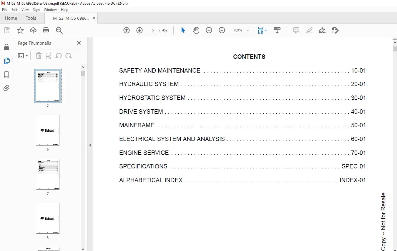
TABLE OF CONTENTS:
Bobcat MT52 & MT55 Mini Track Loader Service Manual 6986859 (10-20) – PDF DOWNLOAD
MAINTENANCE SAFETY 3
CONTENTS 5
FOREWORD 7
FOREWORD 9
SAFETY INSTRUCTIONS 11
FIRE PREVENTION 13
Maintenance 13
Operation 13
Electrical 13
Hydraulic System 13
Fueling 13
Starting 13
Spark Arrester Exhaust System 13
Welding And Grinding 14
Fire Extinguishers 14
SERIAL NUMBER LOCATION 15
Loader Serial Number 15
Engine Serial Number 15
DELIVERY REPORT 16
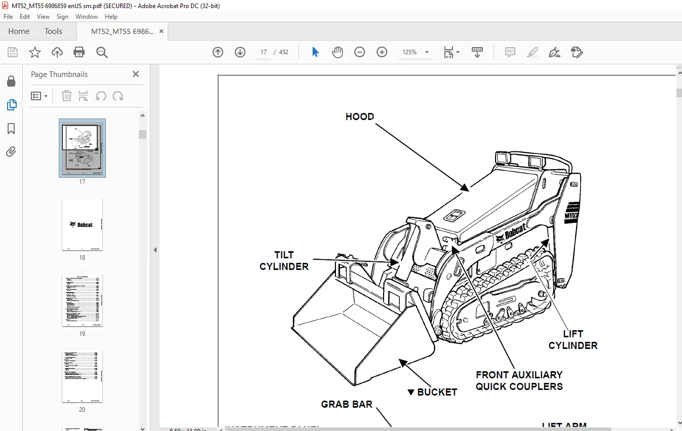
MINI LOADER IDENTIFICATION 17
SAFETY AND MAINTENANCE 19
LIFTING AND BLOCKING THE MINI LOADER 21
Procedure 21
Four Point Lift 22
LIFT ARM SUPPORT 23
Installing 23
Removing 23
TRANSPORTING THE MINI LOADER ON A TRAILER 25
Loading And Unloading 25
Fastening 25
TOWING THE MINI LOADER 27
Procedure 27
SERVICE SCHEDULE 29
Maintenance Intervals 29
AIR CLEANER SERVICE 31
Replacing Filter Elements 31
ENGINE COOLING SYSTEM 33
Cleaning 33
Checking Level 34
Removing And Replacing Coolant 35
FUEL SYSTEM 37
Fuel Specifications 37
Biodiesel Blend Fuel 37
Filling The Fuel Tank 38
Fuel Filter 39
Removing Air From The Fuel System 39
ENGINE LUBRICATION SYSTEM 41
Checking And Adding Engine Oil 41
Engine Oil Chart 41
Removing And Replacing Oil And Filter 42
HYDRAULIC / HYDROSTATIC SYSTEM 45
Checking And Adding Fluid 45
Hydraulic / Hydrostatic Fluid Chart 45
Removing And Replacing Hydraulic / Hydrostatic Filter 46
Removing And Replacing Hydraulic Fluid 46
Hydraulic Reservoir Breather 47
BOB-TACH 49
Inspection And Maintenance 49
LUBRICATING THE MINI LOADER 51
Lubrication Locations 51
Parking Brake Lubrication 53
Track Roller And Idler Lubrication 53
SPARK ARRESTER MUFFLER 55
Cleaning Procedure 55
PIVOT PINS 57
Inspection And Maintenance 57
REVERSE STOP PANEL 59
Inspection 59
LIFT AND TILT FUNCTION LOCKOUTS 61
Inspection 61
LIFT ARM BYPASS CONTROL 63
Operation 63
Inspection 63
NEUTRAL START INTERLOCKS 65
Inspecting Traction Drive Interlock 65
Inspecting The Continuous Flow Shutoff Lever 65
Inspecting Auxiliary Hydraulic Interlock 66
AUXILIARY HYDRAULIC CONTROL SYSTEM 67
Inspecting The Continuous Flow Shutoff Lever 67
Inspecting The Auxiliary Hydraulic Mode Switch (If Equipped) 67
HYDRAULIC SYSTEM 69
HYDRAULIC SCHEMATICS 71
HYDRAULIC SYSTEM INFORMATION 73
Glossary Of Hydraulic / Hydrostatic Symbols 73
Troubleshooting 77
CYLINDER (LIFT) 79
Testing 79
Removal And Installation 80
Parts Identification 81
Disassembly And Assembly 82
CYLINDER (TILT) 85
Testing 85
Removal And Installation 86
Rod End Pivot Pin Bushing And Seal Removal And Installation 87
Parts Identification 88
Disassembly And Assembly 89
MAIN RELIEF VALVE 93
Description 93
Testing 93
Removal And Installation 95
PORT RELIEF VALVES 97
Testing (Lift) 97
Removal And Installation (Lift) 99
Testing (Tilt) 100
Removal And Installation (Tilt) 102
HYDRAULIC CONTROL VALVE (S/N A3WR11001 – A3WR17614, A3WT11001 – A3WT17578, A3WU11001 – A3WU13084) 105
Description 105
Removal And Installation 105
Identification Chart 108
Disassembly And Assembly 109
HYDRAULIC CONTROL VALVE (S/N A3WR17615 & ABOVE, A3WT17579 & ABOVE, A3WU13085 & ABOVE, B38R11001 & ABOVE, B38T11001 & ABOVE, B38U11001 & ABOVE) 129
Description 129
Removal And Installation 129
Identification Chart 132
Disassembly And Assembly 133
HYDRAULIC PUMP 151
Direct Pump Testing 151
Removal And Installation 153
Parts Identification 154
Disassembly And Assembly 155
HYDRAULIC / HYDROSTATIC FILTER 157
Description 157
Housing Removal And Installation 158
HYDRAULIC FLUID RESERVOIR 159
Description 159
Removal And Installation 160
OIL COOLER 163
Description 163
Removal And Installation 163
HYDROSTATIC SYSTEM 167
HYDROSTATIC SYSTEM INFORMATION 169
Troubleshooting 169
Description 170
HYDROSTATIC MOTOR 171
Description 171
Removal And Installation 171
Parts Identification 174
Disassembly 175
Inspection 181
Assembly 183
CHARGE PRESSURE 189
Description 189
Testing 189
Sender Removal And Installation 190
Replacing Poppet Assembly 190
HYDROSTATIC PUMP 191
Description 191
Removal And Installation 191
Replenishing / High Pressure Relief Valve Removal And Installation 193
Parts Identification 194
Disassembly 195
Assembly 201
DRIVE BELT 207
Description 207
Shield Removal And Installation 207
Adjusting 208
Alignment 209
Belt Removal And Installation 209
Tensioner Pulley Removal And Installation 210
HYDROSTATIC CONTROLS 211
Steering Control Panel Removal And Installation 211
Steering Control Panel Disassembly And Assembly 213
Steering Shaft Assembly Removal And Installation 217
Steering Linkage Adjustment 219
Adjusting Reverse Speed Control 223
DRIVE SYSTEM 225
PARKING BRAKE 227
Description 227
Handle Removal And Installation 227
Cable Removal And Installation 228
Cable Adjustment 229
Linkage Assembly Removal And Assembly 230
Brake Pin Lubrication 231
TRACK CARRIAGE COMPONENTS 233
Description 233
Checking Tension 233
Adjusting Tension 234
Track Removal And Installation 235
Idler (Front) Removal And Installation 236
Idler (Front) Disassembly And Assembly 236
Idler (Rear) Removal And Installation 237
Idler (Rear) Parts Identification 238
Idler (Rear) Disassembly And Assembly 239
Tensioner Disassembly And Assembly 240
Roller Removal And Installation 240
Roller Parts Identification 241
Roller Disassembly And Assembly 242
Carriage Removal And Installation 243
Track Damage Identification 244
MAINFRAME 255
BOB-TACH 257
Removal And Installation 257
Seal Removal And Installation 258
Lever And Wedge Disassembly And Assembly 259
COMMON INDUSTRY INTERFACE (CII) 261
CII – Removal And Installation 261
CII – Seal Removal And Installation 262
CII – Lever And Wedge Disassembly And Assembly 263
LIFT ARMS 265
Removal And Installation 265
REAR DOOR 267
Removal And Installation 267
Rear Door Panel Removal And Installation 267
Striker Removal And Installation 268
Striker (Adjusting) 268
Latch Removal And Installation 269
Bumper (Adjusting) 269
FUEL TANK 271
Removal And Installation 271
Fuel Level Sender Removal And Installation 273
INSTRUMENT PANEL 275
Removal And Installation 275
GRAB BAR 277
Removal And Installation 277
HOOD 279
Removal And Installation 279
Disassembly And Assembly 280
Latch Removal And Installation 281
Striker (Adjusting) 281
REVERSE STOP PANEL 283
Description 283
Inspecting Function 283
Removal And Installation 284
Reverse Stop Mechanism Removal And Installation 284
Reverse Stop Mechanism Disassembly And Assembly 285
BOTTOM ACCESS PANEL 287
Removal And Installation 287
RIDE-ON PLATFORM (HINGED) 289
Removal And Installation 289
Tire Removal And Installation 289
Caster With Bushing Removal And Installation 290
Caster With Bearings Removal And Installation 291
Caster With Bearings Disassembly And Assembly 292
ELECTRICAL SYSTEM AND ANALYSIS 295
ELECTRICAL SCHEMATICS 297
ELECTRICAL SYSTEM INFORMATION 305
Glossary Of Electrical Symbols 305
Description 308
Fuse And Relay Location / Identification (Earlier Models) 308
Fuse And Relay Location / Identification (Later Models) 309
Troubleshooting 310
Solenoid Testing 311
BATTERY 313
Battery Maintenance 313
Maintaining Battery Charge Level 313
Battery Service During Machine Storage 313
Battery Testing 314
Battery Charging 314
Removal And Installation 315
Using A Booster Battery (Jump Starting) 316
ALTERNATOR 317
Belt Adjustment 317
Belt Replacement 317
Description 318
Alternator Output Test 319
Full Field Test 319
Alternator Voltage Testing 320
Removal And Installation 321
Parts Identification 322
STARTER 323
Testing 323
Removal And Installation 324
Parts Identification 326
INSTRUMENT PANEL 327
Component Removal And Installation 327
LIGHTS 329
Removal And Installation 329
NEUTRAL START SENSOR 331
Description 331
Removal And Installation 331
Sensor Activation Adjustment 332
Sensor Activation Bolt Removal 332
CONTINUOUS FLOW SHUTOFF SWITCH 333
Removal And Installation 333
Testing 333
ELECTRICAL / HYDRAULIC CONTROLS 335
Identification Chart 335
ELECTRIC COOLING FAN 337
Description 337
Removal And Installation 337
ENGINE SERVICE 339
ENGINE INFORMATION 341
Description 341
Specifications (Kubota D722-EB) 342
Specifications (Kubota D902-EB) 346
Torque Values 350
Troubleshooting 351
Engine Removal And Installation 353
Engine Mount Replacement 357
Compression – Checking 358
ENGINE SPEED CONTROL 359
Removal And Installation 359
Disassembly And Assembly 360
Cable Removal And Installation 360
MUFFLER 363
Removal And Installation 363
AIR CLEANER 365
Housing Removal And Installation 365
ENGINE COOLING SYSTEM 367
Radiator Removal And Installation 367
Fan Blade Removal And Installation 370
Water Pump Removal And Installation 370
Water Pump Disassembly And Assembly 371
Thermostat Housing Removal And Installation 371
LUBRICATION SYSTEM 373
Oil Pan Removal And Installation 373
Oil Pump Removal And Installation 374
Oil Pump Inspection 374
Engine Oil Pressure – Testing 375
FUEL SYSTEM 377
Fuel Camshaft Removal And Installation 377
Fuel Camshaft Governor Disassembly And Assembly 377
Fuel Shutoff Solenoid – Checking 378
Fuel Shutoff Solenoid – Installation 378
Fuel Injection Pump Removal And Installation 380
Fuel Injection Pump – Timing 382
Fuel Injector Removal And Installation 384
Fuel Injector Nozzle Pressure – Checking 385
Nozzle Spray Condition 386
Valve Seat Tightness 387
CYLINDER HEAD 389
Glow Plugs – Testing 389
Glow Plugs Removal And Installation 389
Valve Clearance Adjustment 390
Valve Timing – Checking 391
Cylinder Head Removal And Installation 392
Cylinder Head Disassembly And Assembly 394
Cylinder Head – Servicing 394
Cylinder Head Top Clearance 395
Valve Guide – Checking 395
Reconditioning The Valve And Valve Seat 397
Valve Spring 398
Valve Tappets 399
Rocker Arm And Shaft – Checking 399
CRANKSHAFT AND PISTONS 401
Piston And Connecting Rod Removal And Installation 401
Piston And Connecting Rod – Servicing 404
Cylinder Bore – Checking 406
Connecting Rod Alignment 407
Crankshaft Gear Removal And Installation 407
Crankshaft And Bearings Removal And Installation 408
Crankshaft And Bearings – Servicing 411
CAMSHAFT AND TIMING GEARS 413
Timing Gearcase Cover Removal And Installation 413
Timing Gears Backlash – Checking 415
Idler Gear And Shaft Removal And Installation 415
Camshaft – Servicing 416
Idler Gear And Shaft Servicing 418
HYDRAULIC GEAR PUMP MOUNTING BRACKET 419
Removal And Installation 419
Hydraulic Gear Pump Coupler Removal And Installation 420
FLYWHEEL AND ENGINE MOUNTING BRACKET 421
Flywheel Removal And Installation 421
Ring Gear Removal And Installation 421
Engine Mounting Bracket Removal And Installation 422
SPECIFICATIONS 423
(MT52) MINI LOADER SPECIFICATIONS 425
Machine Dimensions 425
Performance 426
Controls 426
Engine 426
Hydraulic System 427
Electrical 427
Drive System 427
Capacities 427
Tracks 428
Ground Pressure 428
(MT55) MINI LOADER SPECIFICATIONS 429
Machine Dimensions 429
Performance 430
Controls 430
Engine 430
Hydraulic System 431
Electrical 431
Drive System 431
Capacities 431
Tracks 432
Ground Pressure 432
(MT52) TECHNICAL SERVICE GUIDE SPECIFICATIONS – (S/N A3WR11001 & ABOVE, S/N A3WS11001 & ABOVE, S/N B38R11001 & ABOVE) 433
Engine 433
Engine Torques 433
Cooling System 433
Electrical 433
Loader Torques 434
Hydraulic System 434
Fuel Consumption 434
(MT55) TECHNICAL SERVICE GUIDE SPECIFICATIONS – (S/N A3WT11001 & ABOVE, S/N A3WU11001 & ABOVE, S/N B38T11001 & ABOVE, S/N B38U11001 & ABOVE) 435
Engine 435
Engine Torques 435
Cooling System 435
Electrical 435
Loader Torques 436
Hydraulic System 436
Fuel Consumption 436
TORQUE SPECIFICATIONS FOR BOLTS 437
Torque For General SAE Bolts 437
Torque For General Metric Bolts 438
HYDRAULIC CONNECTION SPECIFICATIONS 439
O-ring Face Seal Connection 439
Straight Thread O-ring Fitting 440
Tubelines And Hoses 440
Flare Fitting 440
Port Seal Fitting 441
HYDRAULIC FLUID SPECIFICATIONS 443
Specifications 443
CONVERSIONS 445
Decimal And Millimeter Equivalent Chart 445
U S To Metric Conversion Chart 445
SERVICE TOOLS REQUIRED 447
Hydraulic Tools 447
Engine Tools 448
ALPHABETICAL INDEX 449
Contact us: [email protected]
PLEASE NOTE:
- This is the SAME MANUAL used by the dealerships to diagnose your vehicle
- No waiting for couriers / posts as this is a PDF manual and you can download it within 2 minutes time once you make the payment.
- Your payment is all safe and the delivery of the manual is INSTANT – You will be taken to the DOWNLOAD PAGE.
- So have no hesitations whatsoever and write to us about any queries you may have : heydownloadss @gmail.com
S.V