Bobcat MT85 Mini Track Loader Service Manual SN B3TR11001 & Above – PDF DOWNLOAD
$29.95
Bobcat MT85 Mini Track Loader Service Manual SN B3TR11001 & Above – PDF DOWNLOAD
Description
Bobcat MT85 Mini Track Loader Service Manual SN B3TR11001 & Above – PDF DOWNLOAD
FILE DETAILS:
Bobcat MT85 Mini Track Loader Service Manual SN B3TR11001 & Above – PDF DOWNLOAD
Language : English
Pages : 405
Downloadable : Yes
File Type : PDF
IMAGES PREVIEW OF THE MANUAL:
DESCRIPTION:
Bobcat MT85 Mini Track Loader Service Manual SN B3TR11001 & Above – PDF DOWNLOAD
FOREWORD:
This manual is for the Bobcat mini track loader mechanic. It provides necessary servicing and adjustment procedures for a Bobcat mini track loader and its component parts and systems. Refer to the Operation & Maintenance manual for operating instructions, starting procedure, daily checks, etc.
SAFETY INSTRUCTIONS:
The following publications provide information on the safe use and maintenance of the Bobcat machine and attachments:
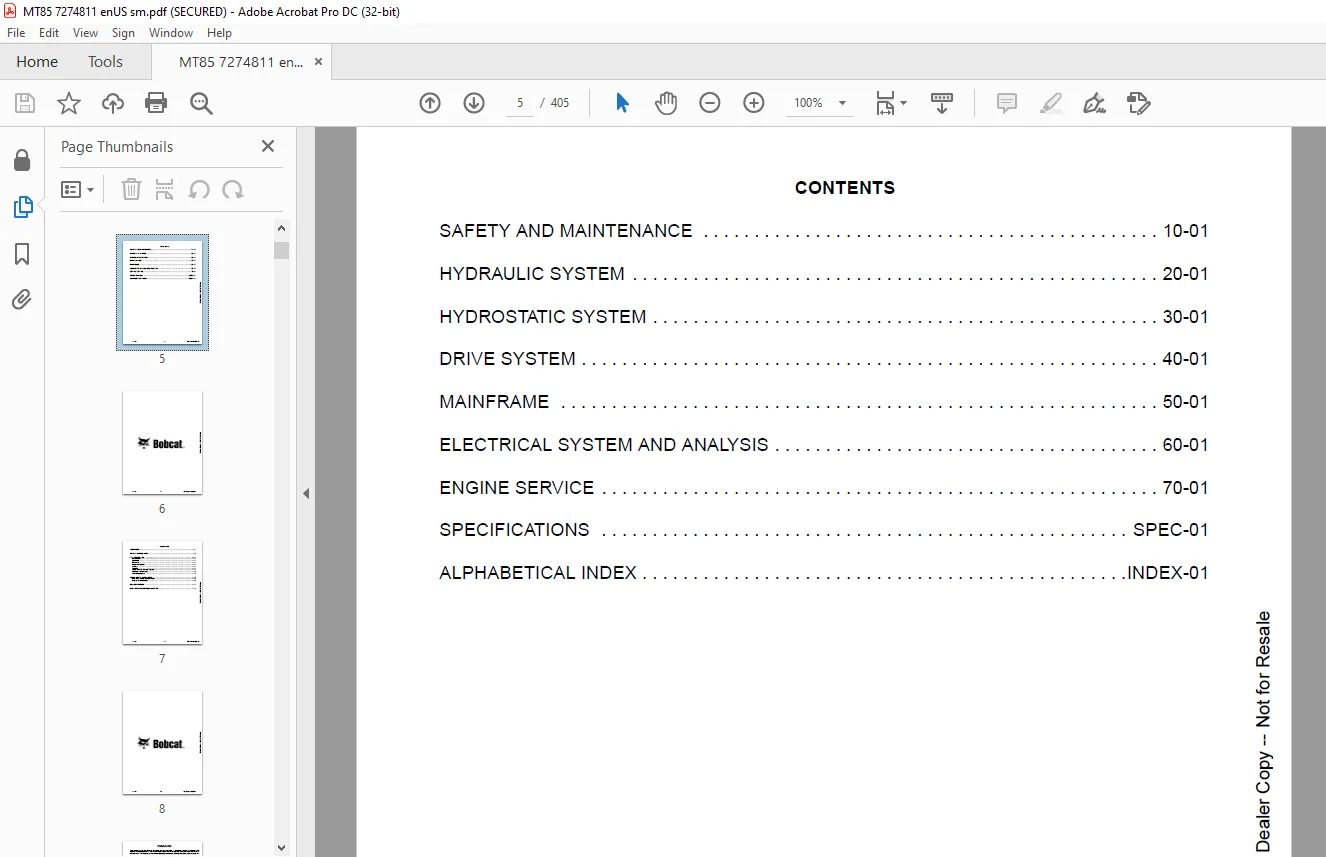
TABLE OF CONTENTS:
Bobcat MT85 Mini Track Loader Service Manual SN B3TR11001 & Above – PDF DOWNLOAD
MAINTENANCE SAFETY 3
CONTENTS 5
FOREWORD 7
FOREWORD 9
SAFETY INSTRUCTIONS 11
FIRE PREVENTION 13
Maintenance 13
Operation 13
Electrical 13
Hydraulic System 13
Fueling 13
Starting 13
Spark Arrester Exhaust System 13
Welding And Grinding 14
Fire Extinguishers 14
SERIAL NUMBER LOCATIONS 15
Mini Track Loader Serial Number 15
Engine Serial Number 15
DELIVERY REPORT 16
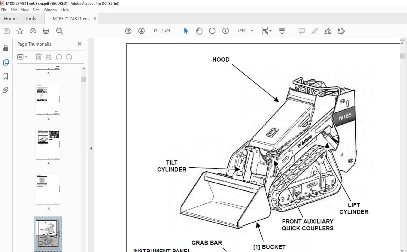
MINI TRACK LOADER IDENTIFICATION 17
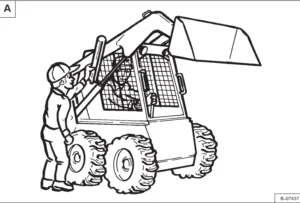
SAFETY AND MAINTENANCE 19
LIFTING AND BLOCKING THE MINI LOADER 21
Procedure 21
Four Point Lift 22
LIFT ARM SUPPORT 23
Installing 23
Removing 24
TRANSPORTING THE MINI LOADER ON A TRAILER 25
Loading And Unloading 25
Fastening 25
TOWING THE MINI LOADER 27
Procedure 27
SERVICE SCHEDULE 29
Maintenance Intervals 29
AIR CLEANER SERVICE 31
Replacing Filter Elements 31
ENGINE COOLING SYSTEM 33
Cleaning 33
Checking Level 33
Removing And Replacing Coolant 34
FUEL SYSTEM 37
Fuel Specifications 37
Biodiesel Blend Fuel 37
Filling The Fuel Tank 38
Fuel Filter 39
Removing Air From The Fuel System 40
ENGINE LUBRICATION SYSTEM 41
Checking And Adding Engine Oil 41
Engine Oil Chart 41
Removing And Replacing Oil And Filter 42
HYDRAULIC / HYDROSTATIC SYSTEM 45
Checking And Adding Fluid 45
Hydraulic / Hydrostatic Fluid Chart 45
Removing And Replacing Hydraulic / Hydrostatic Filter 46
Removing And Replacing Hydraulic Fluid 46
Hydraulic Reservoir Breather 46
BOB-TACH 47
Inspection And Maintenance 47
COMMON INDUSTRY INTERFACE 49
Inspection And Maintenance 49
LUBRICATING THE MINI LOADER 51
Lubrication Locations 51
Parking Brake Lubrication 53
Track Roller And Idler Lubrication 53
SPARK ARRESTER MUFFLER 55
Cleaning Procedure 55
PIVOT PINS 57
Inspection And Maintenance 57
LIFT AND TILT FUNCTION LOCKOUTS 59
Inspection 59
LIFT ARM BYPASS Control 61
Operation 61
Inspection 61
NEUTRAL START INTERLOCKS 63
Inspecting Traction Drive Interlock 63
Inspecting Auxiliary Hydraulic Interlock 63
AUXILIARY HYDRAULIC CONTROL SYSTEM 65
Inspecting The Continuous Flow Shutoff Pedal 65
HYDRAULIC SYSTEM 67
HYDRAULIC SYSTEM INFORMATION 71
Glossary Of Hydraulic / Hydrostatic Symbols 71
Troubleshooting 75
CYLINDER (LIFT) 77
Testing 77
Removal And Installation 78
Parts Identification 79
Disassembly And Assembly 80
CYLINDER (TILT) 83
Testing 83
Removal And Installation 84
Rod End Pivot Pin Bushing And Seal Removal And Installation 85
Parts Identification 86
Disassembly And Assembly 87
MAIN RELIEF VALVE 91
Description 91
Testing 91
Removal And Installation 93
PORT RELIEF VALVES 95
Testing (Lift) 95
Removal And Installation (Lift) 97
Testing (Tilt) 98
Removal And Installation (Tilt) 100
HYDRAULIC CONTROL VALVE 103
Description 103
Removal And Installation 103
Identification Chart 106
Disassembly And Assembly 107
HYDRAULIC PUMP 125
Direct Pump Testing 125
Removal And Installation 127
Parts Identification 128
Disassembly And Assembly 129
HYDRAULIC / HYDROSTATIC FILTER 131
Description 131
Housing Removal And Installation 131
HYDRAULIC FLUID RESERVOIR 133
Description 133
Removal And Installation 133
OIL COOLER 135
Description 135
Removal And Installation 135
HYDROSTATIC SYSTEM 137
HYDROSTATIC SYSTEM INFORMATION 139
Troubleshooting 139
Description 140
HYDROSTATIC MOTOR 141
Description 141
Removal And Installation 141
Parts Identification 144
Disassembly 145
Inspection 151
Assembly 153
CHARGE PRESSURE 159
Description 159
Testing 159
Sender Removal And Installation 160
Replacing Poppet Assembly 160
HYDROSTATIC PUMP 161
Description 161
Removal And Installation 161
Replenishing / High Pressure Relief Valve Removal And Installation 163
Parts Identification 164
Disassembly 165
Assembly 171
DRIVE BELT 177
Description 177
Shield Removal And Installation 177
Adjusting 178
Alignment 179
Belt Removal And Installation 179
Tensioner Pulley Removal And Installation 180
HYDROSTATIC CONTROLS 181
Pump Controls Disassembly And Assembly (Earlier Models) 181
Pump Controls Disassembly And Assembly (Later Models) 182
Pump Controls Disassembly And Assembly (All Models) 183
Pump Controls Adjustment 185
Travel Control Lever Adjustment (Earlier Models) 187
Travel Control Lever Adjustment (Later Models) 187
Full Forward Travel Adjustment 188
Steering Drift Adjustment 189
DRIVE SYSTEM 191
PARKING BRAKE (EARLIER MODELS) 193
Description 193
Handle Removal And Installation 193
Cable Removal And Installation 194
Cable Adjustment 195
Linkage Assembly Removal And Assembly 196
Brake Pin Lubrication 197
PARKING BRAKE (LATER MODELS) 199
Description 199
Handle Removal And Installation 199
Cable Removal And Installation 200
Cable Adjustment 201
Linkage Assembly Removal And Assembly 202
Brake Pin Lubrication 203
TRACK CARRIAGE COMPONENTS 205
Description 205
Checking Tension 205
Adjusting Tension 206
Track Removal And Installation 207
Idler (Front) Removal And Installation 209
Idler (Front) Disassembly And Assembly 209
Idler (Rear) Removal And Installation 210
Idler (Rear) Parts Identification 211
Idler (Rear) Disassembly And Assembly 212
Tensioner Disassembly And Assembly 213
Roller Removal And Installation 213
Roller Parts Identification 214
Roller Disassembly And Assembly 215
Carriage Removal And Installation 216
Track Damage Identification 217
MAINFRAME 227
BOB-TACH 229
Removal And Installation 229
Seal Removal And Installation 230
Lever And Wedge Disassembly And Assembly 231
COMMON INDUSTRY INTERFACE (CII) 233
CII – Removal And Installation 233
CII – Seal Removal And Installation 234
CII – Lever And Wedge Disassembly And Assembly 235
LIFT ARMS 237
Removal And Installation 237
REAR DOOR 239
Removal And Installation 239
Latch Removal And Installation 240
Bumper (Adjusting) 240
FUEL TANK 241
Removal And Installation 241
Fuel Level Sender Removal And Installation 243
INSTRUMENT PANEL 245
Removal And Installation 245
GRAB BAR 247
Removal And Installation 247
HOOD 249
Removal And Installation 249
Disassembly And Assembly 250
Latch Removal And Installation 251
Striker (Adjusting) 251
BOTTOM ACCESS PANEL 253
Removal And Installation 253
OPERATOR PLATFORM 255
Removal And Installation 255
Operator Cushion Removal And Installation 256
Continuous Flow Shutoff System Pedal Removal And Installation 256
ELECTRICAL SYSTEM AND ANALYSIS 257
ELECTRICAL SCHEMATICS 259
ELECTRICAL SYSTEM INFORMATION 268
Glossary Of Electrical Symbols 268
Description 271
Fuse And Relay Location / Identification 271
Troubleshooting 272
Solenoid Testing 273
BATTERY 274
Battery Maintenance 274
Maintaining Battery Charge Level 274
Battery Service During Machine Storage 274
Battery Testing 275
Battery Charging 275
Removal And Installation 276
Using A Booster Battery (Jump Starting) 277
ALTERNATOR 278
Belt Adjustment 278
Belt Replacement 278
Description 279
Alternator Output Test 280
Full Field Test 280
Alternator Voltage Testing 281
Removal And Installation 282
Parts Identification 283
STARTER 284
Testing 284
Removal And Installation 285
Parts Identification 287
INSTRUMENT PANEL 288
Component Removal And Installation 288
NEUTRAL START SENSOR 290
Description 290
Removal And Installation 290
CONTINOUS FLOW SHUTOFF SYSTEM SENSOR 292
Description 292
Removal And Installation 293
Adjustment 294
Testing 294
ELECTRICAL / HYDRAULIC CONTROLS 296
Identification Chart 296
ELECTRIC COOLING FAN 298
Description 298
Removal And Installation 298
ENGINE SERVICE 300
ENGINE INFORMATION 302
Description 302
Specifications (Kubota D902-EB) 303
Torque Values 307
Troubleshooting 308
Engine Removal And Installation 310
Engine Mount Replacement 314
Compression – Checking 315
ENGINE SPEED CONTROL 316
Removal And Installation 316
Disassembly And Assembly 317
Cable Removal And Installation 317
MUFFLER 320
Removal And Installation 320
AIR CLEANER 322
Housing Removal And Installation 322
ENGINE COOLING SYSTEM 324
Radiator Removal And Installation 324
Fan Blade Removal And Installation 327
Water Pump Removal And Installation 327
Water Pump Disassembly And Assembly 328
Thermostat Housing Removal And Installation 328
LUBRICATION SYSTEM 330
Oil Pan Removal And Installation 330
Oil Pump Removal And Installation 331
Oil Pump Inspection 331
Engine Oil Pressure – Testing 332
FUEL SYSTEM 334
Fuel Camshaft Removal And Installation 334
Fuel Camshaft Governor Disassembly And Assembly 334
Fuel Shutoff Solenoid – Checking 335
Fuel Shutoff Solenoid – Installation 335
Fuel Injection Pump Removal And Installation 337
Fuel Injection Pump – Timing 339
Fuel Injector Removal And Installation 341
Fuel Injector Nozzle Pressure – Checking 342
Nozzle Spray Condition 343
Valve Seat Tightness 344
CYLINDER HEAD 346
Glow Plugs – Testing 346
Glow Plugs Removal And Installation 346
Valve Clearance Adjustment 347
Valve Timing – Checking 348
Cylinder Head Removal And Installation 349
Cylinder Head Disassembly And Assembly 351
Cylinder Head – Servicing 351
Cylinder Head Top Clearance 352
Valve Guide – Checking 352
Reconditioning The Valve And Valve Seat 354
Valve Spring 355
Valve Tappets 356
Rocker Arm And Shaft – Checking 356
CRANKSHAFT AND PISTONS 358
Piston And Connecting Rod Removal And Installation 358
Piston And Connecting Rod – Servicing 361
Cylinder Bore – Checking 363
Connecting Rod Alignment 364
Crankshaft Gear Removal And Installation 364
Crankshaft And Bearings Removal And Installation 365
Crankshaft And Bearings – Servicing 368
CAMSHAFT AND TIMING GEARS 370
Timing Gearcase Cover Removal And Installation 370
Timing Gears Backlash – Checking 372
Idler Gear And Shaft Removal And Installation 372
Camshaft – Servicing 373
Idler Gear And Shaft Servicing 375
HYDRAULIC GEAR PUMP MOUNTING BRACKET 376
Removal And Installation 376
Hydraulic Gear Pump Coupler Removal And Installation 377
FLYWHEEL AND ENGINE MOUNTING BRACKET 378
Flywheel Removal And Installation 378
Ring Gear Removal And Installation 378
Engine Mounting Bracket Removal And Installation 379
SPECIFICATIONS 380
(MT85) MINI TRACK LOADER SPECIFICATIONS 382
Dimensions (Narrow Track) 382
Dimensions (Wide Track) 383
Performance 384
Controls 384
Engine 384
Hydraulic System 385
Electrical 385
Drive System 385
Capacities 385
Tracks 386
Ground Pressure 386
(MT85) TECHNICAL SERVICE GUIDE SPECIFICATIONS 388
Engine 388
Engine Torques 388
Cooling System 388
Electrical 388
Loader Torques 389
Hydraulic System 389
Fuel Consumption 389
TORQUE SPECIFICATIONS FOR BOLTS 390
Torque For General SAE Bolts 390
Torque For General Metric Bolts 391
HYDRAULIC CONNECTION SPECIFICATIONS 392
O-ring Face Seal Connection 392
Straight Thread O-ring Fitting 393
Tubelines And Hoses 393
Flare Fitting 394
Port Seal Fitting 394
HYDRAULIC FLUID SPECIFICATIONS 396
Specifications 396
CONVERSIONS 398
Decimal And Millimeter Equivalent Chart 398
U S To Metric Conversion Chart 398
SERVICE TOOLS REQUIRED 400
Hydraulic Tools 400
Engine Tools 401
ALPHABETICAL INDEX 402
Questions? Email us: [email protected]
PLEASE NOTE:
- This is not a physical manual but a digital manual – meaning no physical copy will be couriered to you. The manual can be yours in the next 2 mins as once you make the payment, you will be directed to the download page IMMEDIATELY.
- This is the same manual used by the dealers inorder to diagnose your vehicle of its faults.
- Require some other service manual or have any queries: please WRITE to us at [email protected]
S.V