Bobcat S100 Skid-Steer Loader Service Manual 6904926 (01-09) – PDF DOWNLOAD
$30.95
Description
Bobcat S100 Skid-Steer Loader Service Manual 6904926 (01-09) – PDF DOWNLOAD
FILE DETAILS:
Bobcat S100 Skid-Steer Loader Service Manual 6904926 (01-09) – PDF DOWNLOAD
Language : English
Pages : 521
Downloadable : Yes
File Type : PDF
DESCRIPTION:
Bobcat S100 Skid-Steer Loader Service Manual 6904926 (01-09) – PDF DOWNLOAD
S/N A2G811001 & Above
S/N A8ET11001 – A8ET19999
FOREWORD:
This manual is for the Bobcat loader mechanic. It provides necessary servicing and adjustment procedures for the Bobcat loader and its component parts and systems. Refer to the Operation & Maintenance Manual for operating instructions, starting procedure, daily checks, etc.
A general inspection of the following items must be made after the loader has had service or repair:
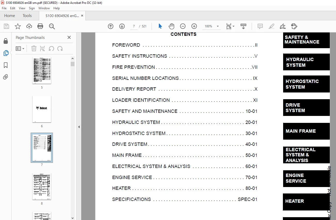
TABLE OF CONTENTS:
Bobcat S100 Skid-Steer Loader Service Manual 6904926 (01-09) – PDF DOWNLOAD
MAINTENANCE SAFETY 3
ALPHABETICAL INDEX 5
CONTENTS 7
FOREWORD 8
SAFETY INSTRUCTIONS 11
FIRE PREVENTION 13
Maintenance 13
Operation 13
Electrical 13
Hydraulic System 13
Fueling 13
Starting 13
Spark Arrestor Exhaust System 13
Welding And Grinding 14
Fire Extinguishers 14
SERIAL NUMBER LOCATIONS 15
Loader Serial Number 15
Engine Serial Number 15
DELIVERY REPORT 16
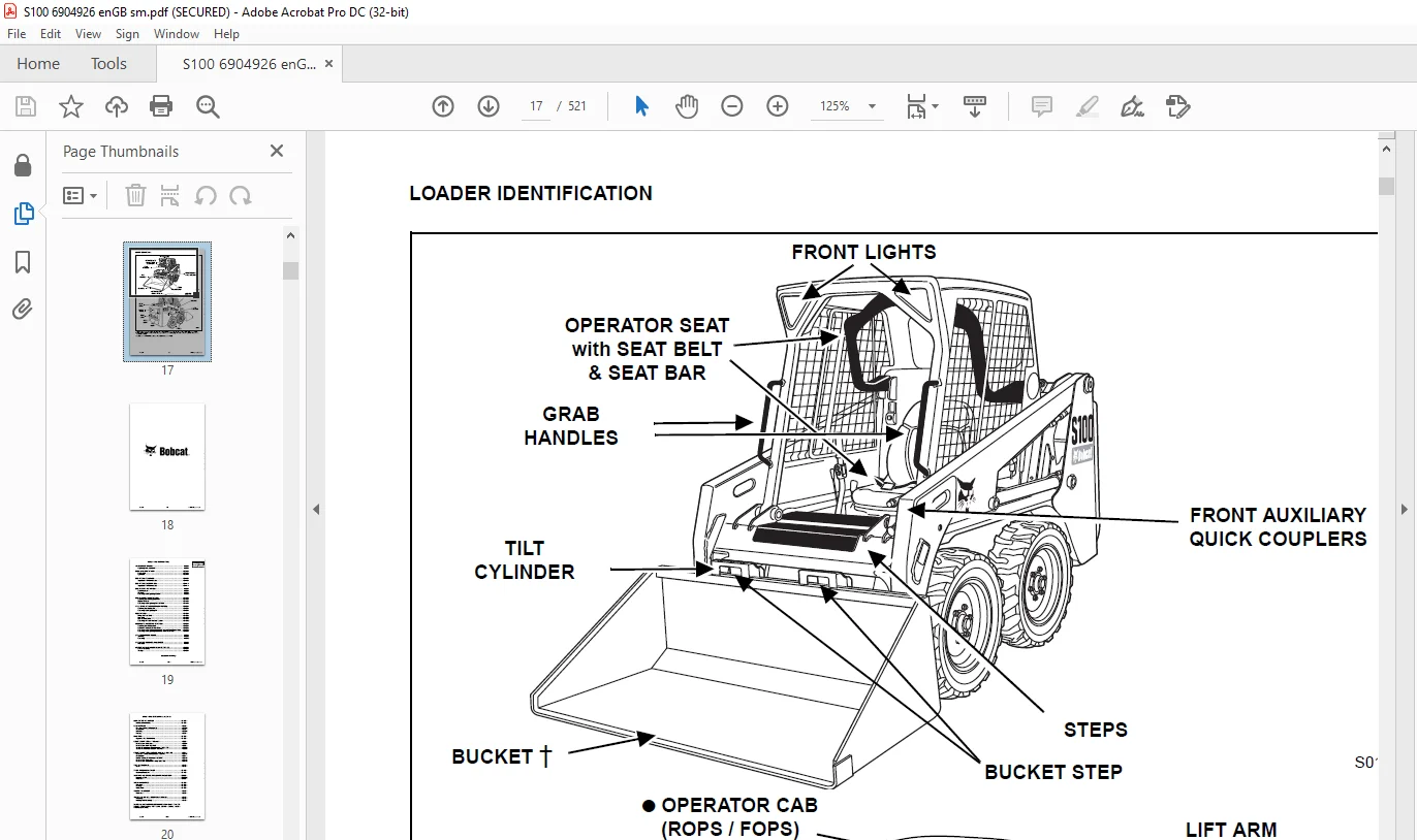
LOADER IDENTIFICATION 17
SAFETY AND MAINTENANCE 19
LIFTING AND BLOCKING THE LOADER 21
Procedure 21
LIFT ARM SUPPORT DEVICE 23
Installing 23
Removing 24
OPERATOR CAB 25
Description 25
Raising 25
Lowering 26
Cab Door Sensor (If Equipped) 27
TRANSPORTING THE LOADER ON A TRAILER 29
Loading And Unloading 29
Fastening 29
TOWING THE LOADER 31
Procedure 31
REMOTE START TOOL KIT-MEL1563 33
Remote Start Tool – MEL1563 33
Service Tool Harness Control – MEL1565 34
Service Tool Harness Communicator – MEL1566 35
Remote Start Procedure 36
REMOTE START TOOL (SERVICE TOOL) KIT – 6689779 39
Description 39
Remote Start Tool (Service Tool) – 6689778 40
Loader Service Tool Harness – 6689747 41
Computer Service Tool Harness – 6689746 42
Remote Start Procedure 43
SERVICE SCHEDULE 47
Chart 47
AIR CLEANER SERVICE 49
Replacing Filter Elements 49
ENGINE COOLING SYSTEM 51
Cleaning 51
Checking Level 51
Removing And Replacing Coolant 52
FUEL SYSTEM 53
Fuel Specifications 53
Filling The Fuel Tank 53
Fuel Filter 54
Removing Air From The Fuel System 54
ENGINE LUBRICATION SYSTEM 55
Checking And Adding Engine Oil 55
Engine Oil Chart 55
Removing And Replacing Oil And Filter 55
HYDRAULIC / HYDROSTATIC SYSTEM 57
Checking And Adding Fluid 57
Hydraulic / Hydrostatic Fluid Chart 57
Removing And Replacing Hydraulic / Hydrostatic Filter 57
Removing And Replacing Hydraulic Fluid and Case Drain Filters 58
Removing And Replacing Charge Filter 59
FINAL DRIVE TRANSMISSION (CHAINCASE) 61
Checking And Adding Oil 61
Removing And Replacing Oil 61
BOB-TACH (HAND LEVER) 63
Inspection And Maintenance 63
BOB-TACH (POWER OPTION) 65
Inspection And Maintenance 65
LUBRICATING THE LOADER 67
Lubrication Locations 67
TIRE MAINTENANCE 69
Wheel Nuts 69
Rotating 69
Mounting 69
SPARK ARRESTOR MUFFLER 71
Cleaning Procedure 71
PIVOT PINS 73
Inspection And Maintenance 73
LOADER STORAGE AND RETURN TO SERVICE 75
Storage 75
Return To Service 75
STOPPING THE ENGINE AND LEAVING THE LOADER 77
Procedure 77
Emergency Exit 78
BACK-UP ALARM SYSTEM 79
Description 79
Operation 79
HYDRAULIC SYSTEM 81
HYDRAULIC / HYDROSTATIC SCHEMATIC 85
HYDRAULIC SYSTEM INFORMATION 87
Glossary Of Hydraulic / Hydrostatic Symbols 87
Troubleshooting 91
CYLINDER (LIFT) 93
Testing 93
Removal And Installation 94
Parts Identification 95
Disassembly And Assembly 96
CYLINDER (TILT) 99
Testing 99
Removal And Installation 99
Parts Identification 101
Disassembly And Assembly 102
CYLINDER (BOB-TACH) 105
Testing 105
Removal And Installation 106
Parts Identification 107
Disassembly and Assembly 108
MAIN RELIEF VALVE 111
Description 111
Testing 111
Adjusting 112
Removal And Installation 112
HYDRAULIC CONTROL VALVE 113
Description 113
Removal And Installation 113
Identification Chart 116
Load Check Valve Removal And Installation (Tilt and Auxiliary) 117
Anti-Cavitation Valve Removal And Installation (Lift, Rod End) 118
Port Relief / Anti-Cavitation Valve Removal And Installation (Lift, Base End) 119
Port Relief / Anti-Cavitation Valve Removal And Installation (Tilt, Base End) 119
Port Relief / Anti-Cavitation Valve Removal And Installation (Tilt, Rod End) 120
Port Relief Valve Removal And Installation 120
Rubber Boot Removal And Installation 121
End Cap / Spool Lock Block Removal And Installation 121
Lift Spool And Detent Removal And Installation 122
Tilt Spool Removal And Installation 131
Auxiliary Spool Removal And Installation 133
Solenoid Removal And Installation 141
Lock Valve Removal And Installation 142
Main Relief Valve Removal And Installation 144
LIFT ARM bypass CONTROL VALVE 145
Description 145
Testing 145
Removal and Installation 145
Disassembly And Assembly 147
HYDRAULIC PUMP 149
Description 149
Pump Test at Quick Couplers 149
Direct Pump Test 150
Direct Pump Test (Charge Section) 151
Removal And Installation 154
Parts Identification 157
Disassembly And Assembly 158
Hydraulic Pump Start Up 162
HYDRAULIC / HYDROSTATIC FILTERS 163
Description 163
Hydraulic / Hydrostatic Filter Housing Removal And Installation 163
HYDRAULIC FLUID RESERVOIR 165
Description 165
Removal And Installation 165
Hydraulic Fluid Screen 166
OIL COOLER 167
Description 167
Removal And Installation 167
BUCKET POSITION VALVE 169
Description 169
Solenoid Removal And Installation 169
Solenoid Testing 170
Removal And Installation 170
Disassembly And Assembly 173
BOB-TACH (POWER) BLOCK 175
Description 175
Removal And Installation 175
Disassembly And Assembly 177
FRONT AUXILIARY HYDRAULIC COUPLERS 181
Description 181
Removal And Installation 181
HYDROSTATIC SYSTEM 183
HYDROSTATIC SYSTEM INFORMATION 185
Description 185
Troubleshooting 186
HYDROSTATIC MOTOR 187
Description 187
Removal And Installation 187
Disassembly And Assembly 188
CHARGE PRESSURE 193
Description 193
Testing 193
Sender Removal And Installation 194
Adjusting 195
HYDROSTATIC PUMP 197
Description 197
Replenishing / High Pressure Relief Valve Removal And Installation 197
Removal And Installation 198
Parts Identification 201
Disassembly 202
Assembly 207
Hydrostatic Pump Start Up 211
DRIVE BELT 213
Description 213
Shield Removal And Installation 213
Adjusting 213
Belt Removal And Installation 214
Tensioner Pulley Removal And Installation 214
Tensioner Pulley Disassembly And Assembly 214
CASE DRAIN FILTER 215
Description 215
Disassembly And Assembly 215
DRIVE SYSTEM 217
BRAKE 219
Description 219
Disk Removal And Installation 219
DRIVE COMPONENTS 221
Description 221
Axle Seal Removal And Installation 222
Axle Sprocket And Bearings Removal And Installation 224
Chain Removal And Installation 228
CHAINCASE 231
Description 231
Front Cover Removal And Installation 231
Center Cover Removal And Installation 232
MAIN FRAME 235
SEAT BAR 239
Description 239
Removal And Installation 239
Disassembly And Assembly 241
Compression Spring Disassembly And Assembly 242
OPERATOR CAB 243
Gas Cylinder Removal And Installation 243
Gas Cylinder Bracket Disassembly And Assembly 245
Removal And Installation 246
OPERATOR SEAT 249
Removal And Installation 249
Seat Belt Removal And Installation 249
OPERATOR SEAT (SUSPENSION) 251
Removal And Installation 251
Slide Rail Removal And Installation 252
Seat Belt Removal and Installation 252
Lower Cushion Removal And Installation 253
Back Cushion Removal And Installation 253
Shock Removal And Installation 254
3-Point Seat Belt Removal And Installation 254
BOB-TACH HAND LEVER 257
Description 257
Removal And Installation 257
Lever And Wedge Disassembly And Assembly 259
Pivot Pin Bushing And Seal Removal And Installation 260
BOB-TACH (POWER OPTION) 261
Description 261
Removal And Installation 261
Lever And Wedge Disassembly And Assembly 263
Pivot Pin Bushing And Seal Removal And Installation 264
LIFT ARMS 265
Removal And Installation 265
REAR GRILL 271
Removal And Installation 271
REAR DOOR 273
Removal And Installation 273
Striker Removal and Installation 274
Striker Disassembly and Assembly 274
Striker (Adjusting) 274
Latch Removal And Installation 275
FUEL TANK 277
Removal And Installation 277
Fuel Level Sender Removal And Installation 278
Fuel Fill Screen Removal And Installation 278
Fuel Pickup Screen 279
CONTROL PEDALS AND LINKAGES 281
Description 281
Pedal Removal And Installation 281
Linkage Removal And Installation 282
Pedal (Adjusting) 282
CONTROL PANEL 283
Description 283
Removal and Installation 284
Shaft Removal And Installation 287
Shaft Disassembly And Assembly 287
Linkage Removal And Installation 288
Pintle Arm Removal And Installation 289
Pintle Arm Disassembly and Assembly 292
Linkage Neutral Adjusting 293
Linkage Travel Adjusting 296
CONTROL HANDLE / LEVER 301
Description 301
Lever Removal And Installation 301
Boot Removal And Installation 301
WINDOW (REAR) 303
Removal 303
Installation 303
WINDOW (TOP) 305
Removal And Installation 305
WINDOW (SIDE) 307
Removal And Installation 307
WINDOW (FRONT DOOR) 309
Removal (Standard Window) 309
Installation (Standard Window) 310
Removal And Installation (Special Applications Window) 311
CAB DOOR 313
Description 313
Removal And Installation 313
Aligning 314
Adjusting 315
Checking Operation 315
ELECTRICAL SYSTEM & ANALYSIS 317
ELECTRICAL SCHEMATIC 321
ELECTRICAL SYSTEM INFORMATION 322
Glossary Of Electrical Symbols 322
Cab Harness Connectors 325
Mainframe Harness Connectors 326
Description 327
Troubleshooting 328
Fuse And Relay Location / Identification 329
Solenoid Testing 330
BATTERY 332
Removal And Installation 332
Servicing 333
Using A Booster Battery (Jump Starting) 334
ALTERNATOR 336
Belt Adjustment 336
Charging System Inspection 336
Alternator Voltage Testing 337
Low Voltage Testing 338
High Voltage Testing 338
Removal And Installation 339
Parts Identification 341
STARTER 342
Testing 342
Removal And Installation 343
Parts Identification 344
INSTRUMENT PANELS 346
Left Panel 346
LCD Screen Functions 348
Standard Key Panel 348
Deluxe Instrumentation Panel 349
Option And Field Accessory Panels 350
Removal And Installation (Left And Right) 351
Key Switch Removal And Installation 352
Alarm Removal And Installation 352
Front Accessory Panel Removal And Installation 353
LIGHTS 354
Front Removal And Installation 354
Rear Removal And Installation 354
Cab Light Removal And Installation 355
BOBCAT CONTROLLER (MAIN) 356
Description 356
Connector Identification 357
Removal And Installation 359
DIAGNOSTIC SERVICE CODES 360
Viewing Service Codes (Standard Key Panel) 360
Viewing Service Codes (Deluxe Instrumentation Panel) 360
Service Codes List 361
BOBCAT INTERLOCK CONTROL SYSTEM (BICS) 366
Description 366
Inspecting The BICS Controller (Engine STOPPED – Key ON) 366
Inspecting The Seat Bar Sensor (Engine RUNNING) 366
Inspecting The Traction Lock (Engine RUNNING) 367
Inspecting The Lift Arm Bypass Control 367
Troubleshooting 368
Troubleshooting Chart 369
SEAT BAR SENSOR 370
Description 370
Troubleshooting 370
Testing 371
Removal And Installation 372
Bobcat Interlock Control System (BICS) Circuit Test 374
TRACTION LOCK 376
Description 376
Troubleshooting 376
Removal And Installation 377
Inspecting 380
SERVICE PC (LAPTOP) 382
Connecting To The Remote Start Tool 382
Connecting Remote Start Tool (Service Tool) 382
FLYWHEEL RPM SENSOR 384
Description 384
Adjusting 384
CONTROL PANEL SETUP 386
Right Panel Setup (Deluxe Instrumentation Panel) 386
Attachment Control Information (Deluxe Instrumentation Panel) 387
PASSWORD SETUP 388
Password Description 388
Changing The Owner Password 388
Changing The User Passwords 389
Password Lockout Feature 389
MAINTENANCE CLOCK 390
Description 390
Setup 391
Reset 394
BACK-UP ALARM SYSTEM 396
Description 396
Inspecting 396
Adjusting Switch Position 397
Troubleshooting 398
Alarm Removal And Installation 399
Switch Removal And Installation 399
ENGINE SERVICE 402
ENGINE INFORMATION 404
Description 404
Specifications 405
Torque Values 409
Troubleshooting 411
Engine Removal And Installation 412
Engine Mount Replacement 420
Compression-Checking 421
ENGINE SPEED CONTROL 422
Removal And Installation 422
MUFFLER 424
Removal And Installation 424
AIR CLEANER 426
Removal And Installation 426
ENGINE COOLING SYSTEM 428
Radiator Removal And Installation 428
Fan Removal And Installation 429
Water Pump Removal And Installation 429
Water Pump Disassembly And Assembly 430
Thermostat Housing Removal And Installation 430
Testing The Thermostat 431
LUBRICATION SYSTEM 432
Oil Pan Removal And Installation 432
Oil Pump Removal And Installation 432
Oil Pump Inspection 433
Oil Pump Inspection (Cont’d) 434
Engine Oil Pressure – Testing 434
FUEL SYSTEM 436
Fuel Camshaft Removal And Installation 436
Fuel Camshaft Governor Disassembly And Assembly 436
Fuel Shutoff Solenoid – Checking 437
Fuel Shutoff Solenoid Removal And Installation 438
Fuel Injection Pump Removal And Installation 439
Timing The Injection Pump 441
Fuel Injector Removal And Installation 443
Fuel Injector Nozzles Pressure – Checking 444
Nozzle Spray Condition 445
Valve Seat Tightness 446
CYLINDER HEAD 448
Glow Plug – Testing 448
Glow Plug Removal And Installation 449
Valve Clearance Adjustment 449
Valve Timing – Checking 450
Cylinder Head Removal And Installation 451
Cylinder Head Disassembly and Assembly 453
Cylinder Head – Servicing 453
Cylinder Head Top Clearance 454
Valve Guide – Checking 454
Reconditioning The Valve And Valve Seat 455
Valve Spring 457
Valve Tappets 458
Rocker Arm And Shaft – Checking 458
CRANKSHAFT AND PISTONS 460
Piston And Connecting Rod Removal And Installation 460
Piston And Connecting Rod – Servicing 462
Cylinder Bore Checking 464
Connecting Rod Alignment 464
Crankshaft And Bearings Removal And Installation 465
Crankshaft And Bearings – Servicing 466
CAMSHAFT AND TIMING GEARS 472
Timing Gearcase Cover Removal And Installation 472
Timing Gears Backlash – Checking 474
Idler Gear And Shaft Removal And Installation 474
Camshaft – Servicing 475
Idler Gear And Shaft Servicing 477
FLYWHEEL 478
Flywheel Removal And Installation 478
HEATER 480
HEATER SYSTEM 482
Description 482
REGULAR MAINTENANCE 484
Filter Elements Removal And Installation 484
Cleaning The Heater Coil 485
TROUBLESHOOTING 486
Blower Motor Does Not Operate 486
Blower Motor Operators Normally, But Air Flow Is Insufficient 486
Electrical System 487
Engine Coolant Bypassing The Heater Valve 491
Heater Valve Not Opening Or Closing 491
HEATER UNIT 494
Removal And Installation 494
HEATER COIL 496
Removal And Installation 496
HEATER FAN 498
Blower Removal And Installation 498
Disassembly And Assembly 499
Connector Identification 501
HEATER VALVE 502
Removal and Installation 502
Disassembly And Assembly 503
SPECIFICATIONS 504
LOADER SPECIFICATIONS 506
Machine Dimensions 506
Machine Rating 507
Function Time 507
Weights 507
Engine 507
Electrical 508
Hydraulic System 508
Hydraulic Cylinders 508
Drive System 508
Traction 509
Environmental 509
Fluid Capacities 509
Fluid Specifications 510
Controls 510
Instrumentation 511
TORQUE SPECIFICATIONS FOR BOLTS 512
Torque For General SAE Bolts 512
Torque For General Metric Bolts 513
HYDRAULIC CONNECTION SPECIFICATIONS 514
O-ring Face Seal Connection 514
Straight Thread O-ring Fitting 515
Tubelines And Hoses 515
Flare Fitting 515
Port Seal Fitting 516
HYDRAULIC / HYDROSTATIC FLUID SPECIFICATIONS 518
Specifications 518
CONVERSIONS 520
Decimal And Millimeter Equivalent Chart 520
U S To Metric Conversion Chart 520
IMAGES PREVIEW OF THE MANUAL:
Questions? Email us: [email protected]
PLEASE NOTE:
- This is the SAME MANUAL used by the dealerships to diagnose your vehicle
- No waiting for couriers / posts as this is a PDF manual and you can download it within 2 minutes time once you make the payment.
- Your payment is all safe and the delivery of the manual is INSTANT – You will be taken to the DOWNLOAD PAGE.
- So have no hesitations whatsoever and write to us about any queries you may have : heydownloadss @gmail.com
S.V