Bobcat S100 Skid-Steer Loader Service Manual 6904926 (10-12) – PDF DOWNLOAD
$30.95
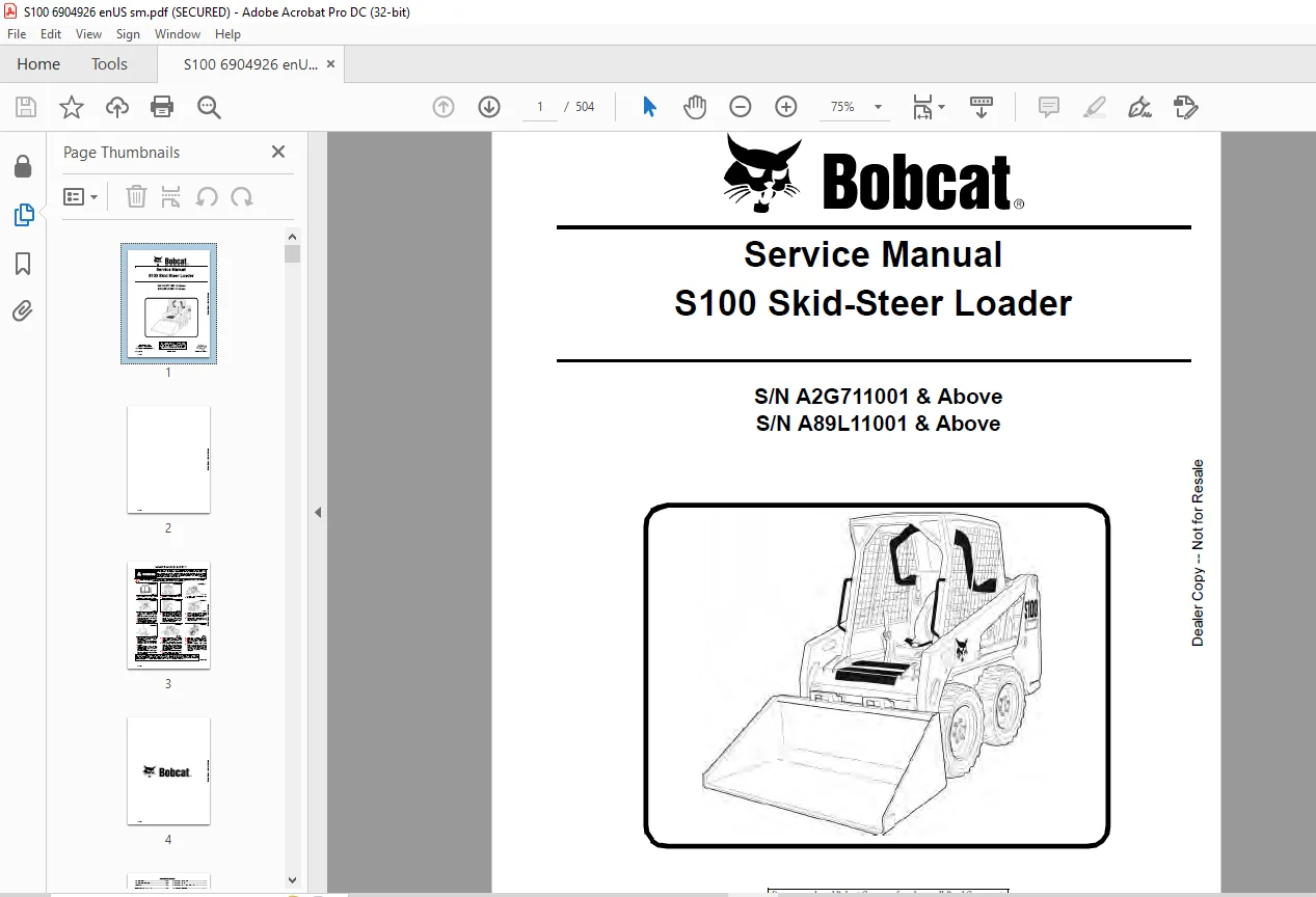
Bobcat S100 Skid-Steer Loader Service Manual 6904926 (10-12) – PDF DOWNLOAD
S/N A2G711001 & Above
S/N A89L11001 & Above
Description
Bobcat S100 Skid-Steer Loader Service Manual 6904926 (10-12) – PDF DOWNLOAD
FILE DETAILS:
Bobcat S100 Skid-Steer Loader Service Manual 6904926 (10-12) – PDF DOWNLOAD
Language : English
Pages : 504
Downloadable : Yes
File Type : PDF
DESCRIPTION:
Bobcat S100 Skid-Steer Loader Service Manual 6904926 (10-12) – PDF DOWNLOAD
S/N A2G711001 & Above
S/N A89L11001 & Above
FOREWORD:
This manual is for the Bobcat loader mechanic. It provides necessary servicing and adjustment procedures for the Bobcat loader and its component parts and systems. Refer to the Operation & Maintenance Manual for operating instructions, starting procedure, daily checks, etc.
A general inspection of the following items must be made after the loader has had service or repair:
TABLE OF CONTENTS:
Bobcat S100 Skid-Steer Loader Service Manual 6904926 (10-12) – PDF DOWNLOAD
MAINTENANCE SAFETY 3
ALPHABETICAL INDEX 5
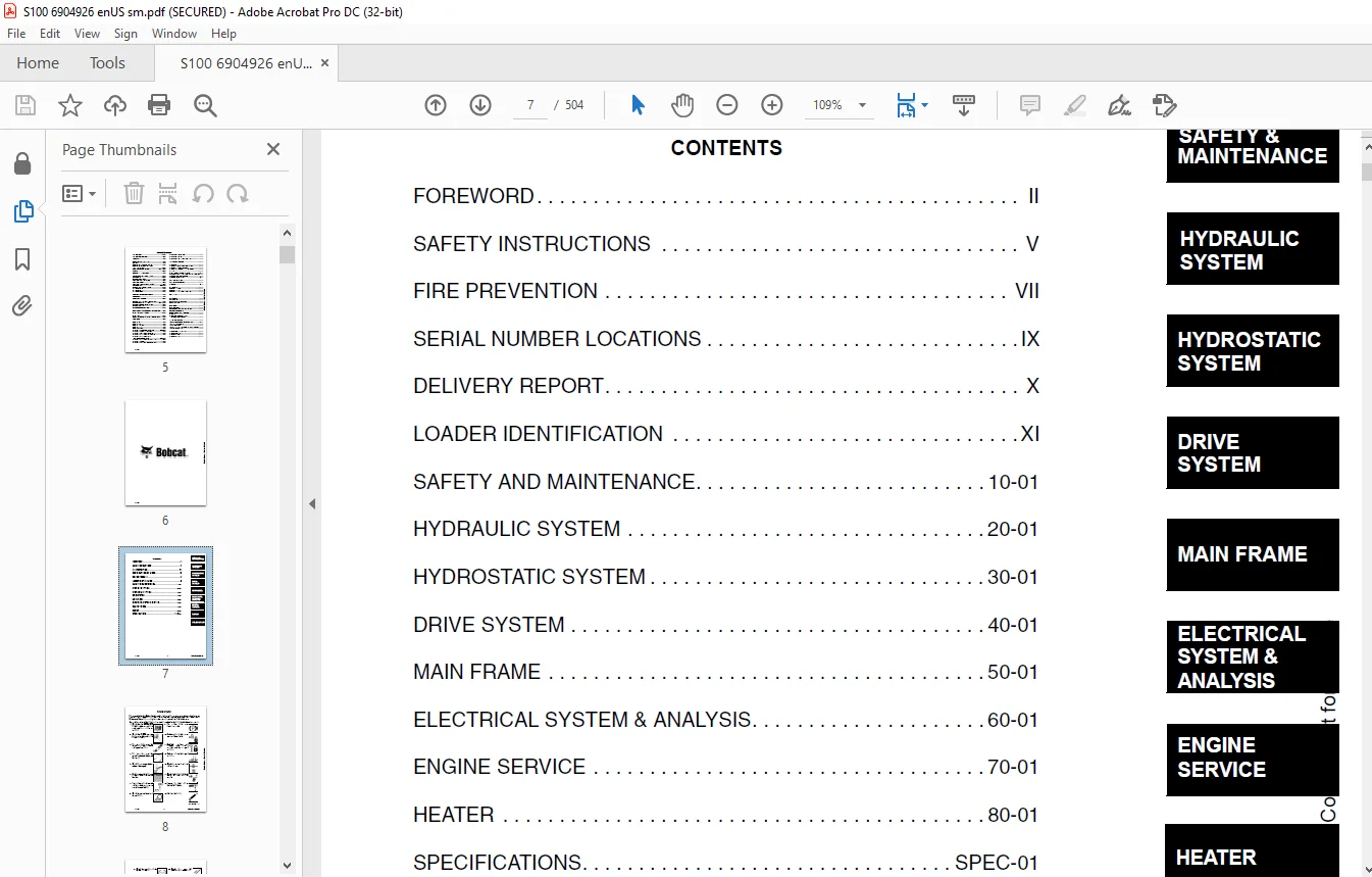
CONTENTS 7
FOREWORD 8
SAFETY INSTRUCTIONS 11
FIRE PREVENTION 13
Maintenance 13
Operation 13
Electrical 13
Hydraulic System 13
Fueling 13
Starting 13
Spark Arrestor Exhaust System 13
Welding And Grinding 14
Fire Extinguishers 14
SERIAL NUMBER LOCATIONS 15
Loader Serial Number 15
Engine Serial Number 15
DELIVERY REPORT 16
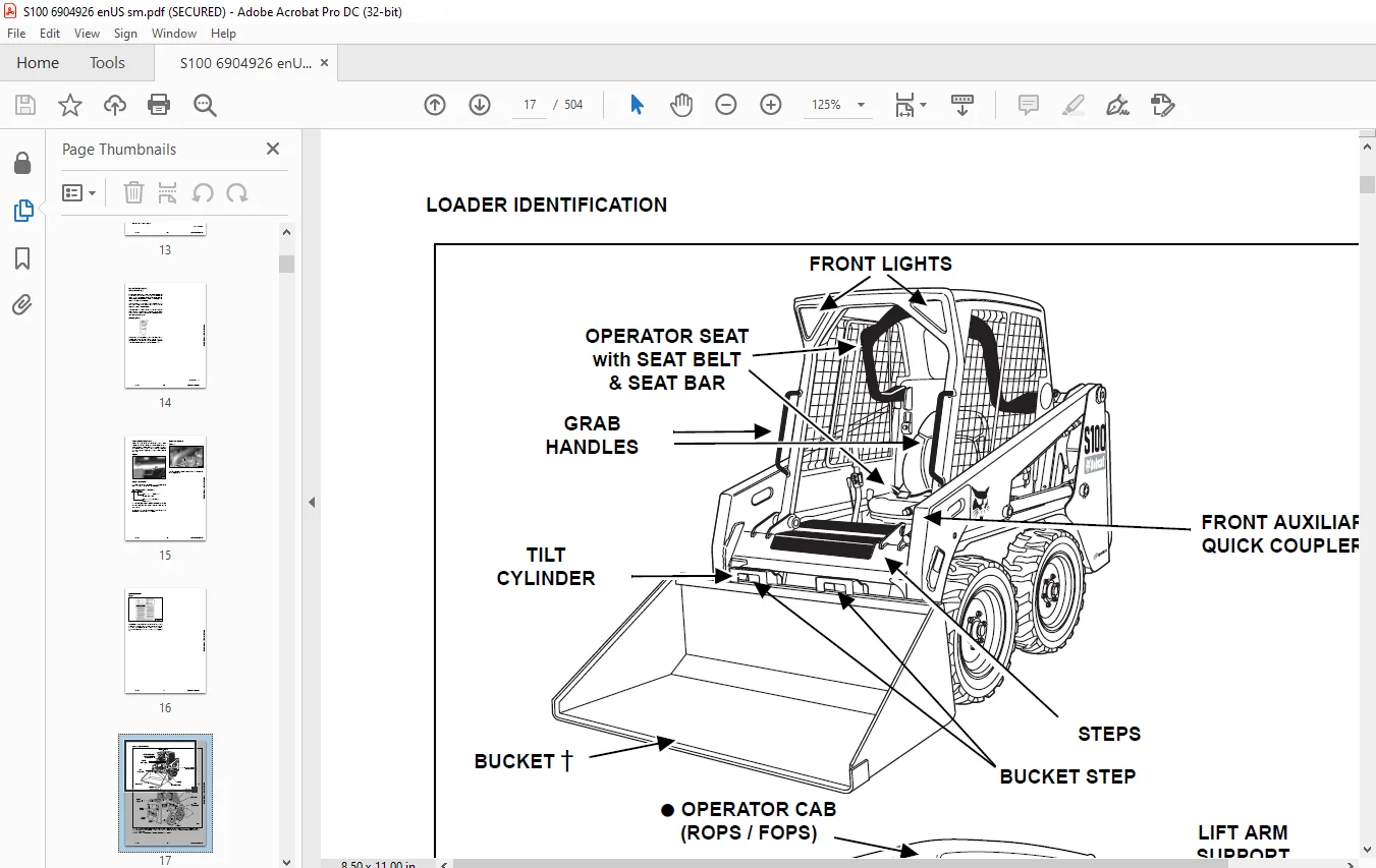
LOADER IDENTIFICATION 17
SAFETY AND MAINTENANCE 19
LIFTING AND BLOCKING THE LOADER 23
Procedure 23
LIFT ARM SUPPORT DEVICE 25
Installing 25
Removing 26
OPERATOR CAB 27
Description 27
Raising 27
Lowering 28
Cab Door Sensor 29
TRANSPORTING THE LOADER ON A TRAILER 31
Loading And Unloading 31
Fastening 31
TOWING THE LOADER 33
Procedure 33
REMOTE START TOOL KIT-MEL1563 35
Remote Start Tool – MEL1563 35
Service Tool Harness Control – MEL1565 36
Service Tool Harness Communicator – MEL1566 37
Remote Start Procedure 38
REMOTE START TOOL (SERVICE TOOL) KIT – 7003031 41
Description 41
Remote Start Tool (Service Tool) – 7003030 42
Loader Service Tool Harness – 6689747 43
Computer Service Tool Harness – 6689746 44
Remote Start Procedure 45
SERVICE SCHEDULE 49
Chart 49
AIR CLEANER SERVICE 51
Replacing Filter Elements 51
ENGINE COOLING SYSTEM 55
Cleaning 55
Checking Level 55
Removing And Replacing Coolant 56
FUEL SYSTEM 57
Fuel Specifications 57
Biodiesel Blend Fuel 57
Filling The Fuel Tank 58
Fuel Filter 59
Removing Air From The Fuel System 59
ENGINE LUBRICATION SYSTEM 61
Checking And Adding Engine Oil 61
Engine Oil Chart 61
Removing And Replacing Oil And Filter 61
HYDRAULIC / HYDROSTATIC SYSTEM 63
Checking And Adding Fluid 63
Hydraulic / Hydrostatic Fluid Chart 63
Removing And Replacing Hydraulic Fluid 64
Removing And Replacing Hydraulic / Hydrostatic Filter 65
Removing And Replacing Case Drain Filters 66
Removing And Replacing Hydraulic Charge Filter 67
Breather Cap 67
FINAL DRIVE TRANSMISSION (CHAINCASE) 69
Checking And Adding Oil 69
Removing And Replacing Oil 69
BOB-TACH (HAND LEVER) 71
Inspection And Maintenance 71
LUBRICATING THE LOADER 73
Lubrication Locations 73
TIRE MAINTENANCE 75
Wheel Nuts 75
Rotating 75
Mounting 75
SPARK ARRESTOR MUFFLER 77
Cleaning Procedure 77
PIVOT PINS 79
Inspection And Maintenance 79
LOADER STORAGE AND RETURN TO SERVICE 81
Storage 81
Return To Service 81
STOPPING THE ENGINE AND LEAVING THE LOADER 83
Procedure 83
Emergency Exit 84
HYDRAULIC SYSTEM 85
HYDRAULIC / HYDROSTATIC SCHEMATIC 87
HYDRAULIC SYSTEM INFORMATION 89
Glossary Of Hydraulic / Hydrostatic Symbols 89
Troubleshooting 93
CYLINDER (LIFT) 95
Testing 95
Removal And Installation 96
Parts Identification 97
Disassembly And Assembly 98
CYLINDER (TILT) 101
Testing 101
Removal And Installation 101
Parts Identification 103
Disassembly And Assembly 104
MAIN RELIEF VALVE 107
Description 107
Testing 107
Adjusting 108
Removal And Installation 108
HYDRAULIC CONTROL VALVE 109
Description 109
Removal And Installation 109
Identification Chart 112
Load Check Valve Removal And Installation (Tilt and Auxiliary) 113
Anti-Cavitation Valve Removal And Installation (Lift, Rod End) 114
Port Relief / Anti-Cavitation Valve Removal And Installation (Lift, Base End) 115
Port Relief / Anti-Cavitation Valve Removal And Installation (Tilt, Base End) 115
Port Relief / Anti-Cavitation Valve Removal And Installation (Tilt, Rod End) 116
Port Relief Valve Removal And Installation 116
Rubber Boot Removal And Installation 117
End Cap / Spool Lock Block Removal And Installation 117
Lift Spool And Detent Removal And Installation 118
Tilt Spool Removal And Installation 127
Auxiliary Spool Removal And Installation 129
Solenoid Removal And Installation 137
Lock Valve Removal And Installation 138
Main Relief Valve Removal And Installation 140
LIFT ARM bypass CONTROL VALVE 141
Description 141
Testing 141
Removal and Installation 141
Disassembly And Assembly 143
HYDRAULIC PUMP 145
Description 145
Pump Test at Quick Couplers 145
Direct Pump Test 146
Direct Pump Test (Charge Section) 147
Removal And Installation 150
Parts Identification 153
Disassembly And Assembly 154
Hydraulic Pump Start Up 158
HYDRAULIC / HYDROSTATIC FILTERS 159
Description 159
Hydraulic / Hydrostatic Filter Housing Removal And Installation 159
HYDRAULIC FLUID RESERVOIR 161
Description 161
Removal And Installation 161
Hydraulic Fluid Screen 162
OIL COOLER 163
Description 163
Removal And Installation 163
BUCKET POSITION VALVE 165
Description 165
Solenoid Removal And Installation 165
Solenoid Testing 166
Removal And Installation 166
Disassembly And Assembly 169
FRONT AUXILIARY HYDRAULIC COUPLERS 171
Description 171
Removal And Installation 171
HYDROSTATIC SYSTEM 173
HYDROSTATIC SYSTEM INFORMATION 175
Description 175
Troubleshooting 176
HYDROSTATIC MOTOR 177
Description 177
Removal And Installation 177
Parts Identification 179
Disassembly And Assembly 180
CHARGE PRESSURE 185
Description 185
Testing 185
Sender Removal And Installation 186
Adjusting 187
HYDROSTATIC PUMP 189
Description 189
Replenishing / High Pressure Relief Valve Removal And Installation 189
Removal And Installation 190
Hydrostatic Pump Start Up 192
Parts Identification 193
Disassembly 194
Assembly 199
DRIVE BELT 205
Description 205
Shield Removal And Installation 205
Adjusting 205
Belt Removal And Installation 206
Tensioner Pulley Removal And Installation 206
Tensioner Pulley Disassembly And Assembly 206
DRIVE SYSTEM 207
BRAKE 209
Description 209
Disk Removal And Installation 209
DRIVE COMPONENTS 211
Description 211
Axle Seal Removal And Installation 212
Axle Sprocket And Bearings Removal And Installation 214
Chain Removal And Installation 218
CHAINCASE 221
Description 221
Front Cover Removal And Installation 221
Center Cover Removal And Installation 222
MAIN FRAME 225
SEAT BAR 229
Description 229
Removal And Installation 229
Disassembly And Assembly 231
Compression Spring Disassembly And Assembly 232
OPERATOR CAB 233
Gas Cylinder Removal And Installation 233
Gas Cylinder Bracket Disassembly And Assembly 235
Removal And Installation 236
OPERATOR SEAT 239
Removal And Installation 239
Seat Belt Removal And Installation 239
OPERATOR SEAT (SUSPENSION) 241
Removal And Installation 241
Slide Rail Removal And Installation 242
Seat Belt Removal and Installation 242
Lower Cushion Removal And Installation 243
Back Cushion Removal And Installation 243
Shock Removal And Installation 244
3-Point Seat Belt Removal And Installation 244
BOB-TACH (HAND LEVER) 247
Description 247
Removal And Installation 247
Lever And Wedge Disassembly And Assembly 249
Pivot Pin Bushing And Seal Removal And Installation 250
LIFT ARMS 251
Removal And Installation 251
REAR GRILL 257
Removal And Installation 257
REAR DOOR 259
Removal And Installation 259
Striker Removal and Installation 260
Striker Disassembly and Assembly 260
Striker (Adjusting) 260
Latch Removal And Installation 261
FUEL TANK 263
Removal And Installation 263
Fuel Level Sender Removal And Installation 264
Fuel Fill Screen Removal And Installation 264
Fuel Pickup Screen 264
CONTROL PEDALS AND LINKAGES 265
Description 265
Pedal Removal And Installation 265
Linkage Removal And Installation 266
Pedal (Adjusting) 266
CONTROL PANEL 269
Description 269
Removal and Installation 270
Shaft Removal And Installation 273
Shaft Disassembly And Assembly 273
Linkage Removal And Installation 274
Pintle Arm Removal And Installation 275
Pintle Arm Disassembly and Assembly 278
Linkage Neutral Adjusting 279
Linkage Travel Adjusting 282
CONTROL HANDLE / LEVER 287
Description 287
Lever Removal And Installation 287
Boot Removal And Installation 287
WINDOW (REAR) 289
Removal 289
Installation 289
WINDOW (TOP) 291
Removal And Installation 291
WINDOW (SIDE) 293
Removal And Installation 293
WINDOW (FRONT DOOR) 295
Removal (Standard Window) 295
Installation (Standard Window) 296
Removal And Installation (Special Applications Window) 297
ELECTRICAL SYSTEM & ANALYSIS 299
ELECTRICAL SCHEMATICS 303
ELECTRICAL SYSTEM INFORMATION 305
Glossary Of Electrical Symbols 305
Cab Harness Connectors 308
Mainframe Harness Connectors 309
Description 310
Troubleshooting 311
Fuse And Relay Location / Identification 312
Solenoid Testing 313
BATTERY 315
Removal And Installation 315
Servicing 316
Using A Booster Battery (Jump Starting) 317
ALTERNATOR 319
Belt Adjustment 319
Charging System Inspection 319
Alternator Voltage Testing 320
Low Voltage Testing 321
High Voltage Testing 321
Removal And Installation 322
Parts Identification 324
STARTER 325
Testing 325
Removal And Installation 326
Parts Identification 327
INSTRUMENT PANELS 329
Left Panel 329
Display Screen 330
Standard Key Panel 330
Option And Field Accessory Panels 331
Removal And Installation (Left And Right) 332
Key Switch Removal And Installation 333
Alarm Removal And Installation 333
Front Accessory Panel Removal And Installation 334
LIGHTS 335
Front Removal And Installation 335
Rear Removal And Installation 335
Cab Light Removal And Installation 336
BOBCAT CONTROLLER (MAIN) 337
Description 337
Connector Identification 338
Removal And Installation 340
DIAGNOSTIC SERVICE CODES 341
Viewing Service Codes (Standard Key Panel) 341
Service Codes List 342
BOBCAT INTERLOCK CONTROL SYSTEM (BICS) 347
Description 347
Inspecting The BICS Controller (Engine STOPPED – Key ON) 347
Inspecting The Seat Bar Sensor (Engine RUNNING) 347
Inspecting The Traction Lock (Engine RUNNING) 347
Inspecting The Lift Arm Bypass Control 348
Troubleshooting 349
Troubleshooting Chart 350
SEAT BAR SENSOR 351
Description 351
Troubleshooting 351
Testing 352
Removal And Installation 353
Bobcat Interlock Control System (BICS) Circuit Test 355
TRACTION LOCK 357
Description 357
Troubleshooting 357
Removal And Installation 358
Inspecting 361
SERVICE PC (LAPTOP COMPUTER) 363
Connecting To The Remote Start Tool 363
Connecting Remote Start Tool (Service Tool) 363
FLYWHEEL RPM SENSOR 365
Description 365
Adjusting 365
MAINTENANCE CLOCK 367
Description 367
Setup 368
Reset 371
BACK-UP ALARM SYSTEM 373
Description 373
Inspecting 373
Adjusting Switch Position 374
Troubleshooting 375
Alarm Removal And Installation 376
Switch Removal And Installation 376
ENGINE SERVICE 379
ENGINE INFORMATION 381
Description 381
Specifications 382
Torque Values 386
Troubleshooting 388
Engine Removal And Installation 389
Engine Mount Replacement 397
Compression-Checking 398
ENGINE SPEED CONTROL 399
Removal And Installation 399
MUFFLER 401
Removal And Installation 401
AIR CLEANER 403
Removal And Installation 403
ENGINE COOLING SYSTEM 405
Radiator Removal And Installation 405
Fan Removal And Installation 406
Water Pump Removal And Installation 406
Water Pump Disassembly And Assembly 407
Thermostat Housing Removal And Installation 407
Testing The Thermostat 408
LUBRICATION SYSTEM 409
Oil Pan Removal And Installation 409
Oil Pump Removal And Installation 409
Oil Pump Inspection 410
Engine Oil Pressure – Testing 411
FUEL SYSTEM 413
Fuel Camshaft Removal And Installation 413
Fuel Camshaft Governor Disassembly And Assembly 413
Fuel Shutoff Solenoid – Checking 414
Fuel Shutoff Solenoid Removal And Installation 415
Fuel Injection Pump Removal And Installation 416
Timing The Injection Pump 418
Fuel Injector Removal And Installation 420
Fuel Injector Nozzles Pressure – Checking 421
Nozzle Spray Condition 422
Valve Seat Tightness 423
CYLINDER HEAD 425
Glow Plug – Testing 425
Glow Plug Removal And Installation 426
Valve Clearance Adjustment 426
Valve Timing – Checking 427
Cylinder Head Removal And Installation 428
Cylinder Head Disassembly and Assembly 430
Cylinder Head – Servicing 430
Cylinder Head Top Clearance 431
Valve Guide – Checking 431
Reconditioning The Valve And Valve Seat 432
Valve Spring 434
Valve Tappets 434
Rocker Arm And Shaft – Checking 435
CRANKSHAFT AND PISTONS 437
Piston And Connecting Rod Removal And Installation 437
Piston And Connecting Rod – Servicing 438
Cylinder Bore Checking 440
Connecting Rod Alignment 441
Crankshaft And Bearings Removal And Installation 441
Crankshaft And Bearings – Servicing 443
CAMSHAFT AND TIMING GEARS 449
Timing Gearcase Cover Removal And Installation 449
Timing Gears Backlash – Checking 451
Idler Gear And Shaft Removal And Installation 451
Camshaft – Servicing 452
Idler Gear And Shaft Servicing 454
FLYWHEEL 455
Flywheel Removal And Installation 455
HEATER 457
HEATER SYSTEM 459
Description 459
REGULAR MAINTENANCE 461
Filter Elements Removal And Installation 461
Cleaning The Heater Coil 462
TROUBLESHOOTING 463
Blower Motor Does Not Operate 463
Blower Motor Operators Normally, But Air Flow Is Insufficient 463
Electrical System 464
Engine Coolant bypassing The Heater Valve 468
Heater Valve Not Opening Or Closing 468
HEATER UNIT 471
Removal And Installation 471
HEATER COIL 473
Removal And Installation 473
HEATER FAN 475
Blower Removal And Installation 475
Disassembly And Assembly 476
Connector Identification 478
HEATER VALVE 479
Removal and Installation 479
Disassembly And Assembly 480
SPECIFICATIONS 481
(S100) LOADER SPECIFICATIONS 483
Dimensions 483
Performance 484
Controls 484
Engine 485
Hydraulic System 485
Electrical 486
Drive System 486
Capacities 487
Tires 487
TORQUE SPECIFICATIONS FOR BOLTS 489
Torque For General SAE Bolts 489
Torque For General Metric Bolts 490
HYDRAULIC CONNECTION SPECIFICATIONS 491
O-ring Face Seal Connection 491
Straight Thread O-ring Fitting 492
Tubelines And Hoses 492
Flare Fitting 492
Port Seal Fitting 493
HYDRAULIC / HYDROSTATIC FLUID SPECIFICATIONS 495
Specifications 495
CONVERSIONS 497
Decimal And Millimeter Equivalent Chart 497
U S To Metric Conversion Chart 497
SMR 499
S100-1 499
S100-2 501
S100-3 503
IMAGES PREVIEW OF THE MANUAL:
Questions? Email us: [email protected]
https://vimeo.com/843182634?share=copy
PLEASE NOTE:
- This is the same manual used by the DEALERSHIPS to SERVICE your vehicle.
- The manual can be all yours – Once payment is complete, you will be taken to the download page from where you can download the manual. All in 2-5 minutes time!!
- Need any other service / repair / parts manual, please feel free to contact us at heydownloadss @gmail.com . We may surprise you with a nice offer
S.V