Bobcat S100 Skid-Steer Loader Service Manual SN A8ET20001 & Above – PDF DOWNLOAD
$31.95
Bobcat S100 Skid-Steer Loader Service Manual SN A8ET20001 & Above – PDF DOWNLOAD
Description
Bobcat S100 Skid-Steer Loader Service Manual SN A8ET20001 & Above – PDF DOWNLOAD
FILE DETAILS:
Bobcat S100 Skid-Steer Loader Service Manual SN A8ET20001 & Above – PDF DOWNLOAD
Language : English
Pages : 692
Downloadable : Yes
File Type : PDF
DESCRIPTION:
Bobcat S100 Skid-Steer Loader Service Manual SN A8ET20001 & Above – PDF DOWNLOAD
FOREWORD:
This manual is for the Bobcat loader mechanic. It provides necessary servicing and adjustment procedures for the Bobcat loader and its component parts and systems. Refer to the Operation & Maintenance Manual for operating instructions, starting procedure, daily checks, etc.
A general inspection of the following items must be made after the loader has had service or repair:
Before Operation:
- Carefully follow the operating and maintenance instructions in this manual.
- The Bobcat loader is highly maneuverable and compact. It is rugged and useful under a wide variety of conditions. This presents an operator with hazards associated with off motorway, rough terrain applications, common with Bobcat loader usage.
- The Bobcat loader has an internal combustion engine with resultant heat and exhaust. All exhaust gases can kill or cause illness so use the Loader with adequate ventilation.
- The dealer explains the capabilities and restrictions of the Bobcat loader and attachment for each application. The dealer demonstrates the safe operation according to Bobcat instructional materials, which are also available to operators. The dealer can also identify unsafe modifications or use of unapproved attachments. The attachments and buckets are designed for a Rated Operating Capacity (some have restricted lift heights). They are designed for secure fastening to the Bobcat loader. The user must check with the dealer, or Bobcat literature, to determine safe loads of materials of specified densities for the machine – attachment combination.
TABLE OF CONTENTS:
Bobcat S100 Skid-Steer Loader Service Manual SN A8ET20001 & Above – PDF DOWNLOAD
MAINTENANCE SAFETY 3
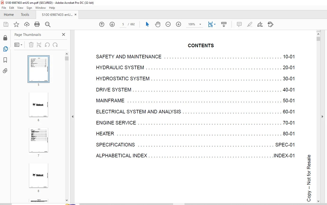
CONTENTS 5
FOREWORD 7
FOREWORD 9
SAFETY INSTRUCTIONS 12
Before Operation 12
Safe Operation Is The Operator’s Responsibility 13
Safe Operation Needs A Qualified Operator 13
Avoid Silica Dust 14
FIRE PREVENTION 14
Maintenance 14
Operation 14
Electrical 14
Hydraulic System 15
Fueling 15
Starting 15
Spark Arrester Exhaust System 15
Welding And Grinding 15
Fire Extinguishers 15
SERIAL NUMBER LOCATIONS 16
Loader Serial Number 16
Engine Serial Number 16
DELIVERY REPORT 17
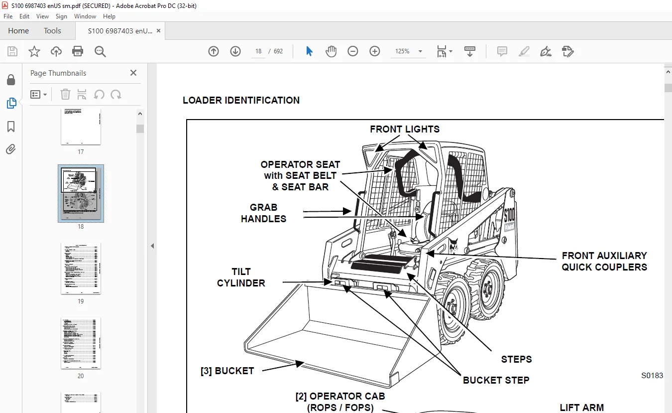
LOADER IDENTIFICATION 18
SAFETY AND MAINTENANCE 19
LIFTING AND BLOCKING THE LOADER 23
Procedure 23
LIFT ARM SUPPORT DEVICE 25
Installing 25
Removing 26
OPERATOR CAB 27
Description 27
Raising 27
Lowering 28
Cab Door Sensor 29
Special Applications Kit 30
Special Applications Kit Inspection And Maintenance 30
TRANSPORTING THE LOADER ON A TRAILER 31
Loading And Unloading 31
Fastening 31
TOWING THE LOADER 33
Procedure 33
REMOTE START TOOL KIT-MEL1563 35
Remote Start Tool – MEL1563 35
Service Tool Harness Control – MEL1565 36
Service Tool Harness Communicator – MEL1566 37
Remote Start Procedure 38
REMOTE START TOOL (SERVICE TOOL) KIT – 7217666 41
Description 41
Remote Start Tool (Service Tool) – 7022042 42
Loader Service Tool Harness – 6689747 43
Computer Service Tool Harness – 6689746 44
Remote Start Procedure 45
SERVICE SCHEDULE 49
Chart 49
AIR CLEANER SERVICE 51
Replacing Filter Elements 51
ENGINE COOLING SYSTEM 53
Cleaning 53
Checking Level 53
Removing And Replacing Coolant 54
FUEL SYSTEM 55
Fuel Specifications 55
Biodiesel Blend Fuel 55
Filling The Fuel Tank 56
Fuel Filter 57
Removing Air From The Fuel System 57
ENGINE LUBRICATION SYSTEM 59
Checking And Adding Engine Oil 59
Engine Oil Chart 59
Removing And Replacing Oil And Filter 60
HYDRAULIC / HYDROSTATIC SYSTEM 61
Checking And Adding Fluid 61
Hydraulic / Hydrostatic Fluid Chart 61
Removing And Replacing Hydraulic Fluid 62
Removing And Replacing Hydraulic / Hydrostatic Filter 63
Removing And Replacing Case Drain Filters 64
Removing And Replacing Hydraulic Charge Filter 65
Breather Cap 65
FINAL DRIVE TRANSMISSION (CHAINCASE) 67
Checking And Adding Oil 67
Removing And Replacing Oil 67
BOB-TACH (HAND LEVER) 69
Inspection And Maintenance 69
BOB-TACH (POWER) 71
Inspection And Maintenance 71
LUBRICATING THE LOADER 73
Lubrication Locations 73
TIRE MAINTENANCE 75
Wheel Nuts 75
Rotating 75
Mounting 75
SPARK ARRESTER MUFFLER 77
Cleaning Procedure 77
PIVOT PINS 79
Inspection And Maintenance 79
LOADER STORAGE AND RETURN TO SERVICE 81
Storage 81
Return To Service 81
STOPPING THE ENGINE AND LEAVING THE LOADER 83
Procedure 83
EMERGENCY EXIT 85
Rear Window 85
Front Door 85
SEAT BELT 87
Inspection And Maintenance 87
HYDRAULIC SYSTEM 89
HYDRAULIC / HYDROSTATIC SCHEMATICS 93
HYDRAULIC SYSTEM INFORMATION 97
Glossary Of Hydraulic / Hydrostatic Symbols 97
Troubleshooting 101
CYLINDER (LIFT) 103
Testing 103
Removal And Installation 104
Parts Identification 105
Disassembly And Assembly 106
CYLINDER (TILT) 109
Testing 109
Removal And Installation 109
Rod End Pivot Pin Bushing And Seal Removal And Installation 111
Base End Pivot Pin Removal And Installation 111
Parts Identification 112
Disassembly And Assembly 113
CYLINDER (BOB-TACH) 117
Testing 117
Removal And Installation 118
Parts Identification 119
Disassembly And Assembly 120
MAIN RELIEF VALVE 123
Description 123
Testing 123
Adjusting 124
Removal And Installation 124
MAIN RELIEF VALVE (SJC) 125
Description 125
Testing 125
Adjusting 126
Removal And Installation 127
HYDRAULIC CONTROL VALVE 129
Description 129
Removal And Installation 129
Identification Chart 131
BICS™ Load Check Valve Removal And Installation 132
Load Check Valve Removal And Installation (Tilt And Auxiliary) 133
Anti-Cavitation Valve Removal And Installation (Lift, Rod End) 134
Port Relief / Anti-Cavitation Valve Removal And Installation (Lift, Base End) 135
Port Relief / Anti-Cavitation Valve Removal And Installation (Tilt, Base End) 135
Port Relief / Anti-Cavitation Valve Removal And Installation (Tilt, Rod End) 136
Port Relief Valve Removal And Installation 136
Plug Removal And Installation 137
Rubber Boot Removal And Installation 137
End Cap / Spool Lock Block Removal And Installation 138
Lift Spool And Detent Removal And Installation 138
Tilt Spool Removal And Installation 147
Auxiliary Spool Removal And Installation 150
Solenoid Removal And Installation 157
Lock Valve Removal And Installation 158
Lift Arm Bypass Orifice Removal And Installation 160
Main Relief Valve Removal And Installation 161
HYDRAULIC CONTROL VALVE (SJC) 163
Description 163
Removal And Installation 163
Actuator Removal And Installation 166
Identification Chart 169
BICS™ Load Check Valve Removal And Installation 170
Load Check Valve Removal And Installation (Tilt And Auxiliary) 171
Anti-Cavitation Valve Removal And Installation (Lift, Rod End) 172
Port Relief / Anti-Cavitation Valve Removal And Installation (Lift, Base End) 173
Port Relief / Anti-Cavitation Valve Removal And Installation (Tilt, Base End) 173
Port Relief / Anti-Cavitation Valve Removal And Installation (Tilt, Rod End) 174
Port Relief / Anti-Cavitation Valve Removal And Installation 174
Plug Removal And Installation 175
End Cap Block Removal And Installation 176
Lift Spool And Detent Removal And Installation 176
Tilt Spool Removal And Installation 180
Auxiliary Spool Removal And Installation 182
Auxiliary Solenoid Removal And Installation 184
Solenoid Removal And Installation 185
Lock Valve Removal And Installation 186
Lift Arm Bypass Orifice Removal And Installation 187
Main Relief Valve Removal And Installation 188
Check Valve Removal And Installation 188
LIFT ARM BYPASS CONTROL VALVE 191
Description 191
Testing 191
Removal And Installation 191
Disassembly And Assembly 193
HYDRAULIC PUMP 195
Description 195
Pump Test At Quick Couplers 195
Direct Pump Test (Standard Section) 196
Direct Pump Test (Charge Section) 197
Removal And Installation 200
Hydraulic Pump Start Up 202
Parts Identification 203
Disassembly And Assembly 204
HYDRAULIC PUMP (SJC) 209
Description 209
Pump Test At Quick Couplers 209
Direct Pump Test (Standard Section) 210
Removal And Installation 211
Hydraulic Pump Start Up 212
Parts Identification 213
Disassembly And Assembly 214
HYDRAULIC / HYDROSTATIC FILTERS 219
Description 219
Housing Removal And Installation 219
Charge Filter Housing Removal And Installation 220
HYDRAULIC FLUID RESERVOIR 221
Description 221
Removal And Installation 221
Hydraulic Fluid Screen 223
OIL COOLER 225
Description 225
Removal And Installation 225
BUCKET POSITION VALVE 227
Description 227
Solenoid Removal And Installation 227
Solenoid Testing 228
Removal And Installation 228
Disassembly And Assembly 231
FRONT AUXILIARY HYDRAULIC COUPLER BLOCK 233
Description 233
Removal And Installation 233
FRONT AUXILIARY HYDRAULIC COUPLER BLOCK (SJC) 235
Description 235
Removal And Installation 235
Disassembly And Assembly 235
AUXILIARY HYDRAULIC INTERLOCK VALVE 237
Description 237
Removal And Installation 237
Disassembly And Assembly 238
BOB-TACH (POWER) BLOCK 239
Description 239
Removal And Installation 239
Disassembly And Assembly 241
HYDROSTATIC SYSTEM 245
HYDROSTATIC SYSTEM INFORMATION 247
Description 247
Troubleshooting 248
HYDROSTATIC MOTOR 249
Description 249
Removing And Replacing Oil 249
Removal And Installation 249
Parts Identification 251
Disassembly And Assembly 252
CHARGE PRESSURE 257
Description 257
Testing 257
Sender Removal And Installation 258
Adjusting 259
HYDROSTATIC PUMP 261
Description 261
Replenishing / High Pressure Relief Valve Removal And Installation 261
Removal And Installation 262
Hydrostatic Pump Startup 264
Parts Identification 265
Disassembly 266
Assembly 271
HYDROSTATIC PUMP (SJC) 277
Description 277
High Pressure Relief And Bypass Valve 278
Removal And Installation 279
Hydrostatic Pump Start Up 281
Hydraulic Controller Removal And Installation 282
Parts Identification 284
Disassembly And Assembly 285
Mechanical Neutral Adjustment 300
Hydraulic Controller Neutral Adjustment 303
DRIVE BELT 307
Description 307
Shield Removal And Installation 307
Adjusting 307
Belt Removal And Installation 308
Tensioner Pulley Removal And Installation 308
Tensioner Pulley Disassembly And Assembly 308
CASE DRAIN FILTER 309
Description 309
Disassembly And Assembly 309
DRIVE SYSTEM 311
BRAKE 313
Description 313
Disc Removal And Installation 313
DRIVE COMPONENTS 315
Description 315
Axle Seal Removal And Installation 316
Axle, Sprocket And Bearings Removal And Installation 318
Chain Removal And Installation 322
CHAINCASE 325
Description 325
Front Cover Removal And Installation 325
Center Cover Removal And Installation 326
MAINFRAME 329
SEAT BAR 333
Description 333
Removal And Installation 333
Disassembly And Assembly 334
Compression Spring Disassembly And Assembly 335
OPERATOR CAB 337
Gas Cylinder Removal And Installation 337
Gas Cylinder Bracket Disassembly And Assembly 339
Removal And Installation 340
OPERATOR SEAT 343
Removal And Installation 343
Seat Belt Removal And Installation 343
OPERATOR SEAT (SUSPENSION) 345
Removal And Installation 345
Slide Rail Removal And Installation 346
Seat Belt Removal And Installation 346
Lower Cushion Removal And Installation 347
Back Cushion Removal And Installation 347
Shock Removal And Installation 348
3-Point Seat Belt Removal And Installation 348
BOB-TACH (HAND LEVER) 351
Description 351
Removal And Installation 351
Lever And Wedge Disassembly And Assembly 353
Bob-Tach Stops 355
Pivot Pin Bushing And Seal Removal And Installation 355
BOB-TACH (POWER) 357
Description 357
Removal And Installation 357
Lever And Wedge Disassembly And Assembly 359
Bob-Tach Stops 360
Pivot Pin Bushing And Seal Removal And Installation 361
LIFT ARMS 363
Removal And Installation 363
REAR GRILLE 369
Removal And Installation 369
REAR DOOR 371
Removal And Installation 371
Striker Removal And Installation 372
Striker Disassembly And Assembly 372
Striker (Adjusting) 373
Latch Removal And Installation 374
FUEL TANK 375
Removal And Installation 375
Fuel Level Sender Removal And Installation 376
Fuel Fill Screen Removal And Installation 376
Fuel Pickup Screen 376
CONTROL PEDALS AND LINKAGES 377
Description 377
Pedal Removal And Installation 377
Linkage Removal And Installation 378
Pedal (Adjusting) 378
CONTROL PANEL 379
Description 379
Removal And Installation 380
Shaft Removal And Installation 383
Shaft Disassembly And Assembly 383
Shock Removal And Installation 384
Linkage Removal And Installation 384
Pintle Arm Removal And Installation 385
Pintle Arm Disassembly And Assembly 388
Linkage Neutral (Adjusting) 389
Linkage Travel (Adjusting) 392
CONTROL PANEL (SJC) 397
Description 397
Removal And Installation 397
CONTROL HANDLE / LEVER (STANDARD) 399
Description 399
Lever Removal And Installation 399
Boot Removal And Installation 399
CONTROL HANDLE / LEVER (SJC) 401
Description 401
Joystick Testing 401
Joystick Removal And Installation 402
Joystick Mount Removal And Installation 403
WINDOWS (REAR) 405
Removal 405
Installation 405
WINDOWS (TOP) 407
Removal And Installation 407
WINDOWS (SIDE) 409
Removal And Installation 409
WINDOWS (CAB DOOR) 411
Removal (Standard Window) 411
Installation (Standard Window) 412
Removal And Installation (Special Applications Window) 413
CAB DOOR 415
Description 415
Removal And Installation 415
Aligning 416
Adjusting 417
Checking Operation 417
CAB DOOR (SPECIAL APPLICATIONS KIT DOOR) 419
Description 419
Removal And Installation 419
Aligning 420
Adjusting 421
Checking Operation 421
ELECTRICAL SYSTEM AND ANALYSIS 423
ELECTRICAL SCHEMATICS 427
ELECTRICAL SYSTEM INFORMATION 431
Glossary Of Electrical Symbols 431
Standard Cab Harness Connectors 434
Deluxe Cab Harness Connectors 435
Mainframe Harness Connectors 436
Description 437
Troubleshooting 438
Fuse And Relay Location / Identification 439
Solenoid Testing 440
BATTERY 441
Removal And Installation 441
Servicing 442
Using A Booster Battery (Jump Starting) 443
ALTERNATOR 445
Belt Adjustment 445
Belt Replacement 445
Charging System Inspection 446
Alternator Voltage Testing 447
Low Voltage Testing 447
High Voltage Testing 448
Removal And Installation 448
Parts Identification 450
STARTER 451
Testing 451
Removal And Installation 452
Parts Identification 453
INSTRUMENT PANELS 455
Left Panel 455
Standard Key Panel 457
Keyless Start Panel 457
Deluxe Instrumentation Panel 458
Side Panel 459
Front Panel 459
Front Panel Removal And Installation 460
Removal And Installation (Left And Right) 460
Key Switch Removal And Installation 461
Alarm Removal And Installation 462
LIGHTS 463
Front Removal And Installation 463
Rear Removal And Installation 463
Cab Light Removal And Installation 464
BOBCAT CONTROLLER (GATEWAY) 465
Description 465
Connector Identification 466
Removal And Installation 469
BOBCAT CONTROLLER (AUXILIARY) (SJC) 471
Description 471
Connector Identification 472
Removal And Installation 475
BOBCAT CONTROLLER (ACS) (SJC) 477
Description 477
Connector And Wire Identification 478
Removal And Installation 479
BOBCAT CONTROLLER (DRIVE) (SJC) 481
Description 481
Connector Identification 482
Removal And Installation 484
DIAGNOSTIC SERVICE CODES 487
Viewing Service Codes 487
Service Codes List 488
BOBCAT INTERLOCK CONTROL SYSTEM (BICS™) 493
Description 493
Inspecting The BICS™ (Engine STOPPED – Key ON) 494
Inspecting Deactivation Of The Auxiliary Hydraulics System (Engine STOPPED – Key ON) 494
Inspecting The Seat Bar Sensor (Engine RUNNING) 494
Inspecting The Traction Lock (Engine RUNNING) 494
Inspecting The Lift Arm Bypass Control 494
Inspecting Deactivation Of Lift And Tilt Functions (SJC) 494
Troubleshooting 495
SEAT BAR SENSOR 497
Description 497
Troubleshooting 497
Testing 498
Removal And Installation 499
Bobcat Interlock Control System (BICS™) Circuit Test 502
TRACTION LOCK 503
Description 503
Troubleshooting 503
Removal And Installation 504
Inspecting 507
ELECTRICAL / HYDRAULIC CONTROLS (SJC) 509
Identification Chart 509
SERVICE PC (LAPTOP COMPUTER) 513
Connecting Remote Start Tool 513
Connecting Remote Start Tool (Service Tool) 513
CALIBRATION 515
Description 515
Actuator Testing 515
Lift And Tilt Calibration (SJC) 517
Hydrostatic Pump Calibration (SJC) 519
STEERING DRIFT COMPENSATION 525
Description 525
Operation 525
FLYWHEEL RPM SENSOR 527
Description 527
Adjusting 527
CONTROL PANEL SETUP 529
Right Panel Setup (Deluxe Instrumentation Panel) 529
Attachment Control Information (Deluxe Instrumentation Panel) 530
PASSWORD SETUP (DELUXE INSTRUMENTATION PANEL) 531
Password Description 531
Changing The Owner Password 531
Changing The User Passwords 532
Password Lockout Feature 532
PASSWORD SETUP (KEYLESS START PANEL) 533
Password Description 533
Changing The Owner Password 533
Password Lockout Feature 533
MAINTENANCE CLOCK 535
Description 535
Setup 536
Reset 539
BACK-UP ALARM SYSTEM 541
Description 541
Inspecting 541
Adjusting Switch Position 541
Troubleshooting (Standard) 542
Troubleshooting (Joystick) 543
Alarm Removal And Installation 544
Switch Removal And Installation 544
ENGINE SERVICE 547
ENGINE INFORMATION 549
Description 549
Specifications 550
Torque Values 554
Troubleshooting 555
Engine Removal And Installation 556
Engine Mount Replacement 568
Compression – Checking 569
ENGINE SPEED CONTROL 571
Removal And Installation 571
ENGINE SPEED CONTROL (SJC) 573
Removal And Installation 573
Disassembly And Assembly 575
MUFFLER 577
Removal And Installation 577
AIR CLEANER 579
Housing Removal And Installation 579
ENGINE COOLING SYSTEM 581
Radiator Removal And Installation 581
Fan Removal And Installation 582
Water Pump Removal And Installation 583
Water Pump Disassembly And Assembly 583
Thermostat Housing Removal And Installation 584
Thermostat – Checking 584
LUBRICATION SYSTEM 585
Oil Pan Removal And Installation 585
Oil Pump Removal And Installation 585
Oil Pump Inspection 586
Engine Oil Pressure – Testing 587
FUEL SYSTEM 589
Fuel Shutoff Solenoid – Checking 589
Fuel Shutoff Solenoid Removal And Installation 589
Fuel Injection Pump – Checking 590
Fuel Injection Pump Removal And Installation 591
Governor Disassembly And Assembly 593
Fuel Camshaft Removal And Installation 594
Fuel Injection Pump – Timing 595
Fuel Injector Removal And Installation 597
Fuel Injector Nozzle Pressure – Checking 598
Nozzle Spray Condition 599
Valve Seat Tightness 600
CYLINDER HEAD 601
Glow Plug – Testing 601
Glow Plug Removal And Installation 602
Valve Clearance Adjustment 602
Valve Timing – Checking 603
Cylinder Head Removal And Installation 604
Cylinder Head Disassembly And Assembly 606
Cylinder Head – Servicing 606
Cylinder Head Top Clearance 607
Valve Guide – Checking 607
Reconditioning The Valve And Valve Seat 608
Valve Spring 610
Valve Tappets 611
Rocker Arm And Shaft – Checking 611
Push Rod Alignment – Checking 612
CRANKSHAFT AND PISTONS 613
Piston And Connecting Rod Removal And Installation 613
Piston And Connecting Rod – Servicing 614
Cylinder Bore Checking 617
Connecting Rod Alignment 617
Crankshaft And Bearings Removal And Installation 618
Crankshaft And Bearings – Servicing 620
CAMSHAFT AND TIMING GEARS 625
Timing Gearcase Cover Removal And Installation 625
Timing Gears Backlash – Checking 627
Idler Gear And Shaft Removal And Installation 627
Camshaft – Servicing 628
Idler Gear And Shaft Servicing 630
FLYWHEEL AND HOUSING 631
Flywheel Removal And Installation 631
Ring Gear Removal And Installation 631
Housing Removal And Installation 632
HEATER 635
HEATER SYSTEM 637
Description 637
REGULAR MAINTENANCE 639
Filters 639
Heater Coil 639
TROUBLESHOOTING 641
Blower Motor Does Not Operate 641
Blower Motor Operates Normally, But Air Flow Is Insufficient 641
Electrical System 642
Engine Coolant Bypassing The Heater Valve 646
Heater Valve Not Opening Or Closing 646
HEATER UNIT 649
Removal And Installation 649
HEATER COIL 651
Removal And Installation 651
BLOWER FAN 653
Removal And Installation 653
Disassembly And Assembly 654
Connector Identification 656
HEATER VALVE 657
Removal And Installation 657
Disassembly And Assembly 658
SPECIFICATIONS 659
(S100) LOADER SPECIFICATIONS 661
Machine Dimensions 661
Performance 662
Engine 662
Drive System 662
Controls 663
Hydraulic System 663
Electrical 664
Capacities 664
Tires 664
TORQUE SPECIFICATIONS FOR BOLTS 665
Torque for General SAE Bolts 665
Torque For General Metric Bolts 666
HYDRAULIC CONNECTION SPECIFICATIONS 667
O-ring Face Seal Connection 667
Straight Thread O-ring Fitting 668
Tubelines And Hoses 668
Flare Fitting 668
Port Seal Fitting 669
HYDRAULIC / HYDROSTATIC FLUID SPECIFICATIONS 671
Specifications 671
CONVERSIONS 673
Decimal And Millimeter Equivalent Chart 673
U S To Metric Conversion Chart 673
ALPHABETICAL INDEX 675
SERVICE MANUAL REVISION 677
Revision No: S100 – 1 677
Revision No: S100 – 2 679
Revision No: S100 – 3 681
Revision No: S100 – 4 683
Revision No: S100 – 5 685
Revision No: S100 – 6 687
Revision No: S100 – 7 689
Revision No: S100 – 8 691
IMAGES PREVIEW OF THE MANUAL:
Contact us: [email protected]
PLEASE NOTE:
- This is the same manual used by the DEALERSHIPS to SERVICE your vehicle.
- The manual can be all yours – Once payment is complete, you will be taken to the download page from where you can download the manual. All in 2-5 minutes time!!
- Need any other service / repair / parts manual, please feel free to contact us at heydownloadss @gmail.com . We may surprise you with a nice offer
S.V