Bobcat S130 Skid-Steer Loader Service Manual 6904121 (7-09) – PDF DOWNLOAD
$32.95
Bobcat S130 Skid-Steer Loader Service Manual 6904121 (7-09) – PDF DOWNLOAD
S/N 529211001 & Above
S/N 529611001 & Above
S/N A84W11001 & Above
S/N A1Z711001 – A1Z759999
S/N A8NW11001 & Above
S/N A8KA11001 – A8KA59999
Description
Bobcat S130 Skid-Steer Loader Service Manual 6904121 (7-09) – PDF DOWNLOAD
FILE DETAILS:
Bobcat S130 Skid-Steer Loader Service Manual 6904121 (7-09) – PDF DOWNLOAD
Language : English
Pages : 764
Downloadable : Yes
File Type : PDF
DESCRIPTION:
Bobcat S130 Skid-Steer Loader Service Manual 6904121 (7-09) – PDF DOWNLOAD
S/N 529211001 & Above
S/N 529611001 & Above
S/N A84W11001 & Above
S/N A1Z711001 – A1Z759999
S/N A8NW11001 & Above
S/N A8KA11001 – A8KA59999
FOREWORD:
This manual is for the Bobcat loader mechanic. It provides necessary servicing and adjustment procedures for the Bobcat loader and its component parts and systems. Refer to the Operation & Maintenance Manual for operating instructions, starting procedure, daily checks, etc.
A general inspection of the following items must be made after the loader has had service or repair:
TABLE OF CONTENTS:
Bobcat S130 Skid-Steer Loader Service Manual 6904121 (7-09) – PDF DOWNLOAD
MAINTENANCE SAFETY 3
ALPHABETICAL INDEX 5
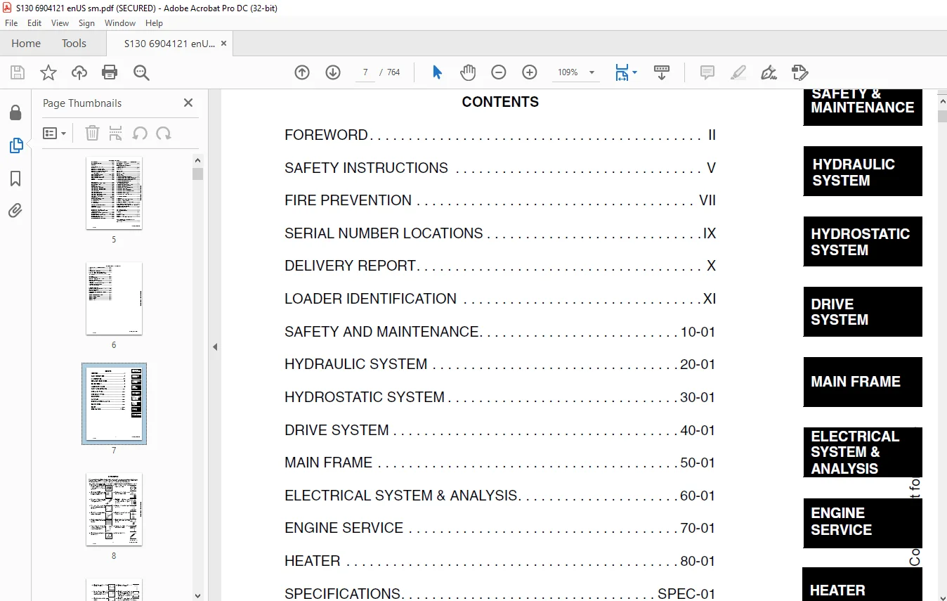
CONTENTS 7
FOREWORD 8
SAFETY INSTRUCTIONS 11
FIRE PREVENTION 13
Maintenance 13
Operation 13
Electrical 13
Hydraulic System 13
Fueling 13
Starting 13
Spark Arrestor Exhaust System 13
Welding And Grinding 14
Fire Extinguishers 14
SERIAL NUMBER LOCATIONS 15
Loader Serial Number 15
Engine Serial Number 15
DELIVERY REPORT 16
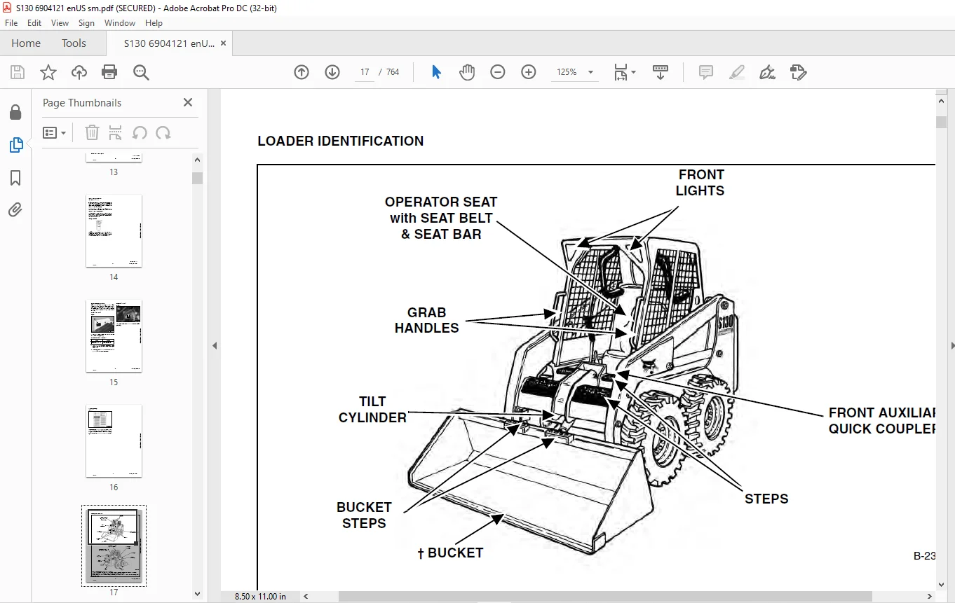
LOADER IDENTIFICATION 17
SAFETY AND MAINTENANCE 19
LIFTING AND BLOCKING THE LOADER 23
Procedure 23
LIFT ARM SUPPORT DEVICE 25
Installing 25
Removing 26
OPERATOR CAB 27
Description 27
Raising 28
Lowering 29
Cab Door Sensor 30
Special Applications Kit 30
Special Applications Kit Inspection And Maintenance 30
TRANSPORTING THE LOADER ON A TRAILER 31
Loading And Unloading 31
Fastening 31
TOWING THE LOADER 33
Procedure 33
REMOTE START TOOL KIT-MEL1563 35
Remote Start Tool – MEL1563 35
Service Tool Harness Control – MEL1565 36
Service Tool Harness Communicator – MEL1566 37
Remote Start Procedure 38
REMOTE START TOOL (SERVICE TOOL) KIT – 6689779 41
Description 41
Remote Start Tool (Service Tool) – 6689778 42
Loader Service Tool Harness – 6689747 43
Computer Service Tool Harness – 6689746 44
Remote Start Procedure 45
SERVICE SCHEDULE 49
Chart 49
AIR CLEANER SERVICE 51
Replacing Filter Elements 51
ENGINE COOLING SYSTEM 53
Cleaning 53
Checking Level 53
Removing And Replacing Coolant 54
FUEL SYSTEM 55
Fuel Specifications 55
Biodiesel Blend Fuel 55
Filling The Fuel Tank 56
Fuel Filter 57
Removing Air From The Fuel System 57
ENGINE LUBRICATION SYSTEM 59
Checking And Adding Engine Oil 59
Engine Oil Chart 59
Removing And Replacing Oil And Filter 60
HYDRAULIC / HYDROSTATIC SYSTEM 61
Checking And Adding Fluid 61
Hydraulic / Hydrostatic Fluid Chart 61
Removing And Replacing Hydraulic Fluid 62
Removing And Replacing Hydraulic / Hydrostatic Filter 63
Removing And Replacing Case Drain Filters 64
Removing And Replacing Hydraulic Charge Filter 65
Breather Cap 66
FINAL DRIVE TRANSMISSION (CHAINCASE) 67
Checking And Adding Oil 67
Removing And Replacing Oil 67
BOB-TACH (HAND LEVER) 69
Inspection And Maintenance 69
BOB-TACH (POWER) 71
Inspection And Maintenance 71
LUBRICATING THE LOADER 73
Lubrication Locations 73
TIRE MAINTENANCE 75
Wheel Nuts 75
Rotating 75
Mounting 76
SPARK ARRESTOR MUFFLER 77
Cleaning Procedure 77
PIVOT PINS 79
Inspection And Maintenance 79
LOADER STORAGE AND RETURN TO SERVICE 81
Storage 81
Return to Service 81
STOPPING THE ENGINE AND LEAVING THE LOADER 83
Procedure 83
Emergency Exit 84
HYDRAULIC SYSTEM 85
HYDRAULIC / HYDROSTATIC SCHEMATICS 89
HYDRAULIC SYSTEM INFORMATION 93
Glossary Of Hydraulic/Hydrostatic Symbols 93
Troubleshooting 97
CYLINDER (LIFT) 99
Testing 99
Removal And Installation 100
Parts Identification 101
Disassembly And Assembly 102
CYLINDER (TILT) 105
Testing 105
Removal And Installation 105
Rod End Pivot Pin Bushing And Seal Removal And Installation 107
Base End Pivot Pin Removal And Installation 107
Parts Identification 108
Disassembly And Assembly 109
CYLINDER (BOB-TACH) 113
Testing 113
Removal And Installation 114
Parts Identification 115
Disassembly and Assembly 116
MAIN RELIEF VALVE 119
Description 119
Testing 119
Adjusting 120
Removal and Installation 121
HYDRAULIC CONTROL VALVE (STANDARD) 123
Description 123
Removal And Installation 123
Identification Chart 128
Lift Load Check Valve Removal And Installation 129
Load Check Valve Removal And Installation (Tilt & Auxiliary) 130
Anti-Cavitation Valve Removal And Installation (Lift, Rod End) 130
Port Relief/Anti-Cavitation Valve Removal And Installation (Lift, Base End) 131
Port Relief/Anti-Cavitation Valve Removal And Installation (Tilt, Base End) 132
Port Relief/Anti-Cavitation Valve Removal And Installation (Tilt, Rod End) 132
Port Relief Valve Removal And Installation 133
Plug Removal And Installation 134
Rubber Boot Removal And Installation 135
End Cap/Spool Lock Block Removal And Installation 135
Lift Spool And Detent Removal And Installation 136
Tilt Spool Removal And Installation 146
Auxiliary Spool Removal And Installation 148
Auxiliary Solenoid Removal And Installation 150
Solenoid Removal And Installation 151
Lock Valve Removal And Installation 152
Lift Arm Bypass Orifice Removal And Installation 154
Main Relief Valve Removal And Installation 155
Check Valve Removal And Installation 156
HYDRAULIC CONTROL VALVE (ACS) OR (SJC) 157
Description 157
Removal And Installation 157
Actuator Removal And Installation (Out of Loader) 162
Identification Chart 165
Lift Load Check Valve Removal And Installation 166
Load Check Valve Removal And Installation (Tilt & Auxiliary) 167
Anti-Cavitation Valve Removal And Installation (Lift, Rod End) 168
Port Relief/Anti-Cavitation Valve Removal And Installation (Lift, Base End) 169
Port Relief/Anti-Cavitation Valve Removal And Installation (Tilt, Base End) 169
Port Relief/Anti-Cavitation Valve Removal And Installation (Tilt, Rod End) 170
Port Relief Valve Removal And Installation 170
Plug Removal And Installation 171
End Cap Block Removal And Installation 172
Lift Spool And Detent Removal And Installation 173
Tilt Spool Removal And Installation 178
Auxiliary Spool Removal And Installation 180
Auxiliary Solenoid Removal And Installation 181
Solenoid Removal And Installation 182
Lock Valve Removal And Installation 184
Lift Arm Bypass Orifice Removal And Installation 186
Main Relief Valve Removal And Installation 187
Check Valve Removal And Installation 188
LIFT ARM BYPASS CONTROL VALVE 189
Description 189
Testing 189
Removal and Installation 189
Disassembly And Assembly 190
HYDRAULIC PUMP (STANDARD) 191
Description 191
Pump Test At Quick Couplers 191
Direct Pump Test (Standard Section) 192
Direct Pump Test (Charge Section) 193
Removal And Installation 197
Hydraulic Pump Start Up 199
Parts Identification 200
Disassembly And Assembly 201
HYDRAULIC PUMP (SJC) 209
Description 209
Pump Test At Quick Couplers 209
Direct Pump Test (Standard Section) 210
Direct Pump Test (Charge Section) 212
Removal And Installation 214
Hydraulic Pump Start Up 214
Parts Identification 215
Disassembly And Assembly 216
HYDRAULIC/HYDROSTATIC FILTERS 217
Description 217
Housing Removal And Installation 217
Charge Filter Housing Removal And Installation 219
HYDRAULIC FLUID RESERVOIR 221
Description 221
Removal And Installation 221
Hydraulic Fluid Screen 222
OIL COOLER 223
Description 223
Removal and Installation 223
BUCKET POSITION VALVE 225
Description 225
Solenoid Removal And Installation 225
Solenoid Testing 226
Removal And Installation 226
Disassembly And Assembly 228
REAR AUXILIARY DIVERTER VALVE 231
Description 231
Solenoid Testing 231
Removal And Installation 231
Disassembly And Assembly 234
BOB-TACH (POWER) BLOCK 241
Description 241
Removal And Installation 241
Disassembly And Assembly 243
FRONT AUXILIARY HYDRAULIC COUPLER BLOCK 247
Description 247
Removal and Installation 247
Disassembly And Assembly 247
HYDROSTATIC SYSTEM 249
HYDROSTATIC SYSTEM INFORMATION 251
Troubleshooting 251
Description 252
HYDROSTATIC MOTOR 253
Description 253
Removal And Installation 253
Parts Identification 256
Disassembly And Assembly 257
HYDROSTATIC MOTOR CARRIER 263
Description 263
Shaft Seal Removal And Installation 263
Removal And Installation 265
Parts Identification 267
Disassembly and Assembly 268
HYDROSTATIC MOTOR CARRIER (SJC) 273
Description 273
Shaft Seal Removal And Installation 273
Removal And Installation 275
Parts Identification 277
Disassembly and Assembly 278
CHARGE PRESSURE 283
Description 283
Testing 283
Sender Removal And Installation 285
Adjusting 286
HYDROSTATIC PUMP 287
Description 287
Replenishing/High Pressure Relief Valve Removal And Installation 288
Removal And Installation 289
Hydrostatic Pump Start Up 290
Parts Identification (Left Half) 291
Parts Identification (Right Half) 292
Disassembly 293
Assembly 299
HYDROSTATIC PUMP (SJC) 307
Description 307
Hydraulic Controller Removal And Installation 308
Removal And Installation 310
Hydrostatic Pump Start Up 311
Parts Identification 312
High Pressure Relief and Bypass Valve 313
Charge Relief Valve 314
Disassembly And Assembly 315
Mechanical Neutral Adjustment 331
Hydraulic Controller Neutral Adjustment 334
DRIVE BELT 337
Description 337
Shield Removal And Installation 337
Adjusting 337
Belt Removal And Installation 339
Tensioner Pulley Removal And Installation 340
Tensioner Pulley Parts Identification 341
Tensioner Pulley Disassembly 342
Tensioner Pulley Assembly 343
CASE DRAIN FILTER 345
Description 345
Disassembly And Assembly 345
DRIVE SYSTEM 347
BRAKE 349
Description 349
Disk Removal And Installation 350
DRIVE COMPONENTS 351
Description 351
Axle Seal Removal And Installation 352
Axle Sprocket And Bearings Removal And Installation 354
Chain Removal And Installation 359
CHAINCASE 361
Description 361
Front Cover Removal And Installation 361
Center Cover Removal And Installation 362
Rear Cover Removal And Installation 363
MAIN FRAME 365
SEAT BAR 369
Description 369
Removal And Installation 369
Disassembly And Assembly 370
Compression Spring Disassembly And Assembly 372
OPERATOR CAB 373
Gas Cylinder Removal And Installation 373
Gas Cylinder Bracket Disassembly And Assembly 375
Removal And Installation 376
OPERATOR SEAT 379
Removal And Installation 379
Seat Belt Removal And Installation 379
OPERATOR SEAT (SUSPENSION) 381
Removal And Installation 381
Slide Rail Removal And Installation 382
Seat Belt Removal and Installation 382
Lower Cushion Removal And Installation 382
Back Cushion Removal And Installation 384
Shock Removal And Installation 384
3-Point Seat Belt Removal And Installation 385
BOB-TACH (HAND LEVER) 387
Description 387
Removal And Installation 387
Lever And Wedge Disassembly And Assembly 390
Bob-Tach Stops 391
Pivot Pin Bushing And Seal Removal And Installation 392
BOB-TACH (POWER – OPTION) 393
Description 393
Removal And Installation 393
Lever And Wedge Disassembly And Assembly 395
Bob-Tach Stops 396
Pivot Pin Bushing And Seal Removal And Installation 397
LIFT ARMS 399
Removal And Installation 399
REAR GRILL 405
Removal And Installation 405
REAR DOOR 407
Removal And Installation 407
Striker Removal and Installation 408
Striker Disassembly and Assembly 408
Striker (Adjusting) 408
Latch Removal And Installation 409
FUEL TANK 411
Removal And Installation 411
Fuel Level Sender Removal And Installation 412
Fuel Fill Screen Removal And Installation 412
CONTROL PEDALS AND LINKAGES 413
Description 413
Pedal Removal And Installation 413
Linkage Removal And Installation 414
Pedal (Adjusting) 416
CONTROL PEDALS (ACS) 417
Description 417
Foot Sensor Removal And Installation 417
Foot Pedal Removal And Installation 418
Foot Pedal Linkage Disassembly And Assembly 419
CONTROL PANEL 421
Description 421
Removal and Installation 422
Shock Removal And Installation 425
Shaft Removal And Installation 425
Shaft Disassembly And Assembly 426
Linkage Removal And Installation 427
Pintle Arm Disassembly and Assembly 431
Linkage Neutral Adjusting 433
Linkage Travel Adjusting 437
CONTROL PANEL (SJC) 441
Description 441
Removal And Installation 441
CONTROL HANDLE/LEVER 443
Description 443
Lever Removal And Installation 443
Boot Removal And Installation 443
CONTROL HANDLE/LEVER (ACS) 445
Description 445
Handle Sensor Removal And Installation 445
Handle Removal and Installation 448
Handle Disassembly and Assembly 449
Lever Removal and Installation 449
Boot Removal And Installation 451
CONTROL HANDLE/LEVER (SJC) (S/N 529214883 & Above, S/N 529611919 & Above) 453
Description 453
Joystick Testing 453
Joystick Removal And Installation 454
Removal And Installation 455
WINDOW (REAR) 457
Removal 457
Installation 457
WINDOW (TOP) 459
Removal And Installation 459
WINDOW (SIDE) 461
Removal And Installation 461
WINDOW (FRONT DOOR) 463
Removal (Standard Window) 463
Installation (Standard Window) 464
Removal And Installation (Special Applications Window) 466
ELECTRICAL SYSTEM & ANALYSIS 467
ELECTRICAL SCHEMATICS 471
ELECTRICAL SYSTEM INFORMATION 483
Glossary Of Electrical Symbols 483
Cab Harness Connectors 486
Mainframe Harness Connectors 487
Description 488
Troubleshooting 489
Fuse And Relay Location / Identification 490
Solenoid Testing 491
BATTERY 493
Removal And Installation 493
Servicing 494
Using A Booster Battery (Jump Starting) 495
ALTERNATOR 497
Belt Adjustment 497
Belt Replacement 497
Charging System Inspection 498
Alternator Voltage Testing 499
Low Voltage Testing 499
High Voltage Testing 500
Removal And Installation 501
Parts Identification 502
STARTER 503
Testing 503
Removal And Installation 504
Parts Identification 505
INSTRUMENT PANELS 507
Left Panel 507
Right Panel (Key Switch) 508
Right Panel (Keyless) 509
Side And Front Panels 511
Removal And Installation (Left And Right) 512
Bulb Removal And Installation (Left Only) 515
Key Switch Removal And Installation 516
Alarm Removal And Installation 517
Front Accessory Panel Removal And Installation 517
LIGHTS 519
Front Removal And Installation 519
Rear Removal And Installation 520
Cab Light Removal And Installation 520
BOBCAT CONTROLLER (MAIN) 521
Description 521
Connector Identification 522
Removal And Installation 524
BOBCAT CONTROLLER (ACS) 525
Description 525
Connector Identification 527
Removal and Installation 528
BOBCAT CONTROLLER (SJC) (DRIVE) 529
Description 529
Connector Identification 530
Removal and Installation 532
SPEED SENSORS (SJC) 533
Description 533
Testing 533
Removal And Installation 535
DIAGNOSTICS SERVICE CODES 537
Description 537
Service Codes List 538
BOBCAT INTERLOCK CONTROL SYSTEM (BICS) 543
Description 543
Inspecting The BICS Controller (Engine STOPPED – Key ON) 544
Inspecting Deactivation Of The Auxiliary Hydraulics System (Engine STOPPED – Key ON) 544
Inspecting The Seat Bar Sensor (Engine RUNNING) 544
Inspecting The Traction Lock (Engine RUNNING) 544
Inspecting The Lift Arm Bypass Control 544
Inspecting Deactivation Of Lift And Tilt Functions (ACS And SJC) 544
Troubleshooting 545
Troubleshooting Chart 546
SEAT BAR SENSOR 547
Description 547
Troubleshooting 547
Testing 548
Removal And Installation 549
Bobcat Interlock Control System (BICS) Circuit Test 551
TRACTION LOCK 553
Description 553
Troubleshooting 553
Removal And Installation 554
Inspecting 558
CONTROL SYSTEM (ACS) 559
Description 559
Troubleshooting Chart 560
Handle Sensor Connector Disassembly And Assembly 561
Switch Handle Removal 562
Switch Handle Installation 564
Actuator Connector Disassembly And Assembly 567
Handle Lock Solenoid Removal And Installation 568
Handle Lock Solenoid Disassembly And Assembly 568
Foot Sensor Disassembly And Assembly 569
Foot Lock Solenoid Removal And Installation 570
ELECTRICAL/HYDRAULIC CONTROLS 571
Identification Chart 571
ELECTRICAL/HYDRAULIC CONTROLS REFERENCE (SJC) 573
Identification Chart 573
SERVICE PC (LAPTOP COMPUTER) 577
Connecting To The Remote Start Tool 577
Connecting Remote Start Tool (Service Tool) 577
CALIBRATION 579
Description 579
Actuator Testing 579
Lift And Tilt Calibration (ACS) 581
Lift And Tilt Calibration (SJC) 583
Hydrostatic Pump Calibration (SJC) 585
STEERING DRIFT COMPENSATION 591
Description 591
Selecting And Adjusting 591
Exiting And Saving 592
FLYWHEEL RPM SENSOR 593
Description 593
Adjusting 593
CONTROL PANEL SETUP 595
Right Panel Setup (Keyless) 595
Attachment Control Information (Keyless) 596
PASSWORD SETUP (IF EQUIPPED WITH KEYLESS START) 597
Password Description 597
Changing The Owner And User Passwords 598
Password Lockout Feature 599
MAINTENANCE CLOCK 601
Description 601
Setup 602
Reset 606
BACK-UP ALARM SYSTEM 607
Description 607
Inspecting 607
Adjusting Switch Position 608
Troubleshooting (Standard and ACS) 609
Troubleshooting (Joystick) 610
Alarm Removal And Installation 611
Switch Removal And Installation 611
ENGINE SERVICE 613
ENGINE INFORMATION 615
Description 615
Specifications 616
Engine Torque Values 620
Troubleshooting 620
Engine Removal And Installation 622
Engine Mount Replacement 630
Compression – Checking 631
ENGINE SPEED CONTROL 633
Removal And Installation 633
ENGINE SPEED CONTROL (SJC) 635
Removal And Installation 635
Disassembly And Assembly 637
MUFFLER 639
Removal And Installation 639
AIR CLEANER 641
Housing Removal And Installation 641
ENGINE COOLING SYSTEM 643
Radiator Removal And Installation 643
Hydraulic Fan Description 645
Hydraulic Fan Disassembly And Assembly 645
Blower Housing Removal And Installation 646
Fan Removal And Installation 648
Hydraulic Fan Motor Removal And Installation 648
Water Pump Removal And Installation 649
Water Pump Disassembly And Assembly 649
Thermostat Housing Removal And Installation 650
LUBRICATION SYSTEM 651
Oil Pan Removal And Installation 651
Oil Pump Removal And Installation 651
Oil Pump Inspection 652
Engine Oil Pressure-Testing 653
FUEL SYSTEM 655
Fuel Camshaft Removal And Installation 655
Fuel Camshaft Governor Disassembly And Assembly 656
Fuel Shutoff Solenoid – Checking 657
Fuel Shutoff Solenoid Removal And Installation 657
Fuel Injection Pump Removal And Installation 658
Injection Pump – Timing 662
Fuel Injector Removal And Installation 664
Fuel Injector Nozzle Pressure – Checking 665
Nozzle Spray Condition 666
Valve Seat Tightness 666
CYLINDER HEAD 667
Glow Plugs – Testing 667
Glow Plugs Removal And Installation 667
Valve Clearance Adjustment 668
Valve Timing, Checking 669
Cylinder Head Removal And Installation 670
Cylinder Head Disassembly and Assembly 673
Cylinder Head – Servicing 673
Cylinder Head Top Clearance 674
Valve Guide-Checking 674
Reconditioning The Valve And Valve Seat 675
Valve Spring 677
Valve Tappets 678
Rocker Arm And Shaft Checking 678
CRANKSHAFT AND PISTONS 679
Piston And Connecting Rod Removal And Installation 679
Piston And Connecting Rod – Servicing 681
Cylinder Bore- Checking 683
Connecting Rod Alignment 684
Crankshaft And Bearings Removal And Installation 684
Crankshaft And Bearings – Servicing 686
CAMSHAFT AND TIMING GEARS 691
Timing Gearcase Cover Removal And Installation 691
Timing Gears Backlash – Checking 693
Idler Gear And Shaft Removal And Installation 694
Camshaft – Servicing 695
Idler Gear And Shaft Servicing 696
FLYWHEEL AND HOUSING 697
Flywheel Removal And Installation 697
Ring Gear Removal And Installation 697
Housing Removal And Installation 698
HEATER 701
HEATER SYSTEM 703
Description 703
REGULAR MAINTENANCE 705
Filter Elements Removal And Installation 705
Cleaning The Heater Coil 706
TROUBLESHOOTING 707
Blower Motor Does Not Operate 707
Blower Motor Operators Normally, But Air Flow Is Insufficient 707
Electrical System 708
Engine Coolant Bypassing The Heater Valve 712
Heater Valve Not Opening Or Closing 713
HEATER UNIT 715
Removal And Installation 715
HEATER COIL 717
Removal And Installation 717
HEATER FAN 719
Blower Removal And Installation 719
Disassembly And Assembly 720
Connector Identification 722
HEATER VALVE 723
Removal and Installation 723
Disassembly And Assembly 724
SPECIFICATIONS 725
(S130) LOADER SPECIFICATIONS 727
Machine Dimensions 727
Performance 728
Controls 728
Engine 728
Hydraulic System 729
Electrical 729
Drive System 730
Capacities 730
Tires 730
TORQUE SPECIFICATIONS FOR BOLTS 731
Torque For General SAE Bolts 731
Torque For General Metric Bolts 732
HYDRAULIC CONNECTION SPECIFICATIONS 733
O-ring Face Seal Connection 733
Straight Thread O-ring Fitting 734
Tubelines And Hoses 734
Flare Fitting 735
Port Seal Fitting 736
HYDRAULIC/HYDROSTATIC FLUID SPECIFICATIONS 737
Specifications 737
CONVERSIONS 739
Decimal And Millimeter Equivalent Chart 739
U S To Metric Conversion Chart 739
SERVICE MANUAL REVISION 741
Revision No: S130 – 1 741
Revision No: S130 – 2 743
Revision No: S130 – 3 745
Revision No: S130 – 4 747
Revision No: S130 – 5 749
Revision No: S130 – 6 751
Revision No: S130 – 7 753
Revision No: S130 – 8 755
Revision No: S130 – 9 757
Revision No: S130 – 10 759
Revision No: S130 – 11 761
Revision No: S130 – 12 763
IMAGES PREVIEW OF THE MANUAL:
Contact us: [email protected]
PLEASE NOTE:
- This is the same manual used by the dealers to diagnose and troubleshoot your vehicle
- You will be directed to the download page as soon as the purchase is completed. The whole payment and downloading process will take anywhere between 2-5 minutes
- Need any other service / repair / parts manual, please feel free to contact [email protected] . We still have 50,000 manuals unlisted
S.V