Bobcat S150, S160 Turbo Skid-Steer Loader Service Manual 6902730 (08-14) – PDF DOWNLOAD
$34.95
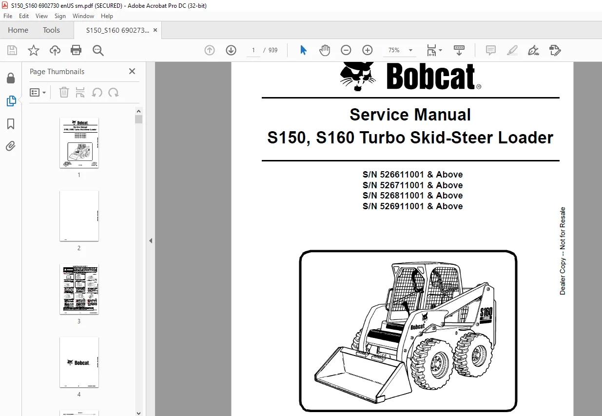
Bobcat S150 S160 Turbo Skid-Steer Loader Service Manual 6902730 (08-14) – PDF DOWNLOAD
S/N 526611001 & Above
S/N 526711001 & Above
S/N 526811001 & Above
S/N 526911001 & Above
Description
Bobcat S150, S160 Turbo Skid-Steer Loader Service Manual 6902730 (08-14) – PDF DOWNLOAD
FILE DETAILS:
Bobcat S150, S160 Turbo Skid-Steer Loader Service Manual 6902730 (08-14) – PDF DOWNLOAD
Language : English
Pages : 939
Downloadable : Yes
File Type : PDF
DESCRIPTION:
Bobcat S150, S160 Turbo Skid-Steer Loader Service Manual 6902730 (08-14) – PDF DOWNLOAD
S/N 526611001 & Above
S/N 526711001 & Above
S/N 526811001 & Above
S/N 526911001 & Above
FOREWORD:
This manual is for the Bobcat loader mechanic. It provides necessary servicing and adjustment procedures for the Bobcat loader and its component parts and systems. Refer to the Operation & Maintenance Manual for operating instructions, starting procedure, daily checks, etc.
A general inspection of the following items must be made after the loader has had service or repair:
TABLE OF CONTENTS:
Bobcat S150, S160 Turbo Skid-Steer Loader Service Manual 6902730 (08-14) – PDF DOWNLOAD
MAINTENANCE SAFETY 3
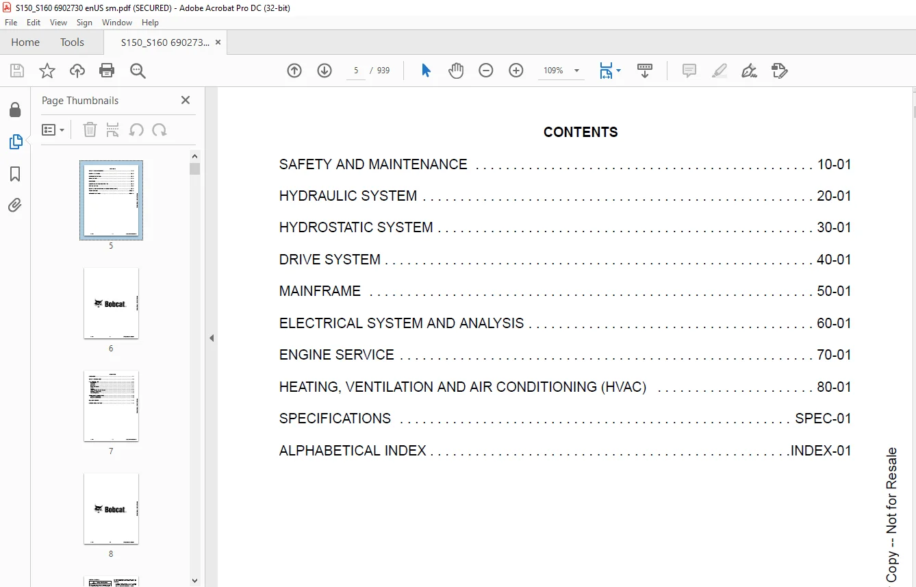
CONTENTS 5
FOREWORD 7
SAFETY INSTRUCTIONS 9
FIRE PREVENTION 11
Maintenance 11
Operation 11
Electrical 11
Hydraulic System 11
Fueling 11
Starting 11
Spark Arrester Exhaust System 11
Welding And Grinding 12
Fire Extinguishers 12
SERIAL NUMBER LOCATIONS 13
Loader Serial Number 13
Engine Serial Number 13
DELIVERY REPORT 14
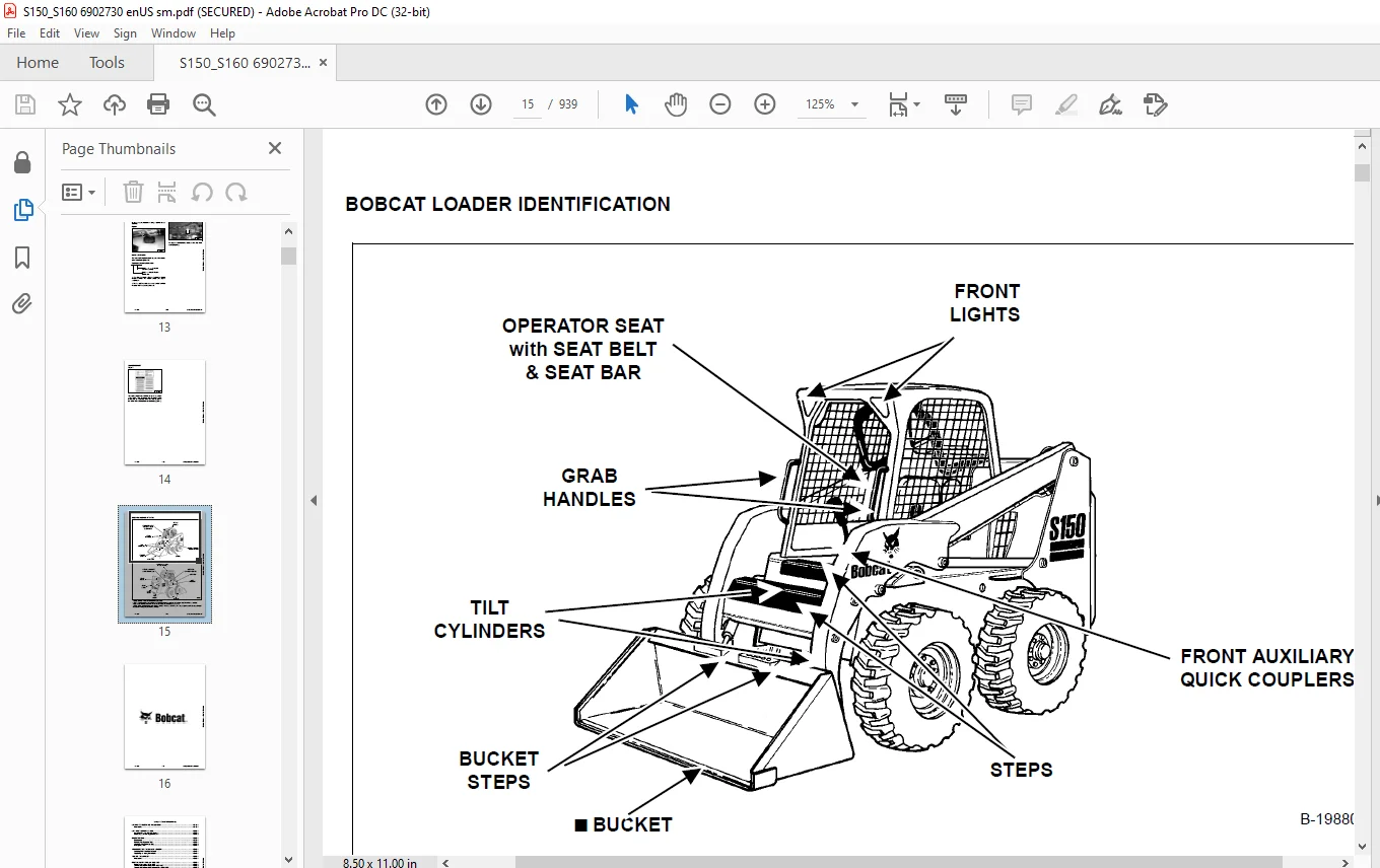
BOBCAT LOADER IDENTIFICATION 15
SAFETY AND MAINTENANCE 17
LIFTING AND BLOCKING THE LOADER 19
Procedure 19
LIFT ARM SUPPORT DEVICE 21
Installing Lift Arm Support Device 21
Removing Lift Arm Support Device 22
OPERATOR CAB 23
Description 23
Raising The Operator Cab 23
Lowering The Operator Cab 24
Emergency Exit 26
TRANSPORTING THE BOBCAT LOADER 27
Loading Onto Transport Vehicle 27
Fastening To Transport Vehicle 27
TOWING THE LOADER 29
Procedure 29
REMOTE START TOOL KIT -MEL1563 31
Remote Start Tool – MEL1563 31
Service Tool Harness Control – MEL1565 32
Service Tool Harness Communicator – MEL1566 33
Remote Start Procedure 34
REMOTE START TOOL (SERVICE TOOL) KIT – 7217666 37
Description 37
Remote Start Tool (Service Tool) – 7022042 38
Loader Service Tool Harness – 6689747 39
Computer Service Tool Harness – 6689746 40
Remote Start Procedure 41
SERVICE SCHEDULE 45
Chart 45
AIR CLEANER SERVICE 47
Testing 47
Replacing Filter Element(s) 47
ENGINE COOLING SYSTEM 49
Cleaning The Cooling System 49
Checking Coolant Level And Adding Coolant 49
Checking The Coolant Level 50
Replacing The Coolant 50
FUEL SYSTEM 53
Fuel Specifications 53
Filling The Fuel Tank 53
Fuel Filter 54
Removing Air From The Fuel System 55
ENGINE LUBRICATION SYSTEM 57
Checking Engine Oil 57
Engine Oil Chart 57
Replacing Oil And Filter 58
HYDRAULIC / HYDROSTATIC SYSTEM 59
Checking And Adding Fluid 59
Hydraulic / Hydrostatic Fluid Chart 59
Replacing Hydraulic / Hydrostatic Filter 59
Replacing Hydraulic Fluid 60
Breather Cap 61
FINAL DRIVE TRANSMISSION (CHAINCASE) 63
Checking And Adding Oil 63
Removing Oil From The Chaincase 63
FAN GEARBOX 65
Checking And Maintaining 65
BOB-TACH 67
Inspection And Maintenance 67
POWER BOB-TACH (OPTION) 69
Inspection And Maintenance 69
LUBRICATION OF THE BOBCAT LOADER 71
Procedure 71
TIRE MAINTENANCE 73
Wheel Nuts 73
Rotating 73
Mounting 73
SPARK ARRESTER MUFFLER 75
Cleaning Procedure 75
SEAT BELT 77
Inspection And Maintenance 77
HYDRAULIC SYSTEM 79
HYDRAULIC/HYDROSTATIC SCHEMATICS 85
HYDRAULIC SYSTEM INFORMATION 97
Tighten Procedures 101
Troubleshooting Chart 101
CYLINDER (LIFT) 103
Testing 103
Removal And Installation 104
Identification 105
Disassembly 106
Assembly 107
CYLINDER (TILT) 111
Testing 111
Removal And Installation 112
Base End Pivot Pin Replacement 113
Rod End Pivot Pin Bushing And Seal Replacement 114
Parts Identification 115
Disassembly 116
Assembly 117
CYLINDER (POWER BOB-TACH) 121
Testing 121
Removal And Installation 122
Identification 123
Disassembly 124
Assembly 125
MAIN RELIEF VALVE 129
Description 129
Testing 129
Adjustment 130
Removal And Installation 131
HYDRAULIC CONTROL VALVE (2 PIECE CASTING) (Foot control) 133
Identification 133
Removal And Installation 133
BICS™ Valve Removal And Installation 137
BICS™ Valve, Lift Arm Bypass Orifice Removal And Installation 138
BICS™ Valve, Check Valve Removal And Installation 140
BICS™ Valve Lock Valve Removal And Installation 141
BICS™ Valve Solenoid Removal And Installation 142
BICS™ Valve Solenoid Testing 143
Identification Chart 144
Load Check Valve 145
Main Relief Valve 146
Port Relief Valve 147
Anti-Cavitation Valve / Port Relief Valve 148
Anti-Cavitation Valve 148
Rubber Boot 149
Lift And Tilt Lock Block Removal And Installation 150
Lift Spool And Detent 150
Tilt Spool Removal And Installation 159
Auxiliary Spool Removal And Installation 161
Auxiliary Electric Solenoid 162
Port-Auxiliary Section 163
Cleaning And Inspection 164
HYDRAULIC CONTROL VALVE (2 PIECE CASTING) (ADVANCED CONTROL SYSTEM) (ACS) 165
Identification 165
Removal And Installation 165
BICS™ Valve Removal And Installation 169
BICS™ Valve, Lift Arm Bypass Orifice Removal And Installation 171
BICS™ Valve, Check Valve Removal And Installation 172
BICS™ Valve Lock Valve Removal And Installation 173
BICS™ Valve Solenoid Removal And Installation 174
BICS™ Valve Solenoid Testing 175
Actuator Removal And Installation 176
Identification Chart (ACS) 177
Lift Base End Restrictor 178
Load Check Valve 178
Main Relief Valve 179
Port Relief Valve 180
Anti-Cavitation Valve / Port Relief Valve 181
Anti-Cavitation Valve 182
Tilt Spool Removal And Installation 182
Lift Spool Removal And Installation 183
Lift and Tilt Spool Disassembly And Assembly 184
Auxiliary Spool Removal And Installation 185
Auxiliary Electric Solenoid 186
Port-Auxiliary Section 187
Cleaning And Inspection 187
HYDRAULIC CONTROL VALVE (1 PIECE CASTING) (FOOT CONTROL) 189
Identification 189
Removal And Installation 189
Identification Chart 194
Mount Bracket Removal And Installation 195
BICS™ Valve, Lift Load Check Valve Removal And Installation 195
Load Check Valve Removal And Installation (Tilt And Auxiliary) 196
Anti-Cavitation Valve (Lift, Rod End) 197
Port Relief / Anti-Cavitation Valve (Lift, Base End) 198
Port Relief / Anti-Cavitation Valve (Tilt, Base End) 198
Port Relief / Anti-Cavitation Valve (Tilt, Rod End) 199
Port Relief Valve 199
Plug Removal 200
Rubber Boot Removal And Installation 201
End Cap / Spool Lock Block Removal And Installation 202
Lift Spool And Detent Removal And Installation 203
Tilt Spool Removal And Installation 212
Auxiliary Spool Removal And Installation 214
Auxiliary Solenoid Disassembly And Assembly 216
BICS™ Valve Solenoid Disassembly And Assembly 217
BICS™ Valve, Lock Valve Removal And Installation 218
BICS™ Valve, Check Valve Removal And Installation 220
BICS™ Valve, Lift Arm Bypass Orifice Disassembly And Assembly 221
Main Relief Valve 221
HYDRAULIC CONTROL VALVE (1 PIECE CASTING) (ADVANCED CONTROL SYSTEM) (ACS) 223
Identification 223
Removal And Installation 223
Actuator Removal And Installation (Out Of Loader) 228
Identification Chart (ACS) 231
Mount Bracket Removal And Installation 232
BICS™ Valve, Lift Load Check Valve Removal And Installation 232
Load Check Valve Removal And Installation (Tilt And Auxiliary) 233
Anti-Cavitation Valve (Lift, Rod End) 234
Port Relief / Anti-Cavitation Valve (Lift, Base End) 235
Port Relief / Anti-Cavitation Valve (Tilt, Base End) 235
Port Relief / Anti-Cavitation Valve (Tilt, Rod End) 236
Port Relief Valve 236
Plug Removal 237
End Cap Block Removal And Installation 238
Lift Spool Removal And Installation 239
Tilt Spool Removal And Installation 243
Auxiliary Spool Removal And Installation 245
Auxiliary Solenoid Disassembly And Assembly 246
BICS™ Valve Solenoid Disassembly And Assembly 247
BICS™ Valve, Lock Valve Removal And Installation 248
BICS™ Valve, Check Valve Removal And Installation 250
BICS™ Valve, Lift Arm Bypass Orifice Disassembly And Assembly 251
Main Relief Valve 251
LIFT ARM BYPASS CONTROL VALVE 253
Inspecting 253
Removal And Installation 253
Disassembly And Assembly 254
HYDRAULIC PUMP 255
Check The Output Of The Hydraulic Pump Without Power Bob-Tach 255
Check The Output Of The Hydraulic Pump With Power Bob-Tach 257
Removal And Installation 259
Identification 261
Disassembly And Assembly 262
HYDRAULIC PUMP (HIGH FLOW) 267
Check The Output Of The Hydraulic Pump Without Power Bob-Tach 267
Check The Output Of The Hydraulic Pump With Power Bob-Tach 269
Removal And Installation 271
Identification 273
Disassembly And Assembly 274
HYDRAULIC PUMP (SJC) 283
Test The Output Of The Hydraulic Auxiliary Pump 283
Test The Output Of The Hydraulic Charge Pump 284
Removal And Installation 286
Identification 288
Disassembly And Assembly 289
HYDRAULIC PUMP (HIGH FLOW) (SJC) 297
Test The Output Of The Hydraulic Auxiliary Pump 297
Test The Output Of The Hydraulic Charge Pump 298
Test The Output Of The Hydraulic Pump (High Flow) 300
Removal And Installation 302
Identification 304
Disassembly And Assembly 305
HYDRAULIC / HYDROSTATIC FILTER HOUSING 317
Removal And Installation 317
HYDRAULIC FLUID RESERVOIR 319
Fluid Removal 319
Removal And Installation 319
BUCKET POSITION VALVE 323
Solenoid Removal And Installation 323
Solenoid Testing 323
Removal And Installation 324
Disassembly And Assembly 326
HIGH FLOW VALVE 329
Testing The High Flow Relief Valve 329
High Flow Relief Valve Adjustment Procedure 331
Removal And Installation 332
Disassembly And Assembly 334
Solenoid Testing 336
REAR AUXILIARY DIVERTER VALVE 337
Removal And Installation 337
Disassembly And Assembly 340
Solenoid Testing 345
Inspection 345
POWER BOB-TACH BLOCK 347
Removal And Installation 347
Disassembly And Assembly 349
FRONT AUXILIARY HYDRAULIC COUPLER BLOCK 353
Removal And Installation 353
Disassembly And Assembly 353
HYDROSTATIC SYSTEM 355
HYDROSTATIC SYSTEM INFORMATION 357
Troubleshooting Chart 357
Replenishing Valve Function 358
HYDROSTATIC MOTOR 359
Description 359
Removal And Installation 359
Parts Identification (Wet Bolt) 361
Disassembly (Wet Bolt) 362
Assembly (Wet Bolt) 367
Parts Identification (Dry Bolt) 373
Disassembly And Assembly (Dry Bolt) 374
HYDROSTATIC MOTOR CARRIER 379
Shaft Seal Replacement 379
Removal And Installation 381
Parts Identification 383
Disassembly And Assembly 384
HYDROSTATIC MOTOR CARRIER (SJC) 389
Shaft Seal Replacement 389
Removal And Installation 391
Parts Identification 393
Disassembly And Assembly 394
CHARGE PRESSURE 399
Sender Removal And Installation (Non SJC Machines) 399
Testing (Non SJC Machines) 399
Adjusting (Non SJC Machines) 400
Sender Removal And Installation (SJC Machines) 401
Testing (SJC Machines) 401
Adjusting (SJC Machines) 402
HYDROSTATIC PUMP 403
Replenishing / High Pressure Relief Valve 403
Removal And Installation 404
Parts Identification (Right Half) 406
Parts Identification (Left Half) 408
Hydraulic Pump Removal And Installation 410
Pump Separation 410
Disassembly 411
Assembly 417
HYDROSTATIC PUMP (SJC) 425
Description 425
Hydraulic Controller Removal And Installation 426
Removal And Installation 428
Parts Identification 430
High Pressure Relief And Bypass Valve 431
Charge Relief Valve 432
Disassembly And Assembly 433
Mechanical Neutral Adjustment 449
Hydraulic Controller Neutral Adjustment 452
DRIVE BELT 455
Shield Removal And Installation 455
Adjusting 455
Drive Belt Replacement 457
Tensioner Pulley Removal And Installation 458
Tensioner Pulley Parts Identification 459
Tensioner Pulley Disassembly 460
Tensioner Pulley Assembly 461
OIL COOLER 463
Removal And Installation 463
DRIVE SYSTEM 465
BRAKE 467
Disk Removal And Installation 467
Switch Operated Parking Brake 468
DRIVE COMPONENTS 469
Axle Seal Removal And Installation 469
Axle Sprocket And Bearings Removal And Installation 471
Chain Removal And Installation 476
CHAINCASE 479
Checking And Adding Oil 479
Removing The Oil 479
General Information 480
Front Cover Removal And Installation 480
Center Cover Removal And Installation 481
Rear Cover Removal And Installation 482
MAINFRAME 483
SEAT BAR 487
Removal And Installation 487
Assembling Components 488
Compression Spring Disassembly And Assembly 490
OPERATOR CAB 491
Gas Cylinder Removal And Installation 491
Gas Cylinder Disassembly 493
Removal And Installation 494
OPERATOR SEAT 497
Removal And Installation 497
Seat Belt Removal And Installation 497
OPERATOR SEAT (SUSPENSION) 499
Removal And Installation 499
Slide Rail Removal And Installation 500
Cushion Removal And Installation 500
Back Removal And Installation 501
Shock Removal And Installation 502
3-Point Seat Belt Removal And Installation 503
BOB-TACH 505
Removal And Installation 505
Bob-Tach Lever And Wedge 506
Pivot Pin Bushing And Seal Removal And Installation 507
POWER BOB-TACH 509
Removal And Installation 509
Power Bob-Tach Lever And Wedge 510
Pivot Pin Bushing And Seal Removal And Installation 512
LIFT ARMS 513
Removal And Installation 513
REAR GRILLE 517
Removal And Installation 517
REAR DOOR 519
Removal And Installation 519
Striker Removal And Installation 520
Striker Disassembly And Assembly 520
Adjusting The Striker 520
Latch Removal And Installation 521
FUEL TANK 523
Removal And Installation 523
Fuel Level Sender 524
Fuel Fill Screen 524
CONTROL PEDALS 527
Removal And Installation 527
Pedal Adjustment 527
Crossbar Linkage Removal And Installation 528
Lift Foot Pedal Linkage Removal And Installation 530
Tilt Foot Pedal Linkage Removal And Installation 530
CONTROL PEDALS (ACS) 531
Foot Sensor Removal And Installation 531
Foot Pedal Removal And Installation 532
Foot Pedal Linkage Disassembly And Assembly 533
CONTROL PANEL (NON-ADJUSTABLE PINTLES) 535
Removal And Installation 535
Shock Removal And Installation 538
Shaft Removal And Installation 538
Shaft Disassembly And Assembly 538
Linkage Removal And Installation 539
Linkage Adjustment 542
Linkage Neutral Adjustment 546
CONTROL PANEL (ADJUSTABLE PINTLES) 549
Description 549
Removal And Installation 550
Shock Removal And Installation 553
Shaft Removal And Installation 553
Shaft Disassembly And Assembly 554
Linkage Removal And Installation 555
Pintle Arm Disassembly And Assembly 559
Linkage Neutral Adjustment 561
Linkage Travel Adjustment 565
CONTROL PANEL (sjc) 569
Removal And Installation 569
CONTROL HANDLE 571
Control Lever Removal And Installation 571
Control Lever Boot 571
CONTROL HANDLE (ADVANCED CONTROL SYSTEM) (ACS) SELECTABLE HAND / FOOT CONTROL 573
Components Identification 573
Handle Sensor Removal And Installation 573
Control Handle Removal And Installation 576
Control Handle Disassembly And Assembly 577
Control Lever Removal And Installation 578
Control Lever Boot 579
CONTROL HANDLE (SJC) 581
Joystick Testing (Right And Left) 581
Joystick Removal And Installation (Right And Left) 582
Lever Assembly Removal (Right And Left) 583
ELECTRICAL SYSTEM AND ANALYSIS 585
ELECTRICAL SCHEMATICS 589
ELECTRICAL SYSTEM INFORMATION 598
Troubleshooting Chart 600
Description 601
Fuse Location 602
Relay Switch Location 602
BATTERY 604
Removal And Installation 604
Servicing 605
Using A Booster Battery (Jump Starting) 606
ALTERNATOR 608
Adjusting The Alternator Belt 608
Alternator Identification 608
Charging System Check 609
Alternator Voltage Test 610
Low Voltage Test 610
High Voltage Test 611
Removal And Installation 611
Rectifier Continuity (Diode) Test 613
Alternator Regulator Test 614
Disassembly 614
Stator Continuity Test 615
Stator Ground Test 615
Rotor Continuity Test 615
Rotor Ground Test 615
Assembly 616
STARTER 618
Checking 618
Removal And Installation 620
Parts Identification 621
Disassembly And Assembly 622
Inspection And Repair 625
No Load Test 627
INSTRUMENT PANEL 628
Left Panel 628
Right Panel (Standard) (With Key Switch) 629
Right Panel (Deluxe) (With Keyless Start) 630
Right Panel Setup Display Options (Deluxe) 632
Deluxe Panel Setup 633
Passwords (Deluxe) 633
Option And Field Accessory Panels (If Equipped) 635
Standard Panel Removal And Installation (Right Side) 636
Deluxe Panel Removal And Installation (Right Side) 637
Standard And Deluxe Panel Removal And Installation (Left Side) 638
Front Accessory Panel Removal And Installation 639
LIGHTS 640
Front Removal And Installation 640
Rear Removal And Installation 640
BOBCAT CONTROLLER 642
Identification Chart 642
Removal And Installation 644
CONTROLLER (SELECTABLE JOYSTICK CONTROL) (SJC) 646
Removal And Installation 646
Identification Chart 649
DIAGNOSTICS SERVICE CODES 652
Display 652
Number Codes List 653
BICS™ SYSTEM 660
Inspecting The BICS™ Controller (Engine STOPPED – Key ON) 660
Inspecting Deactivation Of The Auxiliary Hydraulics System (Engine STOPPED – Key ON) 660
Inspecting The Seat Bar Sensor (Engine RUNNING) 660
Inspecting The Traction Lock (Engine RUNNING) 660
Inspecting The Lift Arm Bypass Control 660
Troubleshooting Chart 661
Troubleshooting Guide 662
SEAT BAR SENSOR 664
Description 664
Troubleshooting 664
Testing 665
Removal And Installation 666
Bobcat Interlock Control System (BICS™) Circuit Test 669
TRACTION LOCK 672
Troubleshooting Chart 672
Description Of The Control System 673
Inspecting The Control System 673
Solenoid Removal And Installation 674
Guide Removal 676
Guide Installation 678
ADVANCED CONTROL SYSTEM (ACS) 680
Components Identification 680
Troubleshooting Guide 682
Controller, Connector And Wire Identification 683
ACS Controller Removal And Installation 684
Handle Sensor Connector 685
Switch Handle Removal 686
Switch Handle Installation 688
Actuators Disassembly And Assembly 691
Handle Lock Solenoid Removal And Installation 693
Handle Lock Solenoid Disassembly And Assembly 693
Handle Lock Solenoid Connector 694
Calibration Procedure 695
Foot Sensor Disassembly And Assembly 697
Foot Sensor Connector 697
Foot Lock Solenoid Removal And Installation 698
Foot Lock Solenoid Connector 699
ELECTRICAL / HYDRAULIC CONTROLS REFERENCE 700
Controls Identification Chart 700
ELECTRICAL / HYDRAULIC CONTROLS REFERENCE (selectable JOYstick control) (sjc) 702
Controls Identification Chart 702
FLYWHEEL RPM SENSOR 706
Adjustment 706
SERVICE PC (LAPTOP COMPUTER) 708
Connecting The Service PC To Remote Start Tool 708
Connecting Remote Start Tool (Service Tool) 708
CALIBRATION 710
Description 710
Actuator Testing 710
Lift And Tilt Calibration Procedure (SJC) 713
Hydrostatic Pump Calibration (SJC) 714
Calibration Procedure (ACS) 720
SPEED SENSOR 722
Description 722
Testing 722
Removal And Installation 724
ENGINE SERVICE 726
TROUBLESHOOTING 728
Chart 728
ENGINE SPEED CONTROL 730
Removal And Installation 730
Disassembly 731
MUFFLER 732
Removal And Installation 732
AIR CLEANER 734
Removal And Installation 734
RADIATOR 736
Removal And Installation 736
COOLING FAN 740
Drive Tension Pulley Removal And Installation 740
Gearbox / Blower Housing Removal And Installation 741
Blower Housing Grille Removal And Installation 743
Blower Disassembly And Assembly 744
Gearbox Parts Identification 746
Gearbox Disassembly 747
Gearbox Assembly 751
Gearbox Checking Backlash 756
ENGINE COMPONENTS AND TESTING 760
Compression Testing 760
Glow Plugs Testing 761
Glow Plugs Removal And Installation 761
Fuel Shut-Off Solenoid, Testing 762
Fuel Shut-Off Solenoid Removal And Installation 763
Fuel Injection Pump Removal And Installation (Turbo) 764
Fuel Injection Pump Removal And Installation (Non- Turbo) 767
Timing The Injection Pump 771
Fuel Injector Removal And Installation 773
Testing Nozzle Injection Pressure 774
Nozzle Spraying Condition 775
Valve Seat Tightness 775
Valve Clearance Adjustment 776
Valve Timing, Testing 777
ENGINE 778
Removal And Installation 778
Engine Mount Replacement 786
FLYWHEEL AND HOUSING 788
Flywheel Removal And Installation 788
Ring Gear Removal And Installation 788
Housing Removal And Installation 789
RECONDITIONING THE ENGINE-V2203-M-DI AND V2003-M-DI-T (TURBO) 792
Cylinder Head Removal And Installation 792
Cylinder Head Disassembly And Assembly 795
Cylinder Head Servicing 796
Cylinder Head Top Clearance 796
Valve Guide Checking 797
Reconditioning The Valve And Valve Seat 799
Valve Spring 800
Rocker Arm And Shaft Checking 801
Timing Gearcase Cover Removal And Installation 801
Idler Gear And Camshaft Removal And Installation 804
Camshaft Servicing 805
Idler Gear And Shaft Servicing 806
Timing Gears Checking Backlash 807
Fuel Camshaft Removal And Installation 807
Fuel Camshaft Governor 808
Crankshaft Gear Removal And Installation 808
Oil Pump Removal And Installation 809
Oil Pump Service 809
Checking Engine Oil Pressure 810
Valve Tappets 811
Piston And Connecting Rod Removal And Installation 811
Piston And Connecting Rod Servicing 813
Connecting Rod Alignment 816
Crankshaft And Bearings Removal And Installation 816
Crankshaft And Bearings, Servicing 818
Cylinder Bore, Checking 822
Water Pump Removal And Installation 823
Water Pump Disassembly And Assembly 823
TURBOCHARGER 824
Checking 824
Description 824
Removal And Installation 825
HEATING, VENTILATION AND AIR CONDITIONING (HVAC) 828
AIR CONDITIONING SYSTEM FLOW 831
Principals 831
Chart 832
COMPONENTS 834
Identification 834
SAFETY 838
Safety Equipment 838
REGULAR MAINTENANCE 840
Filter Elements Removal And Installation 840
Compressor Drive Belt Inspection 841
Cleaning The Condenser 842
BASIC TROUBLESHOOTING 844
Poor A/C Performance 844
Cleaning The A/C Evaporator Coil And Heater Coil 845
Compressor Drive Belt Inspection 846
Checking The Electrical System 847
Engine Coolant Bypassing The Heater Valve 855
Heater Valve Not Opening Or Closing 856
GENERAL AIR CONDITIONING SERVICE GUIDELINES 858
Compressor Oil 858
Compressor Oil Check 859
Component Replacement And Refrigeration Leaks 860
SYSTEM TROUBLESHOOTING CHART 862
Gauge Pressure Related Troubleshooting 863
TEMPERATURE / PRESSURE 866
Chart 866
AIR CONDITIONING SERVICE 868
Chart 868
SYSTEM CHARGING AND RECLAMATION 870
Reclamation Procedure 870
Charging Procedure With A Manifold Gauge Set 873
Charging Procedure 874
COMPRESSOR 876
Removal And Installation 876
Compressor Clutch Disassembly 877
CONDENSER 882
Removal And Installation 882
RECEIVER / DRIER 884
Removal And Installation 884
PRESSURE RELIEF VALVE 886
Removal And Installation 886
PRESSURE SWITCH 888
Removal And Installation 888
EVAPORATOR / HEATER UNIT 890
Removal And Installation 890
Disassembly And Assembly 892
THERMOSTAT 894
Removal And Installation 894
EXPANSION VALVE 896
Removal And Installation 896
EVAPORATOR 898
Removal And Installation 898
HEATER COIL 900
Removal And Installation With A/C 900
Removal And Installation Without A/C 901
HEATER / A/C FAN 904
Removal And Installation 904
Disassembly And Assembly 905
Wire Connector Removal And Installation 907
HEATER VALVE 910
Removal And Installation 910
Disassembly And Assembly 910
SPECIFICATIONS 912
LOADER SPECIFICATIONS 914
Machine Dimensions 914
Performance 915
Controls 915
Engine 915
Hydraulic System 916
Electrical 916
Drive System 917
Capacities 917
Tires 917
ENGINE SPECIFICATIONS-KUBOTA V2203-M-DI 918
Fuel Injection Nozzles 918
Fuel Injection Pump 918
Cylinder Head 918
Valves 918
Valve Springs 919
Valve Timing 919
Rocker Arms 919
Camshaft 919
Tappet 919
Cylinders 920
Piston Rings 920
Pistons 920
Connecting Rod 920
Oil Pump 920
Crankshaft 921
Timing Gear 921
Thermostat 921
ENGINE SPECIFICATIONS – KUBOTA V2003-M-DI-T (TURBO) 922
Fuel Injection Nozzles 922
Fuel Injection Pump 922
Cylinder Head 922
Valves 922
Valve Springs 923
Valve Timing 923
Rocker Arms 923
Camshaft 923
Tappet 923
Cylinder Liner 924
Piston Rings 924
Pistons 924
Connecting Rod 924
Oil Pump 924
Crankshaft 925
Timing Gear 925
Thermostat 925
TORQUE SPECIFICATIONS FOR BOLTS 926
Torque For General SAE Bolts 926
Torque For General Metric Bolts 927
HYDRAULIC CONNECTION SPECIFICATIONS 928
O-ring Face Seal Connection 928
Straight Thread O-ring Fitting 929
Tubelines And Hoses 929
Flare Fitting 929
O-ring Flare Fitting 930
Port Seal Fitting 932
HYDRAULIC / HYDROSTATIC FLUID SPECIFICATIONS 934
Specifications 934
CONVERSIONS 936
Decimal And Millimeter Equivalent Chart 936
U S To Metric Conversion Chart 936
ALPHABETICAL INDEX 938
IMAGES PREVIEW OF THE MANUAL:
Questions? Email us: [email protected]
PLEASE NOTE:
- This is the same manual used by the dealers to diagnose and troubleshoot your vehicle
- You will be directed to the download page as soon as the purchase is completed. The whole payment and downloading process will take anywhere between 2-5 minutes
- Need any other service / repair / parts manual, please feel free to contact [email protected] . We still have 50,000 manuals unlisted
S.V