Bobcat S175 & S185 Turbo High Flow Loader Service Manual 6901828 (11-08) – PDF DOWNLOAD
$32.95
Bobcat S175 & S185 Turbo High Flow Loader Service Manual 6901828 (11-08) – PDF DOWNLOAD
S/N 517625001 & Above
S/N 518115001 & Above
S/N 519028001 & Above
S/N 519215001 & Above
Description
Bobcat S175 & S185 Turbo High Flow Loader Service Manual 6901828 (11-08) – PDF DOWNLOAD
FILE DETAILS:
Bobcat S175 & S185 Turbo High Flow Loader Service Manual 6901828 (11-08) – PDF DOWNLOAD
Language : English
Pages : 725
Downloadable : Yes
File Type : PDF
DESCRIPTION:
Bobcat S175 & S185 Turbo High Flow Loader Service Manual 6901828 (11-08) – PDF DOWNLOAD
S/N 517625001 & Above
S/N 518115001 & Above
S/N 519028001 & Above
S/N 519215001 & Above
FOREWORD:
This manual is for the Bobcat loader mechanic. It provides necessary servicing and adjustment procedures for the Bobcat loader and its component parts and systems. Refer to the Operation & Maintenance Manual for operating instructions, starting procedure, daily checks, etc.
A general inspection of the following items must be made after the loader has had service or repair:
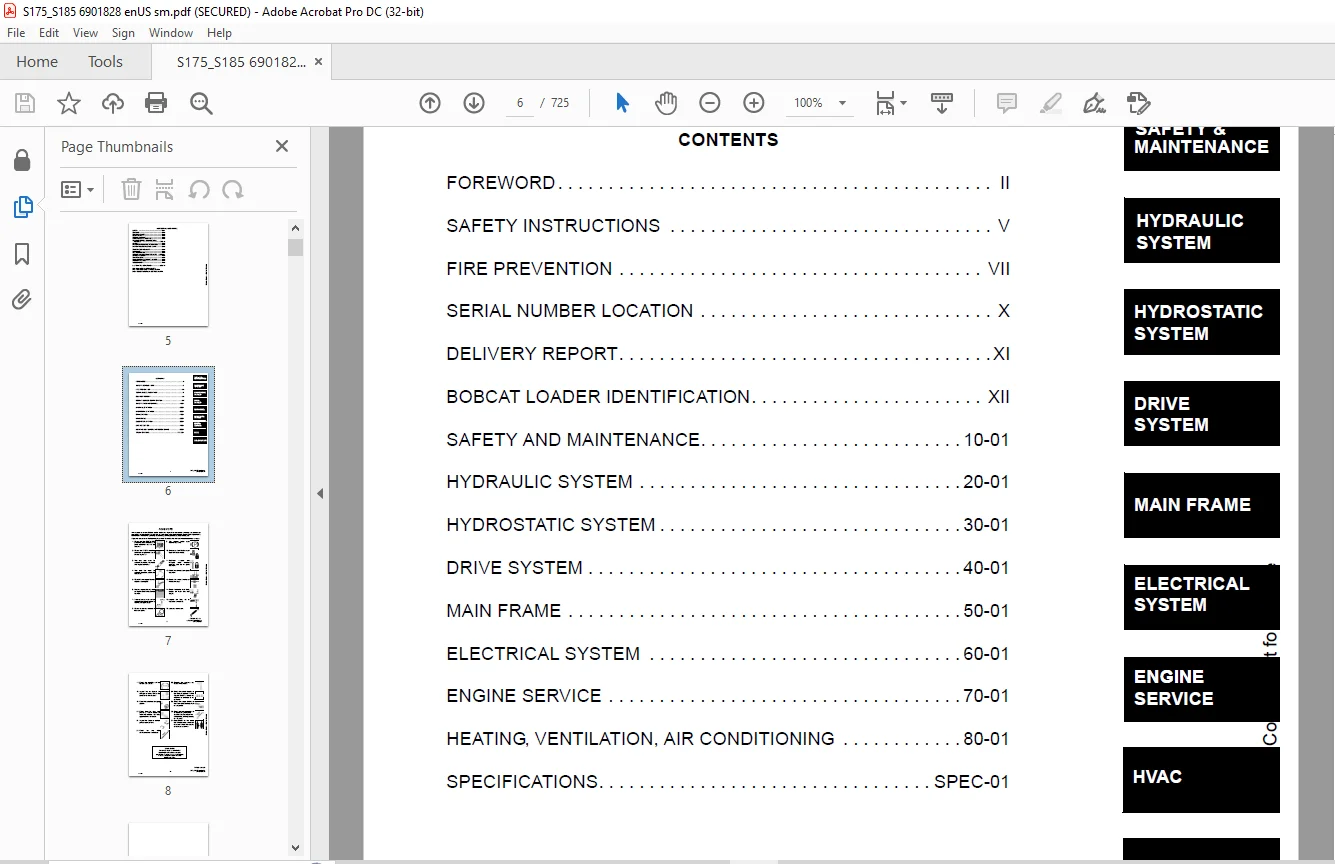
TABLE OF CONTENTS:
Bobcat S175 & S185 Turbo High Flow Loader Service Manual 6901828 (11-08) – PDF DOWNLOAD
MAINTENANCE SAFETY 2
ALPHABETICAL INDEX 4
CONTENTS 6
FOREWORD 7
SAFETY INSTRUCTIONS 10
FIRE PREVENTION 12
Maintenance 12
Operation 12
Electrical 12
Hydraulic System 12
Fueling 12
Starting 12
Spark Arrestor Exhaust System 12
Welding And Grinding 13
Fire Extinguishers 13
SERIAL NUMBER LOCATION 15
Loader Serial Number 15
Engine Serial Number 15
DELIVERY REPORT 16
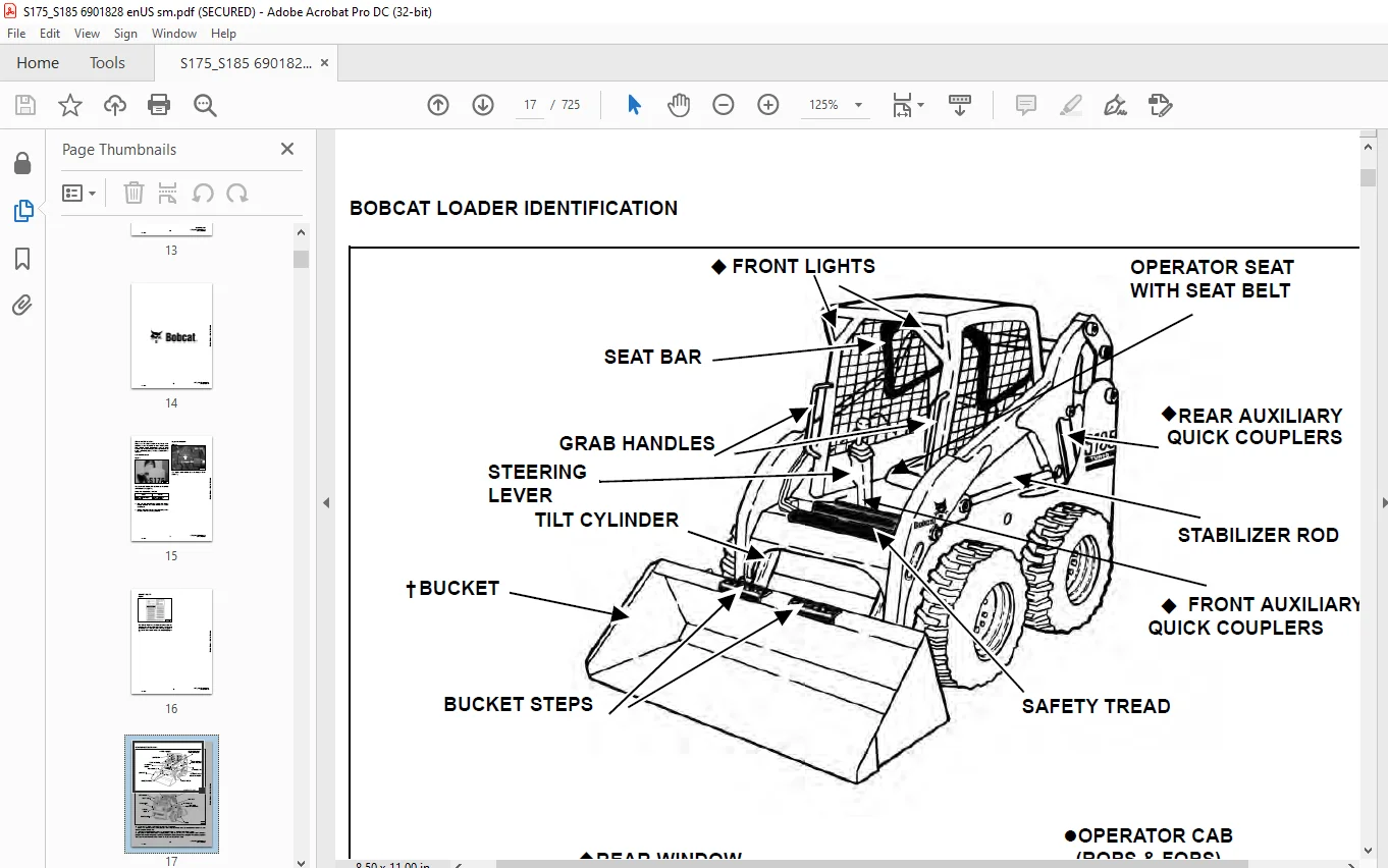
BOBCAT LOADER IDENTIFICATION 17
SAFETY AND MAINTENANCE 18
LIFTING AND BLOCKING THE LOADER 20
Procedure 20
LIFT ARM SUPPORT DEVICE 22
Installing Lift Arm Support Device 22
Removing Lift Arm Support Device 23
OPERATOR CAB 24
Description 24
Raising The Operator Cab 24
Lowering The Operator Cab 26
Emergency Exit 26
TRANSPORTING THE BOBCAT LOADER 30
Procedure 30
TOWING THE LOADER 32
Procedure 32
REMOTE START 34
Procedure 34
SERVICE SCHEDULE 36
Chart 36
AIR CLEANER SERVICE 38
Checking 38
Replacing Filter Element(s) 38
ENGINE COOLING SYSTEM 40
Cleaning The Cooling System 40
Checking The Coolant Level 40
Replacing the Coolant 41
KUBOTA V2203-EB 41
KUBOTA V2003T-EB (TURBO) 41
FUEL SYSTEM 44
Fuel Specifications 44
Filling The Fuel Tank 44
Fuel Filter 45
Removing Air From The Fuel System 45
ENGINE LUBRICATION SYSTEM 46
Checking Engine Oil 46
Oil Chart 46
Replacing Oil And Filter 46
HYDRAULIC/HYDROSTATIC SYSTEM 48
Checking And Adding Fluid 48
Replacing Hydraulic/Hydrostatic Filter 48
Replacing Hydraulic Fluid 48
Breather Cap 50
FINAL DRIVE TRANSMISSION (CHAINCASE) 52
Checking And Adding Oil 52
Removing Oil From The Chaincase 52
FAN GEARBOX 54
Checking And Maintaining 54
BOB-TACH 56
Inspection And Maintenance 56
POWER BOB-TACH (OPTION) 58
Inspection And Maintenance 58
LUBRICATION OF THE BOBCAT LOADER 60
Procedure 60
TIRE MAINTENANCE 64
Wheel Nuts 64
Rotating 64
Mounting 64
SPARK ARRESTOR MUFFLER 66
Cleaning Procedure 66
HYDRAULIC SYSTEM 68
HYDRAULIC / HYDROSTATIC SCHEMATICS 72
HYDRAULIC SYSTEM INFORMATION 76
Tighten Procedures 80
Troubleshooting Chart 80
CYLINDER (LIFT) 82
Checking 82
Removal And Installation 83
Identification 85
Disassembly 86
Assembly 87
CYLINDER (TILT) 90
Checking 90
Removal And Installation 91
Rod End Pivot Pin Bushing And Seal Replacement 92
Base End Pivot Pin Replacement 93
Identification 94
Disassembly 95
Assembly 96
CYLINDER (POWER BOB-TACH) 100
Checking 100
Removal And Installation 101
Identification 102
Disassembly 103
Assembly 104
MAIN RELIEF VALVE 108
Checking 108
Adjustment 109
Removal and Installation 109
HYDRAULIC CONTROL VALVE (FOOT CONTROL) 112
Removal And Installation 112
BICS™ Valve Removal And Installation 115
BICS™ Valve, Lift Arm By-Pass Orifice Removal And Installation 117
BICS™ Valve, Check Valve Removal And Installation 118
BICS™ Valve Lock Valve Removal And Installation 119
BICS™ Valve Solenoid Removal And Installation 120
BICS™ Valve Solenoid Testing 121
Identification Chart 122
Load Check Valve 123
Main Relief Valve 124
Port Relief Valve 125
Anti-Cavitation Valve/Port Relief Valve 126
Anti-Cavitation Valve 126
Rubber Boot 127
Lift And Tilt Lock Block Removal And Installation 128
Lift Spool and Detent 128
Tilt Spool Removal And Installation 137
Auxiliary Spool Removal And Installation 139
Auxiliary Electric Solenoid 140
Port-Auxiliary Section 141
Cleaning And Inspection 142
HYDRAULIC CONTROL VALVE (ADVANCED CONTROL SYSTEM) (ACS) 144
Description 144
Removal and Installation 144
BICS™ Valve Removal And Installation 148
BICS™ Valve, Lift Arm By-Pass Orifice Removal And Installation 150
BICS™ Valve, Check Valve Removal And Installation 150
BICS™ Valve Lock Valve Removal And Installation 152
BICS™ Valve Solenoid Removal And Installation 153
BICS™ Valve Solenoid Testing 154
Actuator Removal And Installation 155
Identification Chart (ACS) 156
Lift Base End Restrictor 157
Load Check Valve 157
Main Relief Valve 158
Port Relief Valve 159
Anti-Cavitation Valve/Port Relief Valve 160
Anti-Cavitation Valve 161
Tilt Spool Removal And Installation 161
Lift Spool Removal And Installation 162
Lift and Tilt Spool Disassembly And Assembly 163
Auxiliary Spool Removal And Installation 164
Auxiliary Electric Solenoid 165
Port-Auxiliary Section 166
Cleaning And Inspection 166
LIFT ARM BY-PASS CONTROL VALVE 168
Inspecting 168
Removal and Installation 168
Disassembly and Assembly 169
HYDRAULIC PUMP 170
Check The Output Of The Hydraulic Pump Without Power Bob-Tach 170
Check The Output Of The Hydraulic Pump With Power Bob-Tach 172
Removal And Installation 174
Identification 176
Disassembly And Assembly 177
HYDRAULIC PUMP (HI FLOW) 182
Check The Output Of The Hydraulic Pump Without Power Bob-Tach 182
Check The Output Of The Hydraulic Pump With Power Bob-Tach 184
Removal And Installation 186
Identification 188
Disassembly And Assembly 189
HYDRAULIC FILTER HOUSING 198
Removal and Installation 198
HYDRAULIC FLUID RESERVOIR 200
Fluid Removal 200
Removal And Installation 200
BUCKET POSITION VALVE 204
Solenoid Removal And Installation 204
Solenoid Testing 204
Removal and Installation 205
Disassembly And Assembly 207
SELECT VALVE 210
Checking The High Flow Pump Relief Valve 210
Removal and Installation 212
Disassembly And Assembly 215
Solenoid Testing 220
REAR AUXILIARY DIVERTER VALVE (DUAL SHUTTLE) 222
Removal And Installation 222
Disassembly And Assembly 225
Solenoid Testing 228
Inspection 228
POWER BOB-TACH BLOCK 230
Removal And Installation 230
Disassembly And Assembly 231
FRONT AUXILARY HYDRAULIC COUPLER BLOCK 240
Removal and Installation 240
Disassembly And Assembly 240
HYDROSTATIC SYSTEM 242
HYDROSTATIC SYSTEM INFORMATION 244
Troubleshooting Chart 244
Replenishing Valve Function 245
HYDROSTATIC MOTOR 246
Removal And Installation 246
Parts Identification 248
Disassembly 249
Assembly 254
Carrier Shaft Seal Replacement 260
Carrier Parts Identification 264
Carrier Disassembly 265
Carrier Assembly 266
CHARGE PRESSURE 270
Sender Removal And Installation 270
Checking Charge Pressure 270
Adjusting 271
HYDROSTATIC PUMP 272
Replenishing/High Pressure Relief Valve 272
Removal And Installation 272
Parts Identification (Right Half) 275
Parts Identification (Left Half) 277
Hydraulic Pump Removal And Installation 279
Pump Separation 279
Disassembly 280
Assembly 286
DRIVE BELT 294
Shield Removal And Installation 294
Adjusting 294
Drive Belt Replacement 296
Tensioner Pulley Removal And Installation 296
Tensioner Pulley Parts Indentification 298
Tensioner Pulley Disassembly 299
Tensioner Pulley Assembly 300
OIL COOLER 302
Removal and Installation 302
DRIVE SYSTEM 304
BRAKE 306
Disk Removal And Installation 306
Switch Operated Parking Brake 307
DRIVE COMPONENTS 308
Axle Seal Removal And Installation 308
Axle Sprocket And Bearings Removal And Installation 310
Chain Removal And Installation 315
CHAINCASE 318
Checking And Adding Oil 318
Removing The Oil 318
Front Cover Removal And Installation 319
Center Cover Removal And Installation 320
Rear Cover Removal And Installation 321
MAIN FRAME 322
SEAT BAR 324
Removal And Installation 324
Assembling Components 325
Compression Spring Disassembly And Assembly 327
OPERATOR CAB 328
Gas Cylinder Removal And Installation 328
Gas Cylinder Disassembly 330
Removal And Installation 330
OPERATOR SEAT 334
Removal And Installation 334
Seat Belt Removal And Installation 334
OPERATOR SEAT (SUSPENSION) 336
Removal And Installation 336
Slide Rail Removal And Installation 337
Cushion Removal And Installation 337
Back Removal And Installation 338
Shock Removal And Installation 339
BOB-TACH 340
Removal And Installation 340
Bob-Tach Lever And Wedge 341
Pivot Pin Bushing And Seal Replacement 342
POWER BOB-TACH 344
Removal And Installation 344
Power Bob-Tach Lever And Wedge 345
Pivot Pin Bushing And Seal Replacement 347
LIFT ARM 348
Removal And Installation 348
Link Removal And Installation 351
Stabilizer Bar Removal And Installation 353
REAR GRILL 354
Gas Cylinder Removal And Installation 354
Removal And Installation 354
REAR DOOR 356
Removal And Installation 356
Striker Removal and Installation 357
Striker Disassembly and Assembly 357
Adjusting The Striker 357
Latch Removal and Installation 358
FUEL TANK 360
Removal And Installation 360
Fuel Level Sender 361
Fuel Fill Screen 361
CONTROL PEDALS 364
Removal And Installation 364
Pedal Adjustment 364
Crossbar Linkage Removal and Installation 365
Lift Foot Pedal Linkage Removal and Installation 366
Tilt Foot Pedal Linkage Removal and Installation 366
CONTROL PEDALS (ACS) 368
Foot Sensor Removal And Installation 368
Foot Pedal Removal And Installation 369
Foot Pedal Linkage Disassembly And Assembly 370
CONTROL PANEL 372
Removal and Installation 372
Shock Removal And Installation 374
Shaft Removal And Installation 374
Shaft Disassembly And Assembly 374
Linkage Removal And Installation 375
Linkage Adjustment 378
Linkage Neutral Adjustment 381
CONTROL HANDLE 384
Control Lever Removal And Installation 384
Control Lever Boot 384
CONTROL HANDLE (ADVANCED CONTROL SYSTEM) (ACS) ADVANCED HAND CONTROL 386
Components Identification 386
Handle Sensor Removal And Installation 387
Control Handle Removal and Installation 389
Control Handle Disassembly and Assembly 390
Control Lever Removal and Installation 391
Control Lever Boot 392
CONTROL HANDLE (ADVANCED CONTROL SYSTEM) (ACS) SELECTABLE HAND/FOOT CONTROL 394
Components Identification 394
Handle Sensor Removal And Installation 395
Control Handle Removal and Installation 398
Control Handle Disassembly and Assembly 399
Control Lever Removal and Installation 399
Control Lever Boot 400
ELECTRICAL SYSTEM 402
ELECTRICAL SCHEMATICS 406
ELECTRICAL SYSTEM INFORMATION 412
Troubleshooting Chart 414
Description 415
Fuse Location 416
Relay Switch Location 416
BATTERY 418
Removal And Installation 418
Servicing 419
Using A Booster Battery (Jump Starting) 420
ALTERNATOR (90 AMP) 422
Adjusting The Alternator Belt 422
Alternator Identification 422
Charging System Check 423
Alternator Voltage Test 424
Low Voltage Test 425
High Voltage Test 425
Removal And Installation 425
Rectifier Continuity (Diode) Test 426
Alternator Regulator Test 427
Disassembly 428
Stator Continuity Test 429
Stator Ground Test 429
Rotor Continuity Test 429
Rotor Ground Test 429
Assembly 430
STARTER 432
Checking 432
Removal And Installation 433
Parts Identification 434
Disassembly and Assembly 435
Inspection And Repair 438
No Load Test 440
INSTRUMENT PANEL 442
Left Panel 442
Right Panel (Standard) (With Key Switch) 443
Right Panel – (Deluxe) (With Keyless Start) 444
Option and Field Accessory Panels 449
Removal And Installation 450
Front Accessory Panel Removal And Installation 451
LIGHTS 452
Front Removal And Installation 452
Rear Removal And Installation 452
BOBCAT CONTROLLER 454
Identification Chart (S/N 517625419 & Below, S/N 519029062 & Below) 454
Identification Chart (S/N 517625420 & Above, S/N 519029063 & Above) 455
Removal And Installation 457
DIAGNOSTICS 460
Service Codes 460
BICS™ SYSTEM 464
Inspecting The BICS™ Controller (Engine STOPPED – Key ON) 464
Inspecting Deactivation Of The Auxiliary Hydraulics System (Engine STOPPED – Key ON) 464
Inspecting The Seat Bar Sensor (Engine RUNNING) 464
Inspecting The Traction Lock (Engine RUNNING) 464
Inspecting The Lift Arm By-Pass Control 464
Additional Inspection For Loaders With Advanced Hand Controls (ACS) 465
Troubleshooting Chart 466
Troubleshooting Guide 467
SEAT BAR SENSOR 468
Troubleshooting Chart 468
Test 469
Removal And Installation 470
BICS™ Circuit Test 471
TRACTION LOCK 472
Troubleshooting Chart 472
Inspecting 473
Solenoid Removal And Installation 473
Guide Removal 476
Guide Installation 477
ADVANCED CONTROL SYSTEM (ACS) ADVANCED HAND CONTROL 480
Components Identification 480
Troubleshooting Guide 481
Controller, Connector And Wire Identification 482
ACS Controller Removal And Installation 483
Handle Sensor Connector 484
Switch Handle Removal 485
Switch Handle Installation 487
Actuators Disassembly and Assembly 490
ADVANCED CONTROL SYSTEM (ACS) SELECTABLE HAND/FOOT CONTROL 492
Components Identification 492
Troubleshooting Guide 494
Controller, Connector And Wire Identification 495
ACS Controller Removal And Installation 496
Handle Sensor Connector 497
Switch Handle Removal 498
Switch Handle Installation 500
Actuators Disassembly and Assembly 503
Handle Lock Solenoid Removal And Installation 505
Handle Lock Solenoid Disassembly And Assembly 505
Handle Lock Solenoid Connector 506
Calibration Of The ACS System 507
Switchable Hand/Foot Controls Calibration Procedure 507
Hand Controls Only Calibration Procedure 508
Foot Sensor Disassembly And Assembly 510
Foot Sensor Connector 510
Foot Lock Solenoid Removal And Installation 511
Foot Lock Solenoid Connector 512
ELECTRICAL/HYDRAULIC CONTROLS REFERENCE 514
Controls Identification Chart 514
ENGINE SERVICE 516
TROUBLESHOOTING 518
Chart 518
ENGINE SPEED CONTROL 520
Removal And Installation 520
Disassembly 520
MUFFLER 522
Removal And Installation 522
AIR CLEANER 524
Removal And Installation 524
RADIATOR 526
Removal And Installation 526
COOLING FAN 528
Drive Tension Pulley Removal And Installation 528
Gearbox/Blower Housing Removal And Installation 529
Blower Housing Grill Removal And Installation 531
Blower Disassembly And Assembly 531
Gearbox Parts Identification 533
Gearbox Disassembly 534
Gearbox Assembly 538
Gearbox Checking Backlash 543
ENGINE COMPONENTS AND TESTING 546
Compression Checking 546
Glow Plugs Checking 547
Glow Plugs Removal And Installation 547
Fuel Shut-Off Solenoid, Checking 548
Fuel Shut-Off Solenoid, Adjusting 548
Fuel Shut-Off Solenoid Removal And Installation 549
Checking 550
Fuel Injection Pump Removal And Installation 550
Timing The Injection Pump 553
Fuel Injector Removal And Installation 555
Fuel Injector Checking 557
Fuel Injector Disassembly 557
Fuel Injector Assembly 558
Valve Clearance Adjustment 558
Rocker Arm And Shaft Checking 559
Valve Timing, Checking 559
ENGINE 560
Removal And Installation 560
Engine Mount Replacement 568
FLYWHEEL AND HOUSING 570
Flywheel Removal And Installation 570
Ring Gear Removal And Installation 571
Housing Removal And Installation 571
RPM SENSOR 574
Adjustment 574
RECONDITIONING THE ENGINE-KUBOTA V2203-EB AND V2003T-EB (TURBO) 576
Cylinder Head Removal And Installation 576
Cylinder Head Disassembly And Assembly 577
Cylinder Head Servicing 578
Cylinder Head Top Clearance 578
Checking The Valve Guide 579
Reconditioning The Valve And Valve Seat 580
Valve Spring 581
Rocker Arm And Shaft Checking 582
Timing Gearcase Cover Removal And Installation 582
Idler Gear And Camshaft Removal And Installation 584
Servicing The Camshaft 585
Servicing The Idle Gear And Shaft 587
Timing Gears Checking Backlash 588
Fuel Camshaft Removal And Installation 588
Fuel Camshaft Governor 589
Crankshaft Gear Removal And Installation 589
Oil Pump Removal And Installation 590
Oil Pump Service 590
Checking Engine Oil Pressure 592
Relief Valve 592
Piston And Connecting Rod Removal And Installation 593
Servicing The Piston And Connecting Rod 594
Servicing The Piston And Connecting Rod (Cont’d) 595
Connecting Rod Alignment 596
Crankshaft And Bearings Removal And Installation 597
Servicing The Crankshaft And Bearings 598
Checking The Cylinder Bore 601
Water Pump Disassembly And Assembly 602
TURBOCHARGER 604
Troubleshooting 604
Description 605
Removal and Installation 605
HEATING, VENTILATION, AIR CONDITIONING 608
AIR CONDITIONING SYSTEM FLOW 611
Principals 611
Chart 612
COMPONENTS 614
Identification 614
SAFETY 618
Safety Equipment 618
REGULAR MAINTENANCE 620
Filter Elements Removal And Installation 620
Compressor Drive Belt Inspection 621
Cleaning The Condenser 622
BASIC TROUBLESHOOTING 624
Poor A/C Performance 624
Cleaning The A/C Evaporator Coil & Heater Coil 624
Compressor Drive Belt Inspection: 627
Checking The Electrical System 627
Engine Coolant By-Passing The Heater Valve 635
Heater Valve Not Opening Or Closing 636
GENERAL AIR CONDITIONING SERVICE GUIDELINES 638
Compressor Oil 638
Compressor Oil Check 639
Component Replacement And Refrigeration Leaks 640
SYSTEM TROUBLESHOOTING CHART 642
Gauge Pressure Related Troubleshooting 643
TEMPERATURE/PRESSURE 646
Chart 646
AIR CONDITIONING SERVICE 648
Chart 648
SYSTEM CHARGING AND RECLAMATION 650
Reclamation Procedure 650
Charging Procedure With A Manifold Gauge Set 653
Charging Procedure 654
COMPRESSOR 656
Removal And Installation 656
Compressor Clutch Disassembly 657
CONDENSER 662
Removal And Installation 662
RECEIVER/DRIER 664
Removal And Installation 664
PRESSURE RELIEF VALVE 666
Removal And Installation 666
PRESSURE SWITCH 668
Removal And Installation 668
EVAPORATOR/HEATER UNIT 670
Removal And Installation 670
Disassembly And Assembly 672
THERMOSTAT 674
Removal And Installation 674
EXPANSION VALVE 676
Removal And Installation 676
EVAPORATOR 678
Removal And Installation 678
HEATER COIL 680
Removal And Installation With A/C 680
Removal And Installation Without A/C 681
HEATER/AC FAN 682
Removal And Installation 682
Disassembly And Assembly 683
Wire Connector Removal and Installation 685
HEATER VALVE 688
Removal And Installation 688
Disassembly And Assembly 688
SPECIFICATIONS 690
LOADER SPECIFICATIONS 692
Machine Dimensions 692
Performance 693
Controls 693
Engine 693
Hydraulic System 694
Electrical 694
Drive System 695
Capacities 695
Tires 695
ENGINE SPECIFICATIONS – KUBOTA V2203-EB 696
Fuel Injection Nozzles 696
Fuel Injection Pump 696
Cylinder Head 696
Valves 696
Valve Springs 697
Valve Timing 697
Rocker Arms 697
Camshaft 697
Tappet 697
Cylinders 698
Piston Rings 698
Pistons 698
Connecting Rod 698
Oil Pump 698
Crankshaft 699
Timing Gear 699
Thermostat 699
Crankshaft Re-Grind Data 700
ENGINE SPECIFICATIONS – KUOBTA V2003T-EB (TURBO) 702
Fuel Injection Nozzles 702
Fuel Injection Pump 702
Cylinder Head 702
Valves 702
Valve Springs 703
Valve Timing 703
Rocker Arms 703
Camshaft 703
Tappet 703
Cylinder Liner 704
Piston Rings 704
Pistons 704
Connecting Rod 704
Oil Pump 704
Crankshaft 705
Timing Gear 705
Thermostat 705
Crankshaft Re-Grind Data 706
TORQUE SPECIFICATIONS FOR BOLTS 708
Torque For General SAE Bolts 708
Torque For General Metric Bolts 709
HYDRAULIC CONNECTION SPECIFICATIONS 710
O-ring Face Seal Connection 710
Straight Thread O-ring Fitting 711
Tubelines And Hoses 711
Flare Fitting 711
O-ring Flare Fitting 712
Port Seal Fitting 714
HYDRAULIC FLUID SPECIFICATIONS 716
Specifications 716
CONVERSIONS 718
Decimal And Millimeter Equivalents 718
U S To Metric Conversion 718
SMR 720
S175, S185-1 720
S175, S185-2 722
S175, S185-3 724
IMAGES PREVIEW OF THE MANUAL:
Contact us: [email protected]
PLEASE NOTE:
- This is the SAME manual used by the dealers to troubleshoot any faults in your vehicle. This can be yours in 2 minutes after the payment is made.
- Contact us at [email protected] should you have any queries before your purchase or that you need any other service / repair / parts operators manual.
S.V