Bobcat S175 & S185 Turbo High Flow Loader Service Manual 6902732 (7-09) – PDF DOWNLOAD
$34.95
Bobcat S175 & S185 Turbo High Flow Loader Service Manual 6902732 (7-09) – PDF DOWNLOAD
S/N 525011001 & Above
S/N 525111001 & Above
S/N 525211001 & Above
S/N 525311001 & Above
Description
Bobcat S175 & S185 Turbo High Flow Loader Service Manual 6902732 (7-09) – PDF DOWNLOAD
FILE DETAILS:
Bobcat S175 & S185 Turbo High Flow Loader Service Manual 6902732 (7-09) – PDF DOWNLOAD
Language : English
Pages : 943
Downloadable : Yes
File Type : PDF
DESCRIPTION:
Bobcat S175 & S185 Turbo High Flow Loader Service Manual 6902732 (7-09) – PDF DOWNLOAD
S/N 525011001 & Above
S/N 525111001 & Above
S/N 525211001 & Above
S/N 525311001 & Above
FOREWORD:
This manual is for the Bobcat loader mechanic. It provides necessary servicing and adjustment procedures for the Bobcat loader and its component parts and systems. Refer to the Operation & Maintenance Manual for operating instructions, starting procedure, daily checks, etc.
A general inspection of the following items must be made after the loader has had service or repair:
TABLE OF CONTENTS:
Bobcat S175 & S185 Turbo High Flow Loader Service Manual 6902732 (7-09) – PDF DOWNLOAD
MAINTENANCE SAFETY 3
ALPHABETICAL INDEX 5
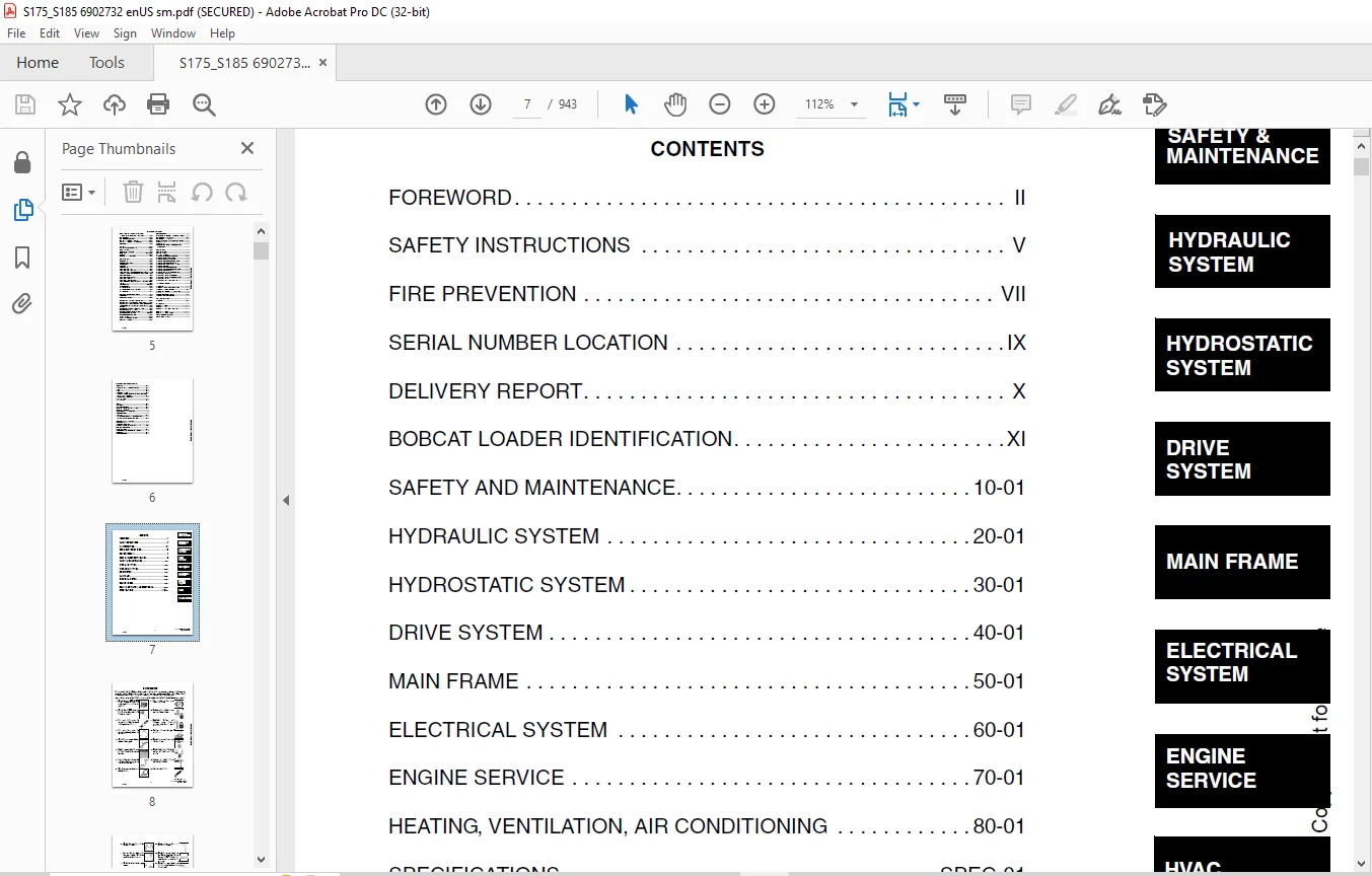
CONTENTS 7
FOREWORD 8
SAFETY INSTRUCTIONS 11
FIRE PREVENTION 13
Maintenance 13
Operation 13
Electrical 13
Hydraulic System 13
Fueling 13
Starting 13
Spark Arrestor Exhaust System 13
Welding And Grinding 14
Fire Extinguishers 14
SERIAL NUMBER LOCATION 15
Loader Serial Number 15
Engine Serial Number 15
DELIVERY REPORT 16
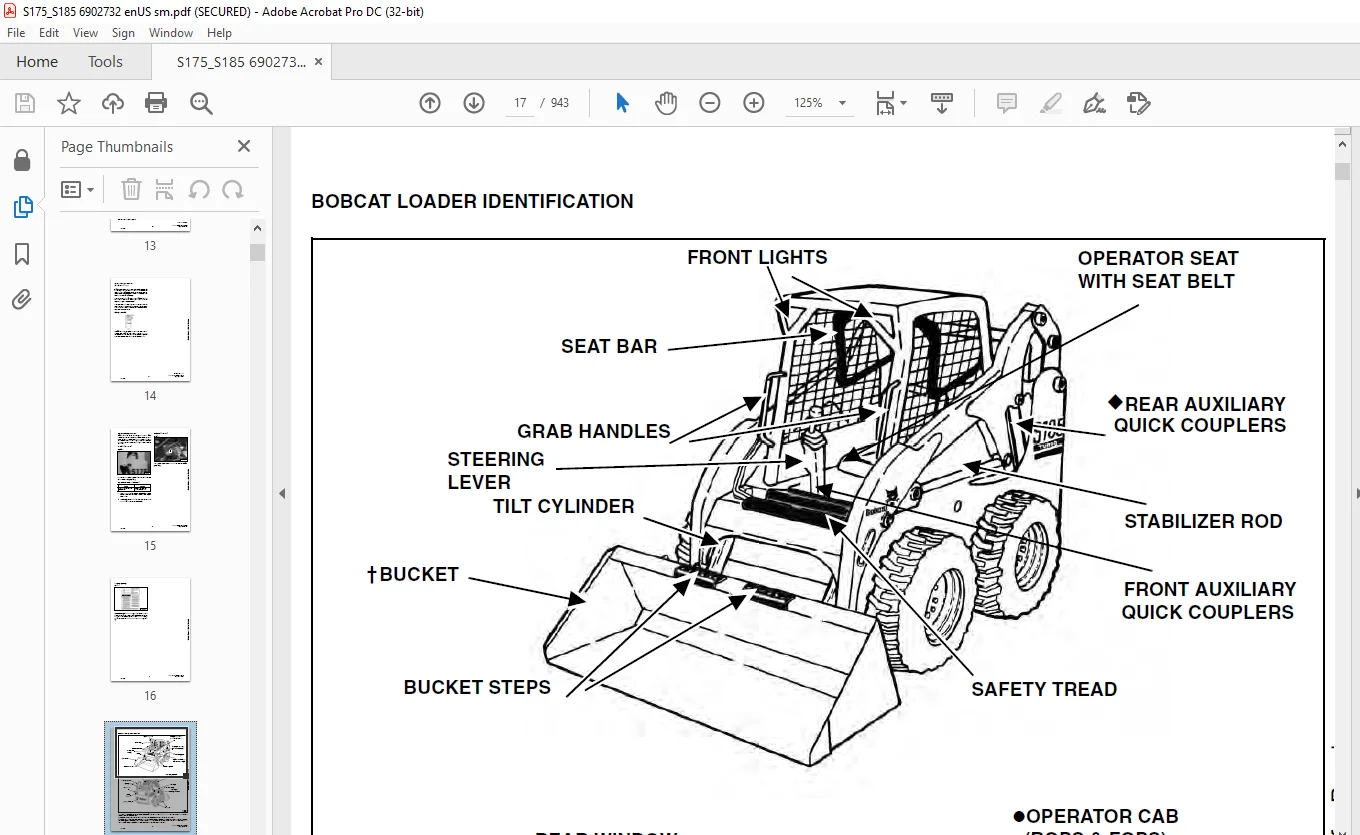
BOBCAT LOADER IDENTIFICATION 17
SAFETY AND MAINTENANCE 19
LIFTING AND BLOCKING THE LOADER 21
Procedure 21
LIFT ARM SUPPORT DEVICE 23
Installing Lift Arm Support Device 23
Removing Lift Arm Support Device 24
OPERATOR CAB 25
Description 25
Raising The Operator Cab 25
Lowering The Operator Cab 26
Emergency Exit 27
TRANSPORTING THE BOBCAT LOADER 29
Procedure 29
TOWING THE LOADER 31
Procedure 31
REMOTE START 33
Procedure 33
SERVICE SCHEDULE 37
Chart 37
AIR CLEANER SERVICE 39
Checking 39
Replacing Filter Element(s) 39
ENGINE COOLING SYSTEM 41
Cleaning The Cooling System 41
Checking The Coolant Level 42
Replacing the Coolant 42
FUEL SYSTEM 45
Fuel Specifications 45
Filling The Fuel Tank 45
Fuel Filter 46
Removing Air From The Fuel System 46
ENGINE LUBRICATION SYSTEM 47
Checking Engine Oil 47
Oil Chart 47
Replacing Oil And Filter 48
HYDRAULIC / HYDROSTATIC SYSTEM 49
Checking And Adding Fluid 49
Replacing Hydraulic / Hydrostatic Filter 49
Replacing Hydraulic Fluid 49
Breather Cap 51
FINAL DRIVE TRANSMISSION (CHAINCASE) 53
Checking And Adding Oil 53
Removing Oil From The Chaincase 53
FAN GEARBOX 55
Checking And Maintaining 55
BOB-TACH 57
Inspection And Maintenance 57
POWER BOB-TACH (OPTION) 59
Inspection And Maintenance 59
LUBRICATION OF THE BOBCAT LOADER 61
Procedure 61
TIRE MAINTENANCE 65
Wheel Nuts 65
Rotating 65
Mounting 65
SPARK ARRESTOR MUFFLER 67
Cleaning Procedure 67
HYDRAULIC SYSTEM 69
HYDRAULIC / HYDROSTATIC SCHEMATICS 75
HYDRAULIC SYSTEM INFORMATION 87
Troubleshooting Chart 91
CYLINDER (LIFT) 93
Checking 93
Removal And Installation 94
Identification 97
Disassembly 98
Assembly 99
CYLINDER (TILT) 103
Checking 103
Removal And Installation 104
Base End Pivot Pin Replacement 105
Rod End Pivot Pin Bushing And Seal Replacement 106
Parts Identification 107
Disassembly 108
Assembly 109
CYLINDER (POWER BOB-TACH) 113
Checking 113
Removal And Installation 114
Identification 115
Disassembly 116
Assembly 117
MAIN RELIEF VALVE 121
Checking 121
Adjustment 122
Removal and Installation 123
HYDRAULIC CONTROL VALVE (2 PIECE CASTING) (Foot control) 125
Identification 125
Removal And Installation 125
BICS Valve Removal And Installation 130
BICS Valve, Lift Arm Bypass Orifice Removal And Installation 131
BICS Valve, Check Valve Removal And Installation 132
BICS Valve Lock Valve Removal And Installation 133
BICS Valve Solenoid Removal And Installation 134
BICS Valve Solenoid Testing 135
Identification Chart 136
Load Check Valve 137
Main Relief Valve 138
Port Relief Valve 139
Anti-Cavitation Valve/Port Relief Valve 140
Anti-Cavitation Valve 140
Rubber Boot 141
Lift And Tilt Lock Block Removal And Installation 142
Lift Spool and Detent 142
Tilt Spool Removal And Installation 151
Auxiliary Spool Removal And Installation 153
Auxiliary Electric Solenoid 154
Port-Auxiliary Section 155
Cleaning And Inspection 156
HYDRAULIC CONTROL VALVE (2 PIECE CASTING) (ADVANCED CONTROL SYSTEM) (ACS) 157
Identification 157
Removal and Installation 157
BICS Valve Removal And Installation 161
BICS Valve, Lift Arm Bypass Orifice Removal And Installation 163
BICS Valve, Check Valve Removal And Installation 164
BICS Valve Lock Valve Removal And Installation 165
BICS Valve Solenoid Removal And Installation 166
BICS Valve Solenoid Testing 167
Actuator Removal And Installation 168
Identification Chart (ACS) 169
Lift Base End Restrictor 170
Load Check Valve 170
Main Relief Valve 171
Port Relief Valve 172
Anti-Cavitation Valve / Port Relief Valve 173
Anti-Cavitation Valve 174
Tilt Spool Removal And Installation 174
Lift Spool Removal And Installation 175
Lift and Tilt Spool Disassembly And Assembly 176
Auxiliary Spool Removal And Installation 177
Auxiliary Electric Solenoid 178
Port-Auxiliary Section 179
Cleaning And Inspection 179
HYDRAULIC CONTROL VALVE (1 PIECE CASTING) (FOOT CONTROL) 181
Identification 181
Removal And Installation 181
Identification Chart 186
Mount Bracket Removal and Installation 187
BICS Valve, Lift Load Check Valve Removal And Installation 187
Load Check Valve Removal And Installation (Tilt & Auxiliary) 188
Anti-Cavitation Valve (Lift, Rod End) 189
Port Relief/Anti-Cavitation Valve (Lift, Base End) 190
Port Relief/Anti-Cavitation Valve (Tilt, Base End) 190
Port Relief/Anti-Cavitation Valve (Tilt, Rod End) 191
Port Relief Valve 191
Plug Removal 192
Rubber Boot Removal and Installation 193
End Cap/Spool Lock Block Removal and Installation 194
Lift Spool and Detent Removal and Installation 195
Tilt Spool Removal and Installation 204
Auxiliary Spool Removal And Installation 206
Auxiliary Solenoid Disassembly and Assembly 208
BICS Valve Solenoid Disassembly And Assembly 209
BICS Valve, Lock Valve Removal And Installation 210
BICS Valve, Check Valve Removal And Installation 212
BICS Valve, Lift Arm Bypass Orifice Disassembly And Assembly 213
Main Relief Valve 213
HYDRAULIC CONTROL VALVE (1 PIECE CASTING) (ADVANCED CONTROL SYSTEM) (ACS) 215
Identification 215
Removal And Installation 215
Actuator Removal And Installation (Out of Loader) 220
Identification Chart (ACS) 223
Mount Bracket Removal and Installation 224
BICS Valve, Lift Load Check Valve Removal And Installation 224
Load Check Valve Removal And Installation (Tilt & Auxiliary) 225
Anti-Cavitation Valve (Lift, Rod End) 226
Port Relief/Anti-Cavitation Valve (Lift, Base End) 227
Port Relief/Anti-Cavitation Valve (Tilt, Base End) 227
Port Relief/Anti-Cavitation Valve (Tilt, Rod End) 228
Port Relief Valve 228
Plug Removal 229
End Cap Block Removal and Installation 230
Lift Spool Removal and Installation 231
Tilt Spool Removal and Installation 235
Auxiliary Spool Removal And Installation 237
Auxiliary Solenoid Disassembly and Assembly 238
BICS Valve Solenoid Disassembly And Assembly 239
BICS Valve, Lock Valve Removal And Installation 240
BICS Valve, Check Valve Removal And Installation 242
BICS Valve, Lift Arm Bypass Orifice Disassembly And Assembly 243
Main Relief Valve 243
LIFT ARM BYPASS CONTROL VALVE 245
Removal and Installation 245
Disassembly And Assembly 246
HYDRAULIC PUMP 247
Check The Output Of The Hydraulic Pump Without Power Bob-Tach 247
Check The Output Of The Hydraulic Pump With Power Bob-Tach 249
Removal And Installation 251
Identification 253
Disassembly And Assembly 254
HYDRAULIC PUMP (HIGH FLOW) 259
Check The Output Of The Hydraulic Pump Without Power Bob-Tach 259
Check The Output Of The Hydraulic Pump With Power Bob-Tach 261
Removal And Installation 263
Identification 265
Disassembly And Assembly 266
HYDRAULIC PUMP (SJC) 275
Test The Output Of The Hydraulic Auxiliary Pump 275
Test The Output Of The Hydraulic Charge Pump 276
Removal And Installation 278
Identification 280
Disassembly And Assembly 281
HYDRAULIC PUMP (HIGH FLOW) (SJC) 289
Test The Output Of The Hydraulic Auxiliary Pump 289
Test The Output Of The Hydraulic Charge Pump 290
Test The Output Of The Hydraulic Pump (High Flow) 292
Removal And Installation 294
Identification 297
Disassembly And Assembly 298
HYDRAULIC / HYDROSTATIC FILTER HOUSING 311
Removal And Installation 311
HYDRAULIC FLUID RESERVOIR 313
Fluid Removal 313
Removal And Installation 313
BUCKET POSITION VALVE 317
Solenoid Removal And Installation 317
Solenoid Testing 318
Removal And Installation 319
Disassembly And Assembly 321
HIGH FLOW VALVE 323
Checking The High Flow Relief Valve 323
High Flow Relief Valve Adjustment Procedure 325
Removal And Installation 326
Disassembly And Assembly 328
Solenoid Testing 330
REAR AUXILIARY DIVERTER VALVE 331
Removal And Installation 331
Disassembly And Assembly 334
Solenoid Testing 339
Inspection 339
POWER BOB-TACH BLOCK 341
Removal And Installation 341
Disassembly And Assembly 343
FRONT AUXILIARY HYDRAULIC COUPLER BLOCK 347
Removal and Installation 347
Disassembly And Assembly 347
HYDROSTATIC SYSTEM 349
HYDROSTATIC SYSTEM INFORMATION 351
Troubleshooting Chart 351
Replenishing Valve Function 352
HYDROSTATIC MOTOR 353
Description 353
Removal And Installation 353
Parts Identification (Wet Bolt) 355
Disassembly (Wet Bolt) 356
Assembly (Wet Bolt) 361
Parts Identification (Dry Bolt) 367
Disassembly and Assembly (Dry Bolt) 368
HYDROSTATIC MOTOR CARRIER 373
Shaft Seal Replacement 373
Removal And Installation 375
Parts Identification 377
Disassembly and Assembly 378
HYDROSTATIC MOTOR CARRIER (SJC) 383
Shaft Seal Replacement 383
Removal And Installation 385
Parts Identification 387
Disassembly and Assembly 388
CHARGE PRESSURE 393
Sender Removal And Installation (Non SJC Machines) 393
Testing (Non SJC Machines) 393
Adjusting (Non SJC Machines) 394
Sender Removal And Installation (SJC Machines) 395
Testing (SJC Machines) 395
Adjusting (SJC Machines) 396
HYDROSTATIC PUMP 397
Replenishing/High Pressure Relief Valve 397
Removal And Installation 398
Parts Identification (Right Half) 400
Parts Identification (Left Half) 402
Hydraulic Pump Removal And Installation 404
Pump Separation 404
Disassembly 405
Assembly 411
HYDROSTATIC PUMP (SJC) 419
Description 419
Hydraulic Controller Removal And Installation 420
Removal And Installation 422
Parts Identification 424
High Pressure Relief and Bypass Valve 425
Charge Relief Valve 426
Disassembly and Assembly 427
Mechanical Neutral Adjustment 443
Hydraulic Controller Neutral Adjustment 446
DRIVE BELT 449
Shield Removal And Installation 449
Adjusting 449
Drive Belt Replacement 451
Tensioner Pulley Removal And Installation 452
Tensioner Pulley Parts Identification 453
Tensioner Pulley Disassembly 454
Tensioner Pulley Assembly 455
OIL COOLER 457
Removal and Installation 457
DRIVE SYSTEM 459
BRAKE 461
Disk Removal And Installation 461
Switch Operated Parking Brake 462
DRIVE COMPONENTS 463
Axle Seal Removal And Installation 463
Axle Sprocket And Bearings Removal And Installation 465
Chain Removal And Installation 470
CHAINCASE 473
Checking And Adding Oil 473
Removing The Oil 473
General Information 474
Front Cover Removal And Installation 474
Center Cover Removal And Installation 475
Rear Cover Removal And Installation 476
MAIN FRAME 477
SEAT BAR 481
Removal And Installation 481
Assembling Components 482
Compression Spring Disassembly And Assembly 484
OPERATOR CAB 485
Gas Cylinder Removal And Installation 485
Gas Cylinder Disassembly 488
Removal And Installation 488
OPERATOR SEAT 491
Removal And Installation 491
Seat Belt Removal And Installation 491
OPERATOR SEAT (SUSPENSION) 493
Removal And Installation 493
Slide Rail Removal And Installation 494
Cushion Removal And Installation 494
Back Removal And Installation 496
Shock Removal And Installation 496
3-Point Seat Belt Removal And Installation 497
BOB-TACH 499
Removal And Installation 499
Bob-Tach Lever And Wedge 500
POWER BOB-TACH 503
Removal And Installation 503
Power Bob-Tach Lever And Wedge 504
LIFT ARM 507
Removal And Installation 507
Link Removal And Installation 511
Stabilizer Bar Removal And Installation 512
REAR GRILL 513
Removal And Installation 513
REAR DOOR 515
Removal And Installation 515
Striker Removal and Installation 516
Striker Disassembly and Assembly 516
Adjusting The Striker 516
Latch Removal and Installation 517
FUEL TANK 519
Removal And Installation 519
Fuel Level Sender 520
Fuel Fill Screen 520
CONTROL PEDALS 523
Removal And Installation 523
Pedal Adjustment 523
Crossbar Linkage Removal and Installation 524
Lift Foot Pedal Linkage Removal and Installation 525
Tilt Foot Pedal Linkage Removal and Installation 526
CONTROL PEDALS (ACS) 529
Foot Sensor Removal And Installation 529
Foot Pedal Removal And Installation 530
Foot Pedal Linkage Disassembly And Assembly 531
CONTROL PANEL (NON-ADJUSTABLE PINTLES) 533
Removal and Installation 533
Shock Removal And Installation 536
Shaft Removal And Installation 536
Shaft Disassembly And Assembly 536
Linkage Removal And Installation 537
Linkage Adjustment 540
Linkage Neutral Adjustment 544
CONTROL PANEL (ADJUSTABLE PINTLES) 547
Description 547
Removal and Installation 548
Shock Removal And Installation 551
Shaft Removal And Installation 551
Shaft Disassembly And Assembly 552
Linkage Removal And Installation 553
Pintle Arm Disassembly and Assembly 557
Linkage Neutral Adjustment 559
Linkage Travel Adjustment 563
CONTROL PANEL (SJC) 567
Removal And Installation 567
CONTROL HANDLE 569
Control Lever Removal And Installation 569
Control Lever Boot 569
CONTROL HANDLE (ADVANCED CONTROL SYSTEM) (ACS) 571
Components Identification 571
Handle Sensor Removal And Installation 572
Control Handle Removal and Installation 574
Control Handle Disassembly and Assembly 575
Control Lever Removal and Installation 576
Control Lever Boot 577
CONTROL HANDLE (SJC) 579
Joystick Testing (Right & Left) 579
Joystick Removal (Right & Left) 580
Lever Assembly Removal (Right & Left) 581
ELECTRICAL SYSTEM 583
ELECTRICAL SCHEMATICS 587
ELECTRICAL SYSTEM INFORMATION 594
Troubleshooting Chart 596
Description 597
Fuse Location 598
Relay Switch Location 598
BATTERY 600
Removal And Installation 600
Servicing 601
Using A Booster Battery (Jump Starting) 602
ALTERNATOR 604
Adjusting The Alternator Belt 604
Alternator Identification 604
Charging System Check 605
Alternator Voltage Test 606
Low Voltage Test 607
High Voltage Test 607
Removal And Installation 607
Rectifier Continuity (Diode) Test 608
Alternator Regulator Test 610
Disassembly 611
Stator Continuity Test 611
Stator Ground Test 611
Rotor Continuity Test 612
Rotor Ground Test 612
Assembly 612
STARTER 614
Checking 614
Removal And Installation 615
Parts Identification 616
Disassembly and Assembly 617
Inspection And Repair 620
No Load Test 622
INSTRUMENT PANEL 624
Left Panel 624
Right Panel (Standard) (With Key Switch) 625
Right Panel (Deluxe) (With Keyless Start) 626
Right Panel Setup Display Options (Deluxe) 628
Deluxe Panel Setup 629
Passwords (Deluxe) 629
Option And Field Accessory Panels (If Equipped) 631
Standard Panel Removal And Installation (Right Side) 632
Deluxe Panel Removal And Installation (Right Side) 633
Standard & Deluxe Panel Removal And Installation (Left Side) 634
Front Accessory Panel Removal And Installation 635
LIGHTS 636
Front Removal And Installation 636
Rear Removal And Installation 637
BOBCAT CONTROLLER 638
Identification Chart 638
Removal And Installation 640
CONTROLLER (SELECTABLE JOYSTICK CONTROL) (SJC) 642
Removal and Installation 642
Identification Chart 645
DIAGNOSTICS SERVICE CODES 648
Display 648
Number Codes List 649
BICS SYSTEM 656
Inspecting The BICS Controller (Engine STOPPED – Key ON) 656
Inspecting Deactivation Of The Auxiliary Hydraulics System (Engine STOPPED – Key ON) 656
Inspecting The Seat Bar Sensor (Engine RUNNING) 656
Inspecting The Traction Lock (Engine RUNNING) 656
Inspecting The Lift Arm Bypass Control 656
Additional Inspection For Loaders With Advanced Hand Controls (ACS) 657
Troubleshooting Chart 658
Troubleshooting Guide 659
SEAT BAR SENSOR 660
Troubleshooting Chart 660
Test 661
Removal And Installation 662
BICS Circuit Test 664
TRACTION LOCK 666
Troubleshooting Chart 666
Description Of The Control System 667
Inspecting The Control System 667
Inspecting 668
Solenoid Removal And Installation 668
Guide Removal 670
Guide Installation 672
ADVANCED CONTROL SYSTEM (ACS) 674
Components Identification 674
Troubleshooting Guide 676
Controller, Connector And Wire Identification 677
ACS Controller Removal And Installation 678
Handle Sensor Connector 679
Switch Handle Removal 680
Switch Handle Installation 682
Actuators Disassembly and Assembly 685
Handle Lock Solenoid Removal And Installation 687
Handle Lock Solenoid Disassembly And Assembly 687
Handle Lock Solenoid Connector 688
Calibration Procedure 689
Foot Sensor Disassembly And Assembly 691
Foot Sensor Connector 691
Foot Lock Solenoid Removal And Installation 692
Foot Lock Solenoid Connector 693
ELECTRICAL/HYDRAULIC CONTROLS REFERENCE 694
Controls Identification Chart 694
ELECTRICAL/HYDRAULIC CONTROLS REFERENCE (SELECTABLE JOYSTICK CONTROL) (SJC) 696
Controls Identification Chart 696
FLYWHEEL RPM SENSOR 700
Adjustment 700
SERVICE PC (LAPTOP COMPUTER) 702
Connecting The Service PC To Remote Start Tool 702
CALIBRATION 704
Description 704
Actuator Testing 704
Lift and Tilt Calibration Procedure (SJC) 707
Hydrostatic Pump Calibration (SJC) 708
Calibration Procedure (ACS) 714
SPEED SENSOR 716
Description 716
Testing 716
Removal and Installation 718
ENGINE SERVICE 720
TROUBLESHOOTING 722
Chart 722
ENGINE SPEED CONTROL 724
Removal And Installation 724
Disassembly 725
MUFFLER 726
Removal And Installation 726
AIR CLEANER 728
Removal And Installation 728
RADIATOR 730
Removal And Installation 730
COOLING FAN 734
Drive Tension Pulley Removal And Installation 734
Gearbox/Blower Housing Removal And Installation 735
Blower Housing Grill Removal And Installation 737
Blower Disassembly And Assembly 737
Gearbox Parts Identification 739
Gearbox Disassembly 740
Gearbox Assembly 745
Gearbox Checking Backlash 750
ENGINE COMPONENTS AND TESTING 754
Compression Checking 754
Glow Plugs Checking 755
Glow Plugs Removal And Installation 755
Fuel Shut-Off Solenoid, Checking 756
Fuel Shut-Off Solenoid Removal And Installation 757
Fuel Injection Pump Removal And Installation (Turbo) 758
Fuel Injection Pump Removal And Installation (Non- Turbo) 761
Timing The Injection Pump 765
Fuel Injector Removal And Installation 767
Checking Nozzle Injection Pressure 768
Nozzle Spraying Condition 769
Valve Seat Tightness 769
Valve Clearance Adjustment 770
Valve Timing, Checking 771
ENGINE 772
Removal And Installation 772
Engine Mount Replacement 780
FLYWHEEL AND HOUSING 782
Flywheel Removal And Installation 782
Ring Gear Removal And Installation 782
Housing Removal And Installation 783
RECONDITIONING THE ENGINE-V2203-M-DI AND V2003-M-DI-T (TURBO) 786
Cylinder Head Removal And Installation 786
Cylinder Head Disassembly And Assembly 789
Cylinder Head Servicing 790
Cylinder Head Top Clearance 790
Valve Guide Checking 791
Reconditioning The Valve And Valve Seat 793
Valve Spring 794
Rocker Arm And Shaft Checking 795
Timing Gearcase Cover Removal And Installation 795
Idler Gear And Camshaft Removal And Installation 798
Camshaft Servicing 799
Idler Gear And Shaft Servicing 800
Timing Gears Checking Backlash 801
Fuel Camshaft Removal And Installation 801
Fuel Camshaft Governor 802
Crankshaft Gear Removal And Installation 802
Oil Pump Removal And Installation 803
Oil Pump Service 803
Checking Engine Oil Pressure 804
Valve Tappets 805
Piston And Connecting Rod Removal And Installation 805
Piston And Connecting Rod Servicing 807
Connecting Rod Alignment 810
Crankshaft And Bearings Removal And Installation 810
Crankshaft And Bearings, Servicing 812
Cylinder Bore, Checking 816
Water Pump Removal And Installation 817
Water Pump Disassembly And Assembly 817
TURBOCHARGER 818
Checking 818
Description 818
Removal And Installation 819
HEATING, VENTILATION, AIR CONDITIONING 822
AIR CONDITIONING SYSTEM FLOW 825
Principals 825
Chart 826
COMPONENTS 828
Identification 828
SAFETY 832
Safety Equipment 832
REGULAR MAINTENANCE 834
Filter Elements Removal And Installation 834
Compressor Drive Belt Inspection 835
Cleaning The Condenser 836
BASIC TROUBLESHOOTING 838
Poor A/C Performance 838
Cleaning The A/C Evaporator Coil & Heater Coil 838
Compressor Drive Belt Inspection 839
Checking The Electrical System 840
Engine Coolant Bypassing The Heater Valve 847
Heater Valve Not Opening Or Closing 848
GENERAL AIR CONDITIONING SERVICE GUIDELINES 850
Compressor Oil 850
Compressor Oil Check 851
Component Replacement And Refrigeration Leaks 852
SYSTEM TROUBLESHOOTING CHART 854
Gauge Pressure Related Troubleshooting 855
TEMPERATURE/PRESSURE 858
Chart 858
AIR CONDITIONING SERVICE 860
Chart 860
SYSTEM CHARGING AND RECLAMATION 862
Reclamation Procedure 862
Charging Procedure With A Manifold Gauge Set 865
Charging Procedure 866
COMPRESSOR 870
Removal And Installation 870
Compressor Clutch Disassembly 871
CONDENSER 876
Removal And Installation 876
RECEIVER/DRIER 878
Removal And Installation 878
PRESSURE RELIEF VALVE 880
Removal And Installation 880
PRESSURE SWITCH 882
Removal And Installation 882
EVAPORATOR/HEATER UNIT 884
Removal And Installation 884
Disassembly And Assembly 886
THERMOSTAT 888
Removal And Installation 888
EXPANSION VALVE 890
Removal And Installation 890
EVAPORATOR 892
Removal And Installation 892
HEATER COIL 894
Removal And Installation With A/C 894
Removal And Installation Without A/C 895
HEATER/AC FAN 896
Removal And Installation 896
Disassembly And Assembly 897
Wire Connector Removal and Installation 899
HEATER VALVE 902
Removal And Installation 902
Disassembly And Assembly 902
SPECIFICATIONS 904
LOADER SPECIFICATIONS 906
Machine Dimensions 906
Performance 907
Controls 907
Engine 907
Hydraulic System 908
Electrical 908
Drive System 909
Capacities 909
Tires 909
ENGINE SPECIFICATIONS-KUBOTA V2203-M-DI 910
Fuel Injection Nozzles 910
Fuel Injection Pump 910
Cylinder Head 910
Valves 910
Valve Springs 911
Valve Timing 911
Rocker Arms 911
Camshaft 911
Tappet 911
Cylinders 912
Piston Rings 912
Pistons 912
Connecting Rod 912
Oil Pump 912
Crankshaft 913
Timing Gear 913
Thermostat 913
ENGINE SPECIFICATIONS – KUBOTA V2003-M-DI-T (TURBO) 914
Fuel Injection Nozzles 914
Fuel Injection Pump 914
Cylinder Head 914
Valves 914
Valve Springs 915
Valve Timing 915
Rocker Arms 915
Camshaft 915
Tappet 915
Cylinder Liner 916
Piston Rings 916
Pistons 916
Connecting Rod 916
Oil Pump 916
Crankshaft 917
Timing Gear 917
Thermostat 917
TORQUE SPECIFICATIONS FOR BOLTS 918
Torque For General SAE Bolts 918
Torque For General Metric Bolts 919
HYDRAULIC CONNECTION SPECIFICATIONS 920
O-ring Face Seal Connection 920
Straight Thread O-ring Fitting 921
Tubelines And Hoses 921
Flare Fitting 921
O-ring Flare Fitting 922
Port Seal Fitting 924
HYDRAULIC/HYDROSTATIC FLUID SPECIFICATIONS 926
Specifications 926
CONVERSIONS 928
Decimal And Millimeter Equivalents 928
U S To Metric Conversion 928
SERVICE MANUAL REVISION 930
Revision No: S175, S185 – 1 930
Revision No: S175, S185 – 2 932
Revision No: S175, S185 – 3 934
Revision No: S175, S185 – 4 936
Revision No: S175, S185 – 5 938
Revision No: S175, S185 – 6 940
Revision No: S175, S185 – 7 942
IMAGES PREVIEW OF THE MANUAL:
Customer Support: [email protected]
https://vimeo.com/843807614?share=copy
PLEASE NOTE:
- This is the SAME exact manual used by your dealers to fix your vehicle.
- The same can be yours in the next 2-3 mins as you will be directed to the download page immediately after paying for the manual.
- Any queries / doubts regarding your purchase, please feel free to contact [email protected]
S.V