Bobcat S175 Skid-Steer Loader Service Manual SN A8M460001 & Above – PDF DOWNLOAD
$33.95
Bobcat S175 Skid-Steer Loader Service Manual SN A8M460001 & Above – PDF DOWNLOAD
Description
Bobcat S175 Skid-Steer Loader Service Manual SN A8M460001 & Above – PDF DOWNLOAD
FILE DETAILS:
Bobcat S175 Skid-Steer Loader Service Manual SN A8M460001 & Above – PDF DOWNLOAD
Language : English
Pages : 842
Downloadable : Yes
File Type : PDF
DESCRIPTION:
Bobcat S175 Skid-Steer Loader Service Manual SN A8M460001 & Above – PDF DOWNLOAD
FOREWORD:
This manual is for the Bobcat loader mechanic. It provides necessary servicing and adjustment procedures for the Bobcat loader and its component parts and systems. Refer to the Operation & Maintenance Manual for operating instructions, starting procedure, daily checks, etc.
A general inspection of the following items must be made after the loader has had service or repair:
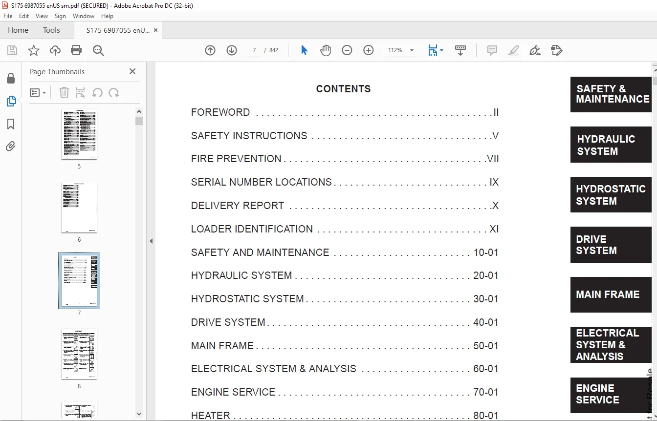
TABLE OF CONTENTS:
Bobcat S175 Skid-Steer Loader Service Manual SN A8M460001 & Above – PDF DOWNLOAD
MAINTENANCE SAFETY 3
ALPHABETICAL INDEX 5
CONTENTS 7
FOREWORD 8
SAFETY INSTRUCTIONS 11
FIRE PREVENTION 13
Maintenance 13
Operation 13
Electrical 13
Hydraulic System 13
Fueling 13
Starting 13
Spark Arrestor Exhaust System 13
Welding And Grinding 14
Fire Extinguishers 14
SERIAL NUMBER LOCATIONS 15
Loader Serial Number 15
Engine Serial Number 15
DELIVERY REPORT 16
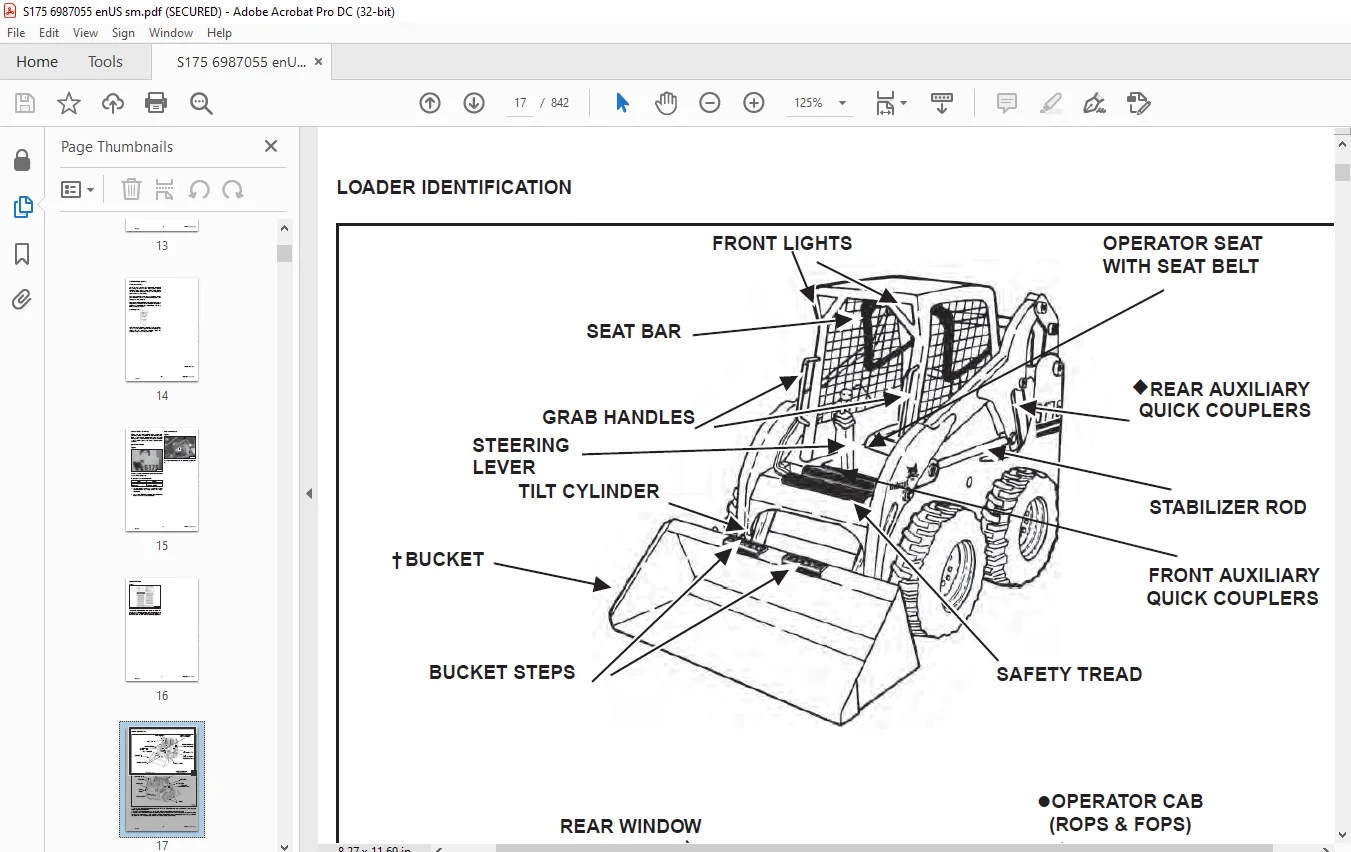
LOADER IDENTIFICATION 17
SAFETY AND MAINTENANCE 19
LIFTING AND BLOCKING THE LOADER 23
Procedure 23
LIFT ARM SUPPORT DEVICE 25
Installing 25
Removing 26
OPERATOR CAB 27
Description 27
Raising 28
Lowering 29
Cab Door Sensor 30
Special Applications Kit 30
Special Applications Kit Inspection And Maintenance 30
TRANSPORTING LOADER ON A TRAILER 31
Loading And Unloading 31
Fastening 31
TOWING THE LOADER 33
Procedure 33
REMOTE START TOOL KIT-MEL1563 35
Remote Start Tool – MEL1563 35
Service Tool Harness Control – MEL1565 36
Service Tool Harness Communicator – MEL1566 37
Remote Start Procedure 38
REMOTE START TOOL (SERVICE TOOL) KIT – 6689779 41
Description 41
Remote Start Tool (Service Tool) – 6689778 42
Loader Service Tool Harness – 6689747 43
Computer Service Tool Harness – 6689746 44
Remote Start Procedure 45
SERVICE SCHEDULE 49
Chart 49
AIR CLEANER SERVICE 51
Replacing Filter Elements 51
ENGINE COOLING SYSTEM 53
Cleaning 53
Checking Level 53
Removing And Replacing Coolant 54
FUEL SYSTEM 55
Fuel Specifications 55
Biodiesel Blend Fuel 55
Filling the Fuel Tank 56
Fuel Filter 57
Removing Air From The Fuel System 57
ENGINE LUBRICATION SYSTEM 59
Checking And Adding Engine Oil 59
Engine Oil Chart 59
Removing And Replacing Oil And Filter 60
HYDRAULIC/HYDROSTATIC SYSTEM 61
Checking And Adding Fluid 61
Hydraulic / Hydrostatic Fluid Chart 61
Removing And Replacing Hydraulic Fluid 62
Removing And Replacing Hydraulic/Hydrostatic Filter 62
Removing And Replacing Hydraulic Case Drain Filters (Single Speed Loaders) 63
Removing And Replacing Hydraulic Case Drain Filters (Two-Speed Loaders) 64
Removing And Replacing Hydraulic Charge Filter 66
Breather Cap 67
FINAL DRIVE TRANSMISSION (CHAINCASE) 69
Checking And Adding Oil 69
Removing And Replacing Oil 69
BOB-TACH (HAND LEVER) 71
Inspection And Maintenance 71
BOB-TACH (POWER) 73
Inspection And Maintenance 73
LUBRICATING THE LOADER 75
Lubrication Locations 75
TIRE MAINTENANCE 77
Wheel Nuts 77
Rotating 77
Mounting 77
SPARK ARRESTOR MUFFLER 79
Cleaning Procedure 79
PIVOT PINS 81
Inspection And Maintenance 81
LOADER STORAGE AND RETURN TO SERVICE 83
Storage 83
Return to Service 83
STOPPING THE ENGINE AND LEAVING THE LOADER 85
Procedure 85
Emergency Exit 86
HYDRAULIC SYSTEM 87
HYDRAULIC / HYDROSTATIC SCHEMATICS 91
HYDRAULIC SYSTEM INFORMATION 107
Glossary Of Hydraulic / Hydrostatic Symbols 107
Troubleshooting 111
CYLINDER (LIFT) 113
Testing 113
Removal And Installation 114
Parts Identification 116
Disassembly and Assembly 117
CYLINDER (TILT) 121
Testing 121
Removal And Installation 122
Base End Pivot Pin Removal And Installation 123
Rod End Pivot Pin Bushing And Seal Removal And Installation 124
Parts Identification 125
Disassembly And Assembly 126
CYLINDER (BOB-TACH) 129
Testing 129
Removal And Installation 130
Parts Identification 131
Disassembly and Assembly 132
MAIN RELIEF VALVE 135
Description 135
Testing 135
Adjusting 136
Removal and Installation 137
HYDRAULIC CONTROL VALVE (STANDARD) 139
Description 139
Removal And Installation 139
Identification Chart 144
Mount Bracket Removal And Installation 145
Lift Load Check Valve Removal And Installation 145
Load Check Valve Removal And Installation (Tilt & Auxiliary) 146
Anti-Cavitation Valve Removal And Installation (Lift, Rod End) 147
Port Relief/Anti-Cavitation Valve Removal And Installation (Lift, Base End) 148
Port Relief/Anti-Cavitation Valve Removal And Installation (Tilt, Base End) 148
Port Relief/Anti-Cavitation Valve Removal And Installation (Tilt, Rod End) 149
Port Relief Valve Removal And Installation 149
Plug Removal And Installation 150
Rubber Boot Removal And Installation 151
End Cap/Spool Lock Block Removal And Installation 152
Lift Spool And Detent Removal And Installation 153
Tilt Spool Removal And Installation 163
Auxiliary Spool Removal And Installation 165
Auxiliary Solenoid Removal And Installation 166
Solenoid Removal And Installation 167
Lock Valve Removal And Installation 169
Lift Arm Bypass Orifice Removal And Installation 171
Main Relief Valve Removal And Installation 171
Check Valve Removal And Installation 172
HYDRAULIC CONTROL VALVE (ACS) OR (SJC) 173
Description 173
Removal And Installation 173
Actuator Removal And Installation (Out of Loader) 178
Identification Chart 181
Mount Bracket Removal And Installation 182
Lift Load Check Valve Removal And Installation 182
Load Check Valve Removal And Installation (Tilt & Auxiliary) 183
Anti-Cavitation Valve Removal And Installation (Lift, Rod End) 184
Port Relief/Anti-Cavitation Valve Removal And Installation (Lift, Base End) 185
Port Relief/Anti-Cavitation Valve Removal And Installation (Tilt, Base End) 185
Port Relief/Anti-Cavitation Valve Removal And Installation (Tilt, Rod End) 186
Port Relief Valve Removal And Installation 186
Plug Removal And Installation 187
End Cap Block Removal And Installation 188
Lift Spool And Detent Removal And Installation 189
Tilt Spool Removal And Installation 194
Auxiliary Spool Removal And Installation 196
Auxiliary Solenoid Removal And Installation 198
Solenoid Removal And Installation 199
Lock Valve Removal And Installation 200
Lift Arm Bypass Orifice Removal And Installation 201
Main Relief Valve Removal And Installation 202
Check Valve Removal And Installation 203
LIFT ARM BYPASS CONTROL VALVE 205
Description 205
Testing 205
Removal and Installation 205
Disassembly And Assembly 206
HYDRAULIC PUMP (STANDARD) 207
Description 207
Pump Test at Quick Couplers 207
Direct Pump Test (Standard Section) 208
Direct Pump Test (Charge Section) 210
Removal And Installation 212
Parts Identification 214
Disassembly And Assembly 215
Hydraulic Pump Start Up 223
HYDRAULIC PUMP (STANDARD) (HIGH FLOW) 225
Description 225
Pump Test at Quick Couplers 225
Direct Pump Test (Standard Section) 226
Direct Pump Test (Charge Section) 228
Direct Pump Test (High Flow Section) 230
Removal And Installation 232
Parts Identification 234
Disassembly And Assembly 235
Hydraulic Pump Start Up 247
HYDRAULIC PUMP (SJC) 249
Description 249
Pump Test at Quick Couplers 249
Direct Pump Test (Standard Section) 250
Direct Pump Test (Charge Section) 252
Removal And Installation 254
Parts Identification 256
Disassembly And Assembly 257
Hydraulic Pump Start Up 265
HYDRAULIC PUMP (SJC) (HIGH FLOW) 267
Description 267
Pump Test at Quick Couplers 267
Direct Pump Test (Standard Section) 268
Direct Pump Test (Charge Section) 270
Direct Pump Test (High Flow Section) 272
Removal And Installation 274
Parts Identification 276
Disassembly And Assembly 277
Hydraulic Pump Start Up 289
HYDRAULIC/HYDROSTATIC FILTERS 291
Description 291
Housing Removal And Installation 291
Charge Filter Housing Removal And Installation 293
HYDRAULIC FLUID RESERVOIR 295
Description 295
Removal And Installation 295
Hydraulic Fluid Screen 298
OIL COOLER 299
Description 299
Removal and Installation 299
BUCKET POSITION VALVE 301
Description 301
Solenoid Removal And Installation 301
Solenoid Testing 302
Removal And Installation 303
Disassembly And Assembly 304
REAR AUXILIARY DIVERTER VALVE 307
Description 307
Removal And Installation 307
Disassembly And Assembly 310
Solenoid Testing 316
POWER BOB-TACH BLOCK 317
Description 317
Removal And Installation 317
Disassembly And Assembly 319
FRONT AUXILIARY HYDRAULIC COUPLER BLOCK 323
Description 323
Removal and Installation 323
Disassembly And Assembly 323
HIGH FLOW VALVE 325
Description 325
High Flow Relief Valve Testing 325
High Flow Relief Valve Adjustment 326
Solenoid Testing 326
Removal And Installation 326
Disassembly And Assembly 326
HYDROSTATIC SYSTEM 333
HYDROSTATIC SYSTEM INFORMATION 335
Troubleshooting 335
Description 336
HYDROSTATIC MOTOR 337
Description 337
Removal And Installation 337
Parts Identification 340
Disassembly and Assembly 341
HYDROSTATIC MOTOR (TWO-SPEED) 347
Description 347
Removal And Installation (Left Side) 348
Removal And Installation (Right Side) 351
Parts Identification 354
Disassembly 355
Assembly 365
HYDROSTATIC MOTOR CARRIER (SINGLE AND TWO- SPEED WITH MANUAL CONTROLS) 377
Description 377
Shaft Seal Removal And Installation 377
Removal And Installation 379
Parts Identification 381
Disassembly and Assembly 382
HYDROSTATIC MOTOR CARRIER (SINGLE AND TWO- SPEED WITH SJC CONTROLS) 387
Description 387
Shaft Seal Removal And Installation 387
Removal And Installation 389
Parts Identification 391
Disassembly and Assembly 392
CHARGE PRESSURE 397
Description 397
Testing 397
Sender Removal And Installation 398
Adjusting 399
HYDROSTATIC PUMP 401
Description 401
Replenishing/High Pressure Relief Valve 401
Removal And Installation 402
Hydrostatic Pump Start Up 403
Parts Identification (Left Half) 404
Parts Identification (Right Half) 405
Disassembly 406
Assembly 412
HYDROSTATIC PUMP (SJC) 419
Description 419
Hydraulic Controller Removal And Installation 420
Removal And Installation 422
Hydrostatic Pump Start Up 424
Parts Identification 425
High Pressure Relief and Bypass Valve 426
Charge Relief Valve 427
Disassembly and Assembly 428
Mechanical Neutral Adjustment 443
Hydraulic Controller Neutral Adjustment 446
DRIVE BELT 449
Description 449
Shield Removal And Installation 449
Adjusting 449
Belt Removal And Installation 451
Belt Tensioner Removal And Installation 452
Belt Tensioner Parts Identification 453
Belt Tensioner Disassembly 454
Belt Tensioner Assembly 455
TWO-SPEED VALVE 457
Description 457
Valve Removal And Installation 457
Valve Disassembly And Assembly 459
CASE DRAIN FILTER 461
Description 461
Disassembly And Assembly 461
DRIVE SYSTEM 463
BRAKE (SINGLE SPEED) 465
Description 465
Disc Removal And Installation 465
BRAKE (TWO-SPEED) 467
Description 467
Disc Removal And Installation 467
Disc Disassembly and Assembly 468
DRIVE COMPONENTS 469
Description 469
Axle Seal Removal And Installation 470
Axle Sprocket And Bearings Removal And Installation 472
Chain Removal And Installation 477
CHAINCASE 479
Description 479
Front Cover Removal And Installation 479
Center Cover Removal And Installation 480
Rear Cover Removal And Installation 481
MAIN FRAME 483
SEAT BAR 487
Description 487
Removal And Installation 487
Disassembly And Assembly 488
Compression Spring Disassembly And Assembly 490
OPERATOR CAB 491
Gas Cylinder Removal And Installation 491
Gas Cylinder Bracket Disassembly And Assembly 494
Removal And Installation 494
OPERATOR SEAT 497
Removal And Installation 497
Seat Belt Removal And Installation 497
OPERATOR SEAT (SUSPENSION) 499
Removal And Installation 499
Slide Rail Removal And Installation 500
Seat Belt Removal and Installation 500
Lower Cushion Removal And Installation 501
Back Cushion Removal And Installation 502
Shock Removal And Installation 502
3-Point Seat Belt Removal And Installation 503
BOB-TACH (HAND LEVER) 505
Description 505
Removal And Installation 505
Lever And Wedge Disassembly And Assembly 506
Pivot Pin Bushing And Seal Removal And Installation 508
BOB-TACH (POWER-OPTION) 509
Description 509
Removal And Installation 509
Lever And Wedge Disassembly And Assembly 511
Pivot Pin Bushing And Seal Removal And Installation 512
LIFT ARMS 513
Stabilizer Bar Removal And Installation 513
Link Removal And Installation 514
Removal And Installation 515
REAR GRILL 519
Removal And Installation 519
REAR DOOR 521
Removal And Installation 521
Striker Removal and Installation 522
Striker Disassembly and Assembly 522
Striker (Adjusting) 523
Latch Removal and Installation 523
FUEL TANK 525
Removal And Installation 525
Fuel Level Sender Removal And Installation 526
Fuel Fill Screen Removal And Installation 526
CONTROL PEDALS AND LINKAGES 527
Description 527
Pedal Removal And Installation 527
Linkage Removal And Installation 528
Pedal (Adjusting) 530
CONTROL PEDALS (ACS) 531
Description 531
Foot Sensor Removal And Installation 531
Foot Pedal Removal And Installation 532
Foot Pedal Linkage Disassembly And Assembly 532
CONTROL PANEL 533
Description 533
Removal and Installation 534
Shock Removal And Installation 537
Shaft Removal And Installation 537
Shaft Disassembly And Assembly 538
Linkage Removal And Installation 539
Pintle Arm Disassembly and Assembly 543
Linkage Neutral Adjustment 544
Linkage Travel Adjustment 544
CONTROL PANEL (SJC) 551
Description 551
Removal And Installation 551
CONTROL HANDLE/LEVER 553
Description 553
Lever Removal And Installation 553
Boot Removal And Installation 554
CONTROL HANDLE/LEVER (ACS) 555
Description 555
Handle Sensor Removal And Installation 555
Handle Removal And Installation 558
Handle Disassembly And Assembly 559
Lever Removal And Installation 559
Boot Removal And Installation 560
CONTROL HANDLE/LEVER (SJC) 561
Description 561
Joystick Testing 562
Joystick Removal And Installation 563
Removal And Installation 564
Removal And Installation (Left) 565
Removal And Installation (Right) 565
ACCESS PANEL (INSIDE) 565
Removal And Installation (Left) 565
Removal And Installation (Right) 565
ACCESS PANEL (INSIDE) (SJC) 567
Removal And Installation (Left) 567
Removal And Installation (Right) 568
WINDOW (REAR) 571
Removal 571
Installation 571
WINDOW (TOP) 573
Removal And Installation 573
WINDOW (SIDE) 575
Removal And Installation 575
WINDOW (FRONT DOOR) 577
Removal (Standard Window) 577
Installation (Standard Window) 578
Removal And Installation (Special Applications Window) 580
ELECTRICAL SYSTEM & ANALYSIS 581
ELECTRICAL SCHEMATICS 585
ELECTRICAL SYSTEM INFORMATION 591
Glossary Of Electrical Symbols 591
Standard Cab Harness Connectors 594
Deluxe Cab Harness Connectors 595
Mainframe Harness Connectors 596
Description 597
Troubleshooting 598
Fuse And Relay Location / Identification 599
Solenoid Testing 600
BATTERY 601
Removal And Installation 601
Servicing 602
Using A Booster Battery (Jump Starting) 603
ALTERNATOR 605
Belt Adjustment 605
Belt Replacement 605
Charging System Inspection 606
Alternator Voltage Testing 607
Low Voltage Testing 607
High Voltage Testing 608
Removal And Installation 609
Parts Identification 610
STARTER 611
Testing 611
Removal And Installation 611
Parts Identification 612
INSTRUMENT PANELS 613
Left Panel 613
Standard Key Panel 615
Deluxe Instrumentation Panel 616
Side Panel 617
Front Panel 617
Front Panel Removal And Installation 618
Removal And Installation (Left And Right) 618
Key Switch Removal And Installation 620
Alarm Removal And Installation 620
BOBCAT CONTROLLERS (GATEWAY AND AUXILIARY) 621
Description 621
Connector Identification 622
Removal And Installation 628
LIGHTS 629
Front Removal And Installation 629
Rear Removal And Installation 630
Cab Light Removal And Installation 630
BOBCAT CONTROLLER (ACS) 631
Description 631
Connector Identification 632
Removal And Installation 633
BOBCAT CONTROLLER (SJC) (DRIVE) 635
Description 635
Connector Identification 636
Removal And Installation 638
SPEED SENSORS (SJC) 641
Description 641
Testing 641
Removal And Installation 643
DIAGNOSTIC SERVICE CODES 645
Viewing Service Codes (Standard Key Panel) 645
Viewing Service Codes (Deluxe Instrumentation Panel) 645
Service Codes List 646
BOBCAT INTERLOCK CONTROL SYSTEM (BICS) 651
Description 651
Inspecting The BICS Controller (Engine STOPPED – Key ON) 652
Inspecting Deactivation Of The Auxiliary Hydraulics System (Engine STOPPED – Key ON) 652
Inspecting The Seat Bar Sensor (Engine RUNNING) 652
Inspecting The Traction Lock (Engine RUNNING) 652
Inspecting The Lift Arm Bypass Control 652
Inspecting Deactivation Of Lift And Tilt Functions (ACS And SJC) 652
Troubleshooting 653
SEAT BAR SENSOR 655
Description 655
Troubleshooting 655
Testing 656
Removal And Installation 657
Bobcat Interlock Control System (BICS) Circuit Test 658
TRACTION LOCK 659
Description 659
Troubleshooting 659
Removal And Installation 660
Inspecting 664
CONTROL SYSTEM (ACS) 665
Description 665
Troubleshooting Chart 666
Handle Sensor Connector Disassembly And Assembly 667
Switch Handle Removal 668
Switch Handle Installation 670
Actuator Connector Disassembly And Assembly 673
Handle Lock Solenoid Removal And Installation 674
Handle Lock Solenoid Disassembly And Assembly 675
Foot Sensor Disassembly And Assembly 675
Foot Lock Solenoid Removal And Installation 676
ELECTRICAL/HYDRAULIC CONTROLS 677
Identification Chart 677
ELECTRICAL/HYDRAULIC CONTROLS (SJC) 679
Identification Chart 679
SERVICE PC (LAPTOP COMPUTER) 683
Connecting Remote Start Tool 683
Connecting Remote Start Tool (Service Tool) 683
CALIBRATION 685
Description 685
Actuator Testing 685
Lift And Tilt Calibration (ACS) 687
Lift And Tilt Calibration (SJC) 689
Hydrostatic Pump Calibration (SJC) 691
STEERING DRIFT COMPENSATION 697
Description 697
Operation 697
FLYWHEEL RPM SENSOR 699
Description 699
Adjusting 699
CONTROL PANEL SETUP 701
Right Panel Setup (Deluxe Instrumentation Panel) 701
Attachment Control Information (Deluxe Instrumentation Panel) 702
PASSWORD SETUP 703
Password Description 703
Changing The Owner Password 703
Changing The User Passwords 704
Password Lockout Feature 704
MAINTENANCE CLOCK 705
Description 705
Setup 706
Reset 709
BACK-UP ALARM SYSTEM 711
Description 711
Inspecting 712
Adjusting Switch Position 712
Troubleshooting (Standard And ACS) 713
Troubleshooting (Joystick) 714
Alarm Removal And Installation 715
Switch Removal And Installation 715
ENGINE SERVICE 717
ENGINE INFORMATION 719
Description 719
Specifications 720
Engine Torque Values 723
Troubleshooting 723
Engine Removal And Installation 725
Engine Mount Replacement 732
Compression – Checking 733
ENGINE SPEED CONTROL 735
Removal And Installation 735
ENGINE SPEED CONTROL (SJC) 737
Removal And Installation 737
Disassembly And Assembly 739
MUFFLER 741
Removal And Installation 741
AIR CLEANER 743
Housing Removal And Installation 743
ENGINE COOLING SYSTEM 745
Radiator Removal And Installation 745
Blower Housing Removal And Installation 748
Hydraulic Fan Removal And Installation 750
Hydraulic Fan Description 751
Hydraulic Fan Disassembly And Assembly 751
Water Pump Removal And Installation 752
Water Pump Disassembly And Assembly 752
Thermostat Housing Removal And Installation 753
LUBRICAITON SYSTEM 755
Oil Pan Removal And Installation 755
Oil Pump Removal And Installation 755
Oil Pump Inspection 756
Engine Oil Pressure – Testing 757
FUEL SYSTEM 759
Fuel Camshaft Removal And Installation 759
Fuel Camshaft Governor Disassembly And Assembly 760
Fuel Shut Off Solenoid – Checking 761
Fuel Shut Off Solenoid Removal And Installation 761
Fuel Injection Pump Removal And Installation 762
Injection Pump – Timing 766
Fuel Injector Removal And Installation 768
Fuel Injector Nozzle Pressure – Checking 769
Nozzle Spray Condition 770
Valve Seat Tightness 770
CYLINDER HEAD 771
Glow Plugs – Testing 771
Glow Plugs Removal And Installation 771
Valve Clearance Adjustment 772
Valve Timing – Checking 773
Cylinder Head Removal And Installation 774
Cylinder Head Disassembly And Assembly 777
Cylinder Head – Servicing 777
Cylinder Head Top Clearance 778
Valve Guide – Checking 778
Reconditioning The Valve And Valve Seat 779
Valve Spring 781
Valve Tappets 782
Rocker Arm And Shaft Checking 782
CRANKSHAFT AND PISTONS 783
Piston And Connecting Rod Removal And Installation 783
Piston And Connecting Rod – Servicing 785
Cylinder Bore – Checking 787
Connecting Rod Alignment 787
Crankshaft And Bearings Removal And Installation 788
Crankshaft And Bearings – Servicing 790
Timing Gearcase Cover Removal And Installation 793
Timing Gears Backlash – Checking 795
Idler Gear And Shaft Removal And Installation 796
Camshaft – Servicing 797
FLYWHEEL AND HOUSING 799
Idler Gear And Shaft Servicing 798
Flywheel Removal And Installation 799
Ring Gear Removal And Installation 799
Housing Removal And Installation 800
HEATER 803
HEATER SYSTEM 805
Description 805
REGULAR MAINTENANCE 807
Filter Elements Removal And Installation 807
Cleaning The Heater Coil 808
TROUBLESHOOTING 809
Blower Motor Does Not Operate 809
Blower Motor Operates Normally, But Air Flow Is Insufficient 809
Electrical System 810
Engine Coolant Bypassing The Heater Valve 814
Heater Valve Not Opening Or Closing 815
HEATER UNIT 817
Removal And Installation 817
HEATER COIL 819
Removal And Installation 819
HEATER FAN 821
Blower Removal And Installation 821
Disassembly And Assembly 822
Connector Identification 824
HEATER VALVE 825
Removal And Installation 825
Disassembly And Assembly 826
SPECIFICATIONS 827
LOADER SPECIFICATIONS 829
Dimensions 829
Performance 830
Controls 830
Engine 830
Hydraulic System 831
Electrical 831
Drive System 832
Capacities 832
Tires 832
TORQUE SPECIFICATIONS FOR BOLTS 833
Torque For General SAE Bolts 833
Torque For General Metric Bolts 834
HYDRAULIC CONNECTION SPECIFICATIONS 835
O-ring Face Seal Connections 835
Straight Thread O-ring Fitting 836
Tubelines And Hoses 836
Flare Fitting 836
Port Seal Fitting 837
HYDRAULIC/HYDROSTATIC FLUID SPECIFICATIONS 839
Specifications 839
CONVERSIONS 841
Decimal And Millimeter Equivalents 841
U S To Metric Conversion Chart 841
IMAGES PREVIEW OF THE MANUAL:
Need help? Contact: [email protected]
PLEASE NOTE:
- This is the SAME MANUAL used by the dealerships to diagnose your vehicle
- No waiting for couriers / posts as this is a PDF manual and you can download it within 2 minutes time once you make the payment.
- Your payment is all safe and the delivery of the manual is INSTANT – You will be taken to the DOWNLOAD PAGE.
- So have no hesitations whatsoever and write to us about any queries you may have : heydownloadss @gmail.com
S.V