Bobcat S185 Skid-Steer Loader Service Manual 6987049 (01-15) – PDF DOWNLOAD
$34.95
Bobcat S185 Skid-Steer Loader Service Manual 6987049 (01-15) – PDF DOWNLOAD
S/N A3L911001 & Above
S/N A3LH11001 & Above
S/N AEYU11001 & Above
Description
Bobcat S185 Skid-Steer Loader Service Manual 6987049 (01-15) – PDF DOWNLOAD
FILE DETAILS:
Bobcat S185 Skid-Steer Loader Service Manual 6987049 (01-15) – PDF DOWNLOAD
Language : English
Pages : 994
Downloadable : Yes
File Type : PDF
DESCRIPTION:
Bobcat S185 Skid-Steer Loader Service Manual 6987049 (01-15) – PDF DOWNLOAD
S/N A3L911001 & Above
S/N A3LH11001 & Above
S/N AEYU11001 & Above
FOREWORD:
This manual is for the Bobcat loader mechanic. It provides necessary servicing and adjustment procedures for the Bobcat loader and its component parts and systems. Refer to the Operation & Maintenance Manual for operating instructions, starting procedure, daily checks, etc.
A general inspection of the following items must be made after the loader has had service or repair:
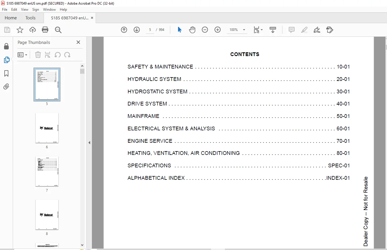
TABLE OF CONTENTS:
Bobcat S185 Skid-Steer Loader Service Manual 6987049 (01-15) – PDF DOWNLOAD
MAINTENANCE SAFETY 3
CONTENTS 5
FOREWORD 7
FOREWORD 9
SAFETY INSTRUCTIONS 12
FIRE PREVENTION 14
Maintenance 14
Operation 14
Electrical 14
Hydraulic System 14
Fueling 14
Starting 14
Spark Arrester Exhaust System 14
Welding And Grinding 15
Fire Extinguishers 15
SERIAL NUMBER LOCATIONS 16
Loader Serial Number 16
Engine Serial Number 16
DELIVERY REPORT 17
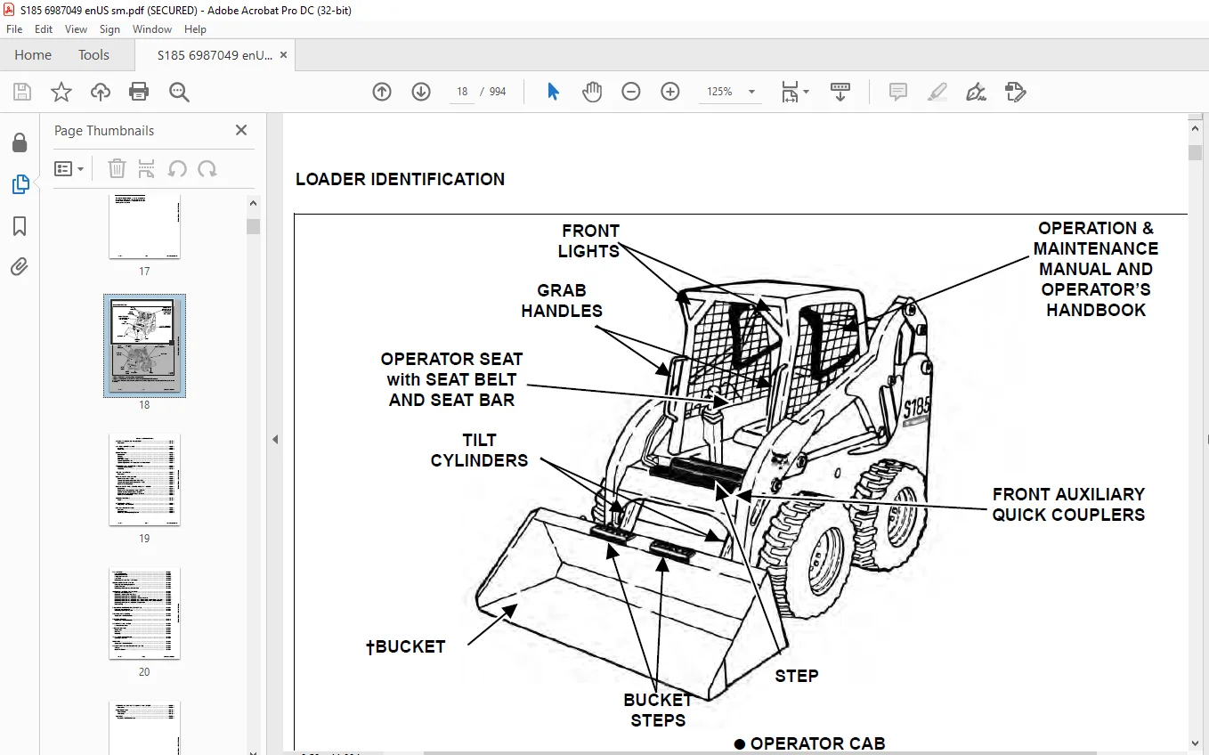
LOADER IDENTIFICATION 18
SAFETY & MAINTENANCE 19
LIFTING AND BLOCKING THE LOADER 23
Procedure 23
LIFT ARM SUPPORT DEVICE 25
Installing 25
Removing 26
OPERATOR CAB 27
Description 27
Raising 27
Lowering 28
Cab Door Sensor 29
Special Applications Kit 30
Special Applications Kit Inspection And Maintenance 30
TRANSPORTING LOADER ON A TRAILER 31
Loading And Unloading 31
Fastening 31
TOWING THE LOADER 33
Procedure 33
REMOTE START TOOL KIT-1563 35
Remote Start Tool – 1563 35
Service Tool Harness Control – MEL1565 36
Service Tool Harness Communicator – 1566 37
Remote Start Procedure 38
REMOTE START TOOL (SERVICE TOOL) KIT – 7003031 41
Description 41
Remote Start Tool (Service Tool) – 7003030 42
Loader Service Tool Harness – 6689747 43
Computer Service Tool Harness – 6689746 44
Remote Start Procedure 45
SERVICE SCHEDULE 49
Chart 49
AIR CLEANER SERVICE 51
Replacing Filter Elements 51
ENGINE COOLING SYSTEM 53
Cleaning 53
Checking Level 54
Removing And Replacing Coolant 55
FUEL SYSTEM 57
Fuel Specifications 57
Biodiesel Blend Fuel 57
Filling The Fuel Tank 58
Fuel Filter 59
Removing Air From The Fuel System 59
ENGINE LUBRICATION SYSTEM 61
Checking And Adding Engine Oil 61
Engine Oil Chart 61
Removing And Replacing Oil And Filter 62
HYDRAULIC / HYDROSTATIC SYSTEM 63
Checking And Adding Fluid 63
Hydraulic / Hydrostatic Fluid Chart 63
Removing And Replacing Hydraulic Fluid 64
Removing And Replacing Hydraulic / Hydrostatic Filter 64
Removing And Replacing Hydraulic Case Drain Filters (Single Speed Loaders) 65
Removing And Replacing Hydraulic Case Drain Filters (Two-Speed Loaders) 66
Removing And Replacing Hydraulic Charge Filter 68
Breather Cap 70
FINAL DRIVE TRANSMISSION (CHAINCASE) 71
Checking And Adding Oil 71
Removing And Replacing Oil 71
BOB-TACH (HAND LEVER) 73
Inspection And Maintenance 73
BOB-TACH (POWER) 75
Inspection And Maintenance 75
LUBRICATING THE LOADER 77
Lubrication Locations 77
TIRE MAINTENANCE 79
Wheel Nuts 79
Rotating 79
Mounting 79
SPARK ARRESTER MUFFLER 81
Cleaning Procedure 81
PIVOT PINS 83
Inspection And Maintenance 83
LOADER STORAGE AND RETURN TO SERVICE 85
Storage 85
Return To Service 85
STOPPING THE ENGINE AND LEAVING THE LOADER 87
Procedure 87
EMERGENCY EXIT 89
Rear Window 89
Front Door 89
SEAT BELT 91
Inspection And Maintenance 91
HYDRAULIC SYSTEM 93
HYDRAULIC / HYDROSTATIC SCHEMATICS 99
HYDRAULIC SYSTEM INFORMATION 115
Glossary Of Hydraulic / Hydrostatic Symbols 115
Troubleshooting 119
CYLINDER (LIFT) 121
Testing 121
Removal And Installation 122
Parts Identification 125
Disassembly And Assembly 126
CYLINDER (TILT) 129
Testing 129
Removal And Installation 130
Rod End Pivot Pin Bushing And Seal Removal And Installation 132
Base End Pivot Pin Removal And Installation 132
Parts Identification 133
Disassembly And Assembly 134
CYLINDER (BOB-TACH) 137
Testing 137
Removal And Installation 138
Parts Identification 139
Disassembly And Assembly 140
MAIN RELIEF VALVE 143
Description 143
Testing 144
Adjusting 146
Removal And Installation 147
HYDRAULIC CONTROL VALVE (STANDARD) 149
Description 149
Removal And Installation 150
Identification Chart 155
Mount Bracket Removal And Installation 156
Lift Load Check Valve Removal And Installation 156
Load Check Valve Removal And Installation (Tilt And Auxiliary) 157
Anti-Cavitation Valve Removal And Installation (Lift, Rod End) 158
Port Relief / Anti-Cavitation Valve Removal And Installation (Lift, Base End) 159
Port Relief / Anti-Cavitation Valve Removal And Installation (Tilt, Base End) 159
Port Relief / Anti-Cavitation Valve Removal And Installation (Tilt, Rod End) 160
Port Relief Valve Removal And Installation 160
Plug Removal And Installation 161
Rubber Boot Removal And Installation 162
End Cap / Spool Lock Block Removal And Installation 163
Lift Spool And Detent Removal And Installation 164
Tilt Spool Removal And Installation 174
Auxiliary Spool Removal And Installation 176
Auxiliary Solenoid Removal And Installation (S/N A3L934999 & Below And A3LH34999 & Below) 178
Auxiliary Solenoid Removal And Installation (S/N A3L935001 & Above And A3LH35001 & Above) 179
Solenoid Removal And Installation 180
Lock Valve Removal And Installation 181
Lift Arm Bypass Orifice Removal And Installation 183
Main Relief Valve Removal And Installation 183
Check Valve Removal And Installation 184
HYDRAULIC CONTROL VALVE (ACS) OR (SJC) 185
Description 185
Removal And Installation 186
Actuator Removal And Installation (Out Of Loader) 190
Identification Chart 193
Mount Bracket Removal And Installation 194
Lift Load Check Valve Removal And Installation 194
Load Check Valve Removal And Installation (Tilt And Auxiliary) 195
Anti-Cavitation Valve Removal And Installation (Lift, Rod End) 196
Port Relief / Anti-Cavitation Valve Removal And Installation (Lift, Base End) 197
Port Relief / Anti-Cavitation Valve Removal And Installation (Tilt, Base End) 197
Port Relief / Anti-Cavitation Valve Removal And Installation (Tilt, Rod End) 198
Port Relief Valve Removal And Installation 198
Plug Removal And Installation 199
End Cap Block Removal And Installation 200
Lift Spool And Detent Removal And Installation 201
Tilt Spool Removal And Installation 206
Auxiliary Spool Removal And Installation 208
Auxiliary Solenoid Removal And Installation (S/N A3L934999 & Below And A3LH34999 & Below) 210
Auxiliary Solenoid Removal And Installation (S/N A3L935001 & Above And A3LH35001 & Above) 211
Solenoid Removal And Installation 212
Lock Valve Removal And Installation 213
Lift Arm Bypass Orifice Removal And Installation 215
Main Relief Valve Removal And Installation 215
Check Valve Removal And Installation 216
LIFT ARM BYPASS CONTROL VALVE 217
Description 217
Testing 217
Removal And Installation 217
Disassembly And Assembly 218
HYDRAULIC PUMP (STANDARD) 219
Description 219
Pump Test At Quick Couplers 219
Direct Pump Test (Standard Section) 220
Direct Pump Test (Charge Section) 222
Removal And Installation 224
Hydraulic Pump Startup 226
Parts Identification 227
Disassembly And Assembly 228
HYDRAULIC PUMP (STANDARD) (HIGH FLOW) 237
Description 237
Pump Test At Quick Couplers 237
Direct Pump Test (Standard Section) 238
Direct Pump Test (Charge Section) 240
Direct Pump Test (High Flow Section) 242
Removal And Installation 244
Hydraulic Pump Startup 246
Parts Identification 247
Disassembly And Assembly 248
HYDRAULIC PUMP (SJC) 261
Description 261
Pump Test At Quick Couplers 261
Direct Pump Test (Standard Section) 262
Direct Pump Test (Charge Section) 264
Removal And Installation 266
Hydraulic Pump Startup 268
Parts Identification 269
Disassembly And Assembly 270
HYDRAULIC PUMP (SJC) (HIGH FLOW) 279
Description 279
Pump Test At Quick Couplers 279
Direct Pump Test (Standard Section) 280
Direct Pump Test (Charge Section) 282
Direct Pump Test (High Flow Section) 284
Removal And Installation 286
Hydraulic Pump Startup 288
Parts Identification 289
Disassembly And Assembly 290
HYDRAULIC / HYDROSTATIC FILTERS 303
Description 303
Housing Removal And Installation 303
Charge Filter Housing Removal And Installation 305
HYDRAULIC FLUID RESERVOIR 307
Description 307
Removal And Installation 307
Hydraulic Fluid Screen 310
OIL COOLER 311
Description 311
Removal And Installation 311
BUCKET POSITION VALVE 313
Description 313
Solenoid Removal And Installation 313
Solenoid Testing 314
Removal And Installation 315
Disassembly And Assembly 316
REAR AUXILIARY DIVERTER VALVE 319
Description 319
Solenoid Testing 319
Removal And Installation 320
Disassembly And Assembly 323
BOB-TACH (POWER) BLOCK 329
Description 329
Removal And Installation 329
Disassembly And Assembly 331
FRONT AUXILIARY HYDRAULIC COUPLER BLOCK 335
Description 335
Removal And Installation 335
Disassembly And Assembly 335
HIGH FLOW VALVE 337
Description 337
High Flow Relief Valve Testing 337
High Flow Relief Valve Adjustment 338
Solenoid Testing 339
Removal And Installation 340
Disassembly And Assembly 341
HYDROSTATIC SYSTEM 345
HYDROSTATIC SYSTEM INFORMATION 347
Troubleshooting 347
Description 348
HYDROSTATIC DRIVE MOTOR 349
Description 349
Removal And Installation 349
Parts Identification 352
Disassembly And Assembly 353
HYDROSTATIC DRIVE MOTOR (TWO-SPEED) 359
Description 359
Removal And Installation (Left Side) 360
Removal And Installation (Right Side) 363
Parts Identification 366
Disassembly 367
Assembly 377
HYDROSTATIC MOTOR CARRIER (SINGLE AND TWO-SPEED WITH MANUAL CONTROLS) 389
Description 389
Shaft Seal Removal And Installation 390
Removal And Installation 392
Parts Identification 394
Disassembly And Assembly 395
HYDROSTATIC MOTOR CARRIER (SINGLE AND TWO-SPEED WITH SJC CONTROLS) 401
Description 401
Shaft Seal Removal And Installation 402
Removal And Installation 404
Parts Identification 406
Disassembly And Assembly 407
CHARGE PRESSURE 413
Description 413
Testing (S/N A3L929999 & Below And A3LH29999 & Below) 414
Sender Removal And Installation (S/N A3L929999 & Below And A3LH29999 & Below) 415
Testing (S/N A3L390001 & Above And A3LH30001 & Above) 416
Sender Removal And Installation (S/N A3L930001 & Above And A3LH30001 & Above) 417
Adjusting 418
HYDROSTATIC PUMP 421
Description 421
Replenishing / High Pressure Relief Valve Removal And Installation 421
Removal And Installation 422
Hydrostatic Pump Startup 423
Parts Identification (Left Half) 424
Parts Identification (Right Half) 425
Disassembly 426
Assembly 432
HYDROSTATIC PUMP (SJC) 439
Description 439
Hydraulic Controller Removal And Installation 440
Removal And Installation 442
Hydrostatic Pump Startup 444
Parts Identification 445
High Pressure Relief And Bypass Valve 446
Charge Relief Valve 447
Disassembly And Assembly 448
Mechanical Neutral Adjustment 464
Hydraulic Controller Neutral Adjustment 467
DRIVE BELT 471
Description 471
Shield Removal And Installation 471
Adjusting 472
Belt Removal And Installation 473
Tensioner Pulley Removal And Installation 474
Tensioner Pulley Parts Identification 475
Tensioner Pulley Disassembly 476
Tensioner Pulley Assembly 477
TWO-SPEED VALVE 479
Description 479
Valve Removal And Installation 480
Valve Disassembly And Assembly 482
CASE DRAIN FILTER 485
Description 485
Disassembly And Assembly 485
DRIVE SYSTEM 487
BRAKE (SINGLE SPEED) 489
Description 489
Disc Removal And Installation 489
BRAKE (TWO-SPEED) 491
Description 491
Disc Removal And Installation 491
Disc Disassembly And Assembly 492
DRIVE COMPONENTS 493
Description 493
Axle Seal Removal And Installation 494
Axle, Sprocket And Bearings Removal And Installation 496
Chain Removal And Installation 501
CHAINCASE 503
Description 503
Front Cover Removal And Installation 503
Center Cover Removal And Installation 504
Rear Cover Removal And Installation 505
MAINFRAME 507
SEAT BAR 511
Description 511
Removal And Installation 511
Disassembly And Assembly 512
Compression Spring Disassembly And Assembly 513
OPERATOR CAB 515
Gas Cylinder Removal And Installation 515
Gas Cylinder Bracket Disassembly And Assembly 518
Removal And Installation 518
OPERATOR SEAT 521
Removal And Installation 521
Seat Belt Removal And Installation 521
OPERATOR SEAT (SUSPENSION) 523
Removal And Installation 523
Slide Rail Removal And Installation 524
Seat Belt Removal And Installation 524
Lower Cushion Removal And Installation 525
Back Cushion Removal And Installation 526
Shock Removal And Installation 526
3-Point Seat Belt Removal And Installation 527
BOB-TACH (HAND LEVER) 529
Description 529
Removal And Installation 529
Lever And Wedge Disassembly And Assembly 530
Pivot Pin Bushing And Seal Removal And Installation 532
BOB-TACH (POWER) 533
Description 533
Removal And Installation 533
Lever And Wedge Disassembly And Assembly 535
Pivot Pin Bushing And Seal Removal And Installation 536
LIFT ARMS 537
Stabilizer Bar Removal And Installation 537
Link Removal And Installation 538
Removal And Installation 539
REAR GRILLE 543
Removal And Installation 543
REAR DOOR (TAILGATE) 545
Removal And Installation 545
Striker Removal And Installation 546
Striker Disassembly And Assembly 546
Striker (Adjusting) 547
Latch Removal And Installation 548
FUEL TANK 549
Removal And Installation 549
Fuel Level Sender Removal And Installation 550
Fuel Fill Screen Removal And Installation 551
CONTROL PEDALS AND LINKAGES 553
Description 553
Pedal Removal And Installation 553
Linkage Removal And Installation 554
Pedal (Adjusting) 556
CONTROL PEDALS (ACS) 557
Description 557
Foot Sensor Removal And Installation 557
Foot Pedal Removal And Installation 558
Foot Pedal Linkage Disassembly And Assembly 559
CONTROL PANEL 561
Description 561
Removal And Installation 562
Shock Removal And Installation 565
Shaft Removal And Installation 565
Shaft Disassembly And Assembly 566
Linkage Removal And Installation 567
Pintle Arm Disassembly And Assembly 571
Linkage Neutral (Adjusting) 573
Linkage Travel (Adjusting) 577
CONTROL PANEL (SJC) 581
Description 581
Removal And Installation 581
CONTROL HANDLE / LEVER 583
Description 583
Lever Removal And Installation 583
Boot Removal And Installation 584
CONTROL HANDLE / LEVER (ACS) 585
Description 585
Handle Sensor Removal And Installation 585
Handle Removal And Installation 588
Handle Disassembly And Assembly 589
Lever Removal And Installation 589
Boot Removal And Installation 591
CONTROL HANDLE / LEVER (SJC) 593
Description 593
Joystick Testing 593
Joystick Removal And Installation 594
Joystick Mount Removal And Installation 595
ACCESS PANEL (INSIDE) 597
Removal And Installation (Left) 597
Removal And Installation (Right) 597
ACCESS PANEL (INSIDE) (SJC) 599
Removal And Installation (Left) 599
Removal And Installation (Right) 600
WINDOW (REAR) 603
Removal 603
Installation (Split Molding) 603
Installation (Continuous Molding) 605
WINDOW (TOP) 607
Removal And Installation 607
WINDOW (SIDE) 609
Removal And Installation 609
WINDOW (CAB DOOR) 611
Removal (Standard Window) 611
Installation (Standard Window) 612
Removal And Installation (Special Applications Window) 614
CAB DOOR 615
Description 615
Removal And Installation 615
Aligning 616
Adjusting 617
Checking Operation 617
ELECTRICAL SYSTEM & ANALYSIS 619
ELECTRICAL SCHEMATICS 623
ELECTRICAL SYSTEM INFORMATION 629
Glossary Of Electrical Symbols 629
Standard Cab Harness Connectors 632
Deluxe Cab Harness Connectors 633
Mainframe Harness Connectors 634
Description 635
Troubleshooting 636
Fuse And Relay Location / Identification 637
Solenoid Testing 638
BATTERY 639
Removal And Installation 639
Servicing 640
Using A Booster Battery (Jump Starting) 641
ALTERNATOR 643
Belt Adjustment 643
Belt Replacement 643
Charging System Inspection 644
Alternator Voltage Testing 645
Low Voltage Testing 645
High Voltage Testing 646
Removal And Installation 647
Parts Identification 648
STARTER 649
Testing 649
Removal And Installation 650
Parts Identification 651
INSTRUMENT PANELS 653
Left Panel 653
Standard Key Panel 655
Keyless Start Panel 655
Deluxe Instrumentation Panel 656
Side Panel 657
Front Panel 657
Front Panel Removal And Installation 658
Removal And Installation (Left And Right) 659
Key Switch Removal And Installation 661
Alarm Removal And Installation 661
LIGHTS 663
Front Removal And Installation 663
Rear Removal And Installation 664
Cab Light Removal And Installation 664
BOBCAT CONTROLLER (GATEWAY AND AUXILIARY) 665
Description 665
Connector Identification 666
Removal And Installation 672
BOBCAT CONTROLLER (ACS) 675
Description 675
Connector And Wire Identification 676
Removal And Installation 677
BOBCAT CONTROLLER (SJC) (DRIVE) 679
Description 679
Connector Identification 680
Removal And Installation 682
SPEED SENSORS (SJC) 683
Description 683
Testing 683
Removal And Installation 685
DIAGNOSTIC SERVICE CODES 687
Viewing Service Codes 687
Service Codes List 688
BOBCAT INTERLOCK CONTROL SYSTEM (BICS™) 693
Description 693
Inspecting The BICS™ (Engine STOPPED – Key ON) 694
Inspecting Deactivation Of The Auxiliary Hydraulics System (Engine STOPPED – Key ON) 694
Inspecting The Seat Bar Sensor (Engine RUNNING) 694
Inspecting The Traction Lock (Engine RUNNING) 694
Inspecting The Lift Arm Bypass Control 694
Inspecting Deactivation Of Lift And Tilt Functions (ACS And SJC) 694
Troubleshooting 695
SEAT BAR SENSOR 697
Description 697
Troubleshooting 697
Testing 698
Removal And Installation 699
Bobcat Interlock Control System (BICS™) Circuit Test 702
TRACTION LOCK 705
Description 705
Troubleshooting 705
Removal And Installation 706
Inspecting 710
CONTROL SYSTEM (ACS) 711
Description 711
Troubleshooting 712
Handle Sensor Connector Disassembly And Assembly 713
Switch Handle Removal 714
Switch Handle Installation 716
Actuator Connector Disassembly And Assembly 719
Handle Lock Solenoid Removal And Installation 720
Handle Lock Solenoid Disassembly And Assembly 720
Foot Sensor Disassembly And Assembly 721
Foot Lock Solenoid Removal And Installation 722
ELECTRICAL / HYDRAULIC CONTROLS 723
Identification Chart 723
Description 724
Identification Chart ACD Group 0 725
Identification Chart ACD Group 1 726
Identification Chart ACD Group 2 727
Identification Chart ACD Group 3 728
ELECTRICAL / HYDRAULIC CONTROLS (ACS) 729
Identification Chart 729
Description 730
Identification Chart ACD Group 0 731
Identification Chart ACD Group 1 732
Identification Chart ACD Group 2 733
Identification Chart ACD Group 3 734
ELECTRICAL / HYDRAULIC CONTROLS (SJC) 735
Identification Chart 735
Description 736
Identification Chart ACD Group 0 737
Identification Chart ACD Group 1 738
Identification Chart ACD Group 2 739
Identification Chart ACD Group 3 740
SERVICE PC (LAPTOP COMPUTER) 741
Connecting Remote Start Tool 741
Connecting Remote Start Tool (Service Tool) 741
CALIBRATION 743
Description 743
Actuator Testing 743
Lift And Tilt Calibration (SJC) 746
Hydrostatic Pump Calibration (SJC) 748
Lift And Tilt Calibration (ACS) 753
STEERING DRIFT COMPENSATION 755
Description 755
Operation 755
FLYWHEEL RPM SENSOR 757
Description 757
Adjusting 757
CONTROL PANEL SETUP 759
Right Panel Setup (Deluxe Instrumentation Panel) 759
Attachment Control Information (Deluxe Instrumentation Panel) 760
PASSWORD SETUP (DELUXE INSTRUMENTATION PANEL) 761
Password Description 761
Changing The Owner Password 761
Changing The User Password 762
Password Lockout Feature 762
PASSWORD SETUP (KEYLESS START PANEL) 763
Password Description 763
Changing The Owner Password 763
Password Lockout Feature 763
MAINTENANCE CLOCK 765
Description 765
Setup 766
Reset 769
BACK-UP ALARM SYSTEM 771
Description 771
Inspecting 771
Adjusting Switch Position 772
Troubleshooting (Standard And ACS) 773
Troubleshooting (Joystick) 774
Alarm Removal And Installation 775
Switch Removal And Installation 775
ENGINE SERVICE 777
ENGINE INFORMATION 781
Description 781
Specifications 782
Torque Values 786
Troubleshooting 786
Engine Removal And Installation 788
Engine Mount Replacement 795
Compression – Checking 796
ENGINE SPEED CONTROL 797
Removal And Installation 797
ENGINE SPEED CONTROL (SJC) 799
Removal And Installation 799
Disassembly And Assembly 801
MUFFLER 803
Removal And Installation 803
AIR CLEANER 805
Housing Removal And Installation 805
ENGINE COOLING SYSTEM 807
Radiator Removal And Installation 807
Hydraulic Fan Description (S/N A3L929999 & Below And A3LH29999 & Below) 810
Hydraulic Fan Disassembly And Assembly (S/N A3L929999 & Below And A3LH29999 & Below) 810
Blower Housing Removal And Installation (S/N A3L929999 & Below And A3LH29999 & Below) 811
Fan Removal And Installation (S/N A3L929999 & Below And A3LH29999 & Below) 813
Hydraulic Fan Motor Removal And Installation (S/N A3L929999 & Below And A3LH29999 & Below) 813
Hydraulic Fan Description (S/N A3L930001 & Above And A3LH30001 & Above) 814
Hydraulic Fan Disassembly And Assembly (S/N A3L930001 & Above And A3LH30001 & Above) 814
Blower Housing Removal And Installation (S/N A3L930001 & Above And A3LH30001 & Above) 816
Fan Removal And Installation (S/N A3L930001 & Above And A3LH30001 & Above) 818
Hydraulic Fan Motor Removal And Installation (S/N A3L930001 & Above And A3LH30001 & Above) 818
Water Pump Removal And Installation 819
Water Pump Disassembly And Assembly 819
Thermostat Housing Removal And Installation 820
Thermostat – Checking 821
LUBRICATION SYSTEM 823
Oil Pan Removal And Installation 823
Oil Pump Removal And Installation 823
Relief Valve – Testing 824
Oil Pump Inspection 824
Oil Filter Cooler Removal And Installation 825
Engine Oil Pressure – Testing 826
FUEL SYSTEM 827
Fuel Shutoff Solenoid – Checking 827
Fuel Shutoff Solenoid Removal And Installation 827
Fuel Injection Pump – Checking 828
Fuel Injection Pump Assembly Removal And Installation 829
Governor Housing Disassembly And Assembly 832
Governor Disassembly And Assembly 834
Fuel Camshaft Removal And Installation 836
Fuel Injection Pump Removal And Installation 838
Fuel Injection Pump – Timing 840
Fuel Injector Removal And Installation 842
Fuel Injector Nozzle Pressure – Checking 843
Nozzle Spray Condition 844
Valve Seat Tightness 844
CYLINDER HEAD 845
Glow Plugs – Testing 845
Glow Plugs Removal And Installation 845
Valve Clearance Adjustment 846
Valve Timing – Checking 847
Cylinder Head Removal And Installation 848
Cylinder Head Disassembly And Assembly 851
Cylinder Head – Servicing 851
Cylinder Head Top Clearance 852
Valve Guide – Checking 852
Valve Guide Removal And Installation 853
Reconditioning The Valve And Valve Seat 853
Valve Spring 855
Valve Tappets 856
Rocker Arm And Shaft – Checking 857
Bridge Arm And Bridge Arm Shaft – Checking 857
Bridge Arm Shaft Removal And Installation 858
Push Rod Alignment – Checking 859
CRANKSHAFT AND PISTONS 861
Piston And Connecting Rod Removal And Installation 861
Piston And Connecting Rod – Servicing 862
Cylinder Bore – Checking 866
Connecting Rod Alignment 867
Crankshaft Gear Removal And Installation 867
Crankshaft And Bearings Removal And Installation 868
Crankshaft And Bearings – Servicing 871
CAMSHAFT AND TIMING GEARS 875
Timing Gearcase Cover Removal 875
Timing Gearcase Cover Installation 876
Timing Gears Backlash – Checking 879
Idler Gear And Camshaft Removal And Installation 879
Camshaft – Servicing 880
Idler Gear And Shaft – Servicing 881
TURBOCHARGER 883
Description 883
Testing 883
Removal And Installation 884
FLYWHEEL AND HOUSING 885
Flywheel Removal And Installation 885
Ring Gear Removal And Installation 886
Housing Removal And Installation 887
EXHAUST GAS RECIRCULATION (EGR) SYSTEM 889
Description 889
Testing 890
Removal And Installation 893
Disassembly And Assembly 894
HEATING, VENTILATION, AIR CONDITIONING 895
AIR CONDITIONING SYSTEM FLOW 897
Description 897
Chart 898
Components 899
Safety Equipment 902
REGULAR MAINTENANCE 903
Filters 903
Compressor Drive Belt Adjustment 903
Compressor Drive Belt Replacement 904
Condenser 904
Air Conditioning Lubrication 904
Air Conditioning Service Chart 905
Evaporator / Heater Coil 906
TROUBLESHOOTING 907
Blower Motor Does Not Operate 907
Blower Motor Operates Normally, But Air Flow Is Insufficient 907
Insufficient Cooling Although Air Flow And Compressor Operation Are Normal 907
The Compressor Does Not Operate At All, Or Operates Improperly 907
Gauge Pressure Related Troubleshooting 908
Troubleshooting Tree 910
Temperature / Pressure Chart 914
Poor A/C Performance 915
HVAC Repair And Leaks 916
Electrical System 917
Engine Coolant Bypassing The Heater Valve 924
Heater Valve Not Opening Or Closing 925
SYSTEM CHARGING AND RECLAMATION 927
Refrigerant Identification 927
Reclamation And Charging With Recovery / Charging Unit 928
Charging With A Manifold Gauge Set 930
COMPRESSOR 933
Removal And Installation 933
Oil 935
Oil Check 935
Clutch Disassembly And Assembly 937
CONDENSER 941
Removal And Installation 941
RECEIVER / DRIER 943
Receiver / Drier Removal And Installation 943
Pressure Relief Valve Removal And Installation 944
Pressure Switch Removal And Installation 945
Schraeder® Valve Removal And Installation 946
EVAPORATOR / HEATER UNIT 947
Removal And Installation 947
THERMOSTAT 949
Description 949
Removal And Installation 950
EXPANSION VALVE 951
Removal And Installation 951
EVAPORATOR COIL 953
Removal And Installation 953
HEATER COIL 955
Removal And Installation With A/C 955
Removal And Installation Without A/C 957
BLOWER FAN 959
Removal And Installation 959
Disassembly And Assembly 960
Connector Identification 962
HEATER VALVE 963
Removal And Installation 963
Disassembly And Assembly 964
SPECIFICATIONS 965
(S185) LOADER SPECIFICATIONS 967
Machine Dimensions 967
Performance 968
Engine 968
Drive System 968
Controls 969
Hydraulic System 969
Electrical 970
Capacities 970
Tires 970
TORQUE SPECIFICATIONS FOR BOLTS 971
Torque For General SAE Bolts 971
Torque For General Metric Bolts 972
HYDRAULIC CONNECTION SPECIFICATIONS 973
O-ring Face Seal Connection 973
Straight Thread O-ring Fitting 974
Tubelines And Hoses 974
Flare Fitting 974
Port Seal Fitting 975
HYDRAULIC / HYDROSTATIC FLUID SPECIFICATIONS 977
Specifications 977
CONVERSIONS 979
Decimal And Millimeter Equivalent Chart 979
U S To Metric Conversion Chart 979
SERVICE TOOLS REQUIRED 981
Remote Start Tools 981
Hydraulic Tools 982
Mainframe And Drive Tools 984
Electrical Tools 985
Engine Tools 985
HVAC Tools 990
ALPHABETICAL INDEX 991
IMAGES PREVIEW OF THE MANUAL:
Contact us: [email protected]
PLEASE NOTE:
- This is the SAME exact manual used by your dealers to fix your vehicle.
- The same can be yours in the next 2-3 mins as you will be directed to the download page immediately after paying for the manual.
- Any queries / doubts regarding your purchase, please feel free to contact [email protected]
S.V