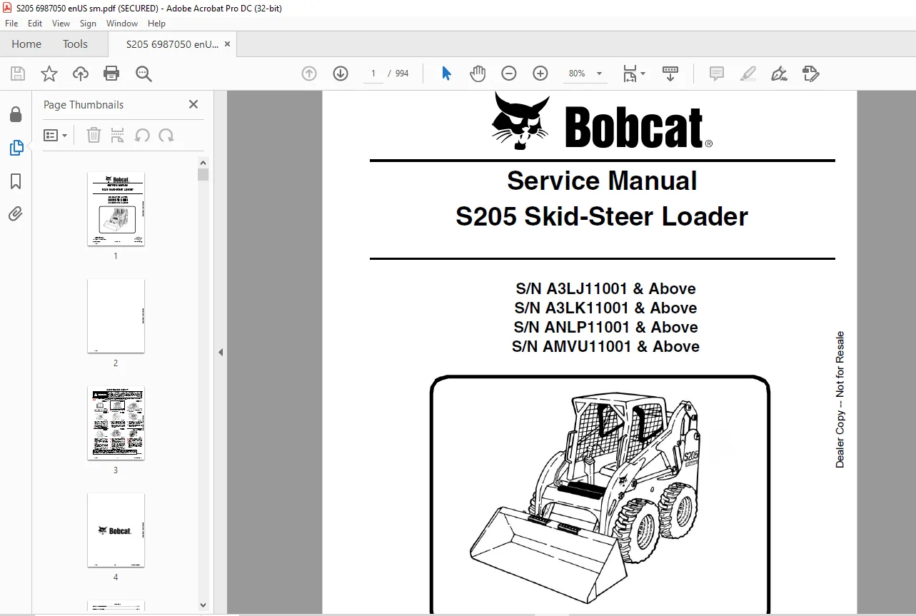
Bobcat S205 Skid-Steer Loader Service Manual 6987050 (07-14) – PDF DOWNLOAD
$34.95
Bobcat S205 Skid-Steer Loader Service Manual 6987050 (07-14) – PDF DOWNLOAD
Description
Bobcat S205 Skid-Steer Loader Service Manual 6987050 (07-14) – PDF DOWNLOAD
FILE DETAILS:
Bobcat S205 Skid-Steer Loader Service Manual 6987050 (07-14) – PDF DOWNLOAD
Language : English
Pages : 994
Downloadable : Yes
File Type : PDF
DESCRIPTION:
Bobcat S205 Skid-Steer Loader Service Manual 6987050 (07-14) – PDF DOWNLOAD
S/N A3LJ11001 & Above
S/N A3LK11001 & Above
S/N ANLP11001 & Above
S/N AMVU11001 & Above
FOREWORD:
This manual is for the Bobcat loader mechanic. It provides necessary servicing and adjustment procedures for the Bobcat loader and its component parts and systems. Refer to the Operation & Maintenance Manual for operating instructions, starting procedure, daily checks, etc.
A general inspection of the following items must be made after the loader has had service or repair:
TABLE OF CONTENTS:
Bobcat S205 Skid-Steer Loader Service Manual 6987050 (07-14) – PDF DOWNLOAD
MAINTENANCE SAFETY 3
CONTENTS 5
FOREWORD 7
FOREWORD 9
SAFETY INSTRUCTIONS 11
FIRE PREVENTION 13
Maintenance 13
Operation 13
Electrical 13
Hydraulic System 13
Fueling 13
Starting 13
Spark Arrester Exhaust System 13
Welding And Grinding 14
Fire Extinguishers 14
SERIAL NUMBER LOCATIONS 15
Loader Serial Number 15
Engine Serial Number 15
DELIVERY REPORT 16
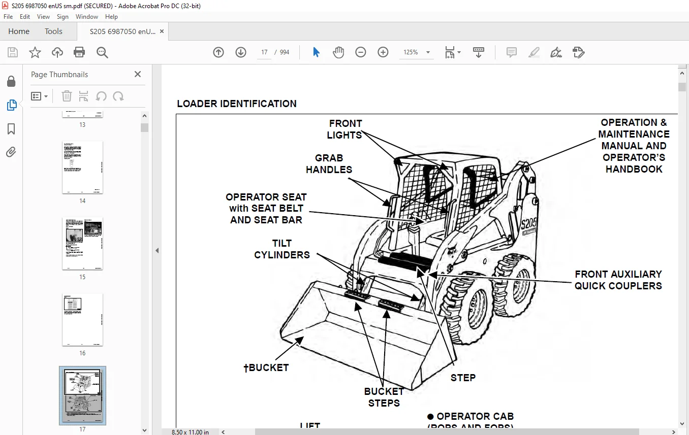
LOADER IDENTIFICATION 17
SAFETY & MAINTENANCE 19
LIFTING AND BLOCKING THE LOADER 23
Procedure 23
LIFT ARM SUPPORT DEVICE 25
Installing 25
Removing 26
OPERATOR CAB 27
Description 27
Raising 27
Lowering 28
Cab Door Sensor 30
Special Applications Kit 31
Special Applications Kit Inspection And Maintenance 31
TRANSPORTING THE LOADER ON A TRAILER 33
Loading And Unloading 33
Fastening 33
TOWING THE LOADER 35
Procedure 35
REMOTE START TOOL KIT-MEL1563 37
Remote Start Tool – MEL1563 37
Service Tool Harness Control – MEL1565 38
Service Tool Harness Communicator – MEL1566 39
Remote Start Procedure 40
REMOTE START TOOL (SERVICE TOOL) KIT – 7217666 43
Description 43
Remote Start Tool (Service Tool) – 7022042 44
Loader Service Tool Harness – 6689747 45
Computer Service Tool Harness – 6689746 46
Remote Start Procedure 47
SERVICE SCHEDULE 51
Chart 51
AIR CLEANER SERVICE 53
Replacing Filter Elements 53
ENGINE COOLING SYSTEM 55
Cleaning 55
Checking Level 56
Removing And Replacing Coolant 57
FUEL SYSTEM 59
Fuel Specifications 59
Biodiesel Blend Fuel 59
Filling The Fuel Tank 60
Fuel Filter 61
Removing Air From The Fuel System 61
ENGINE LUBRICATION SYSTEM 63
Checking And Adding Engine Oil 63
Engine Oil Chart 63
Removing And Replacing Oil And Filter 64
HYDRAULIC / HYDROSTATIC SYSTEM 65
Checking And Adding Fluid 65
Hydraulic / Hydrostatic Fluid Chart 65
Removing And Replacing Hydraulic Fluid 66
Removing And Replacing Hydraulic / Hydrostatic Filter 66
Removing And Replacing Hydraulic Case Drain Filters (Single Speed Loaders) 67
Removing And Replacing Hydraulic Case Drain Filters (Two-Speed Loaders) 68
Removing And Replacing Hydraulic Charge Filter 70
Breather Cap 71
FINAL DRIVE TRANSMISSION (CHAINCASE) 73
Checking And Adding Oil 73
Removing And Replacing Oil 74
BOB-TACH (HAND LEVER) 75
Inspection And Maintenance 75
BOB-TACH (POWER) 77
Inspection And Maintenance 77
LUBRICATING THE LOADER 79
Lubrication Locations 79
TIRE MAINTENANCE 81
Wheel Nuts 81
Rotating 81
Mounting 81
SPARK ARRESTER MUFFLER 83
Cleaning Procedure 83
PIVOT PINS 85
Inspection And Maintenance 85
LOADER STORAGE AND RETURN TO SERVICE 87
Storage 87
Return To Service 87
STOPPING THE ENGINE AND LEAVING THE LOADER 89
Procedure 89
EMERGENCY EXIT 91
Rear Window 91
Front Door 91
SEAT BELT 93
Inspection And Maintenance 93
HYDRAULIC SYSTEM 95
HYDRAULIC/HYDROSTATIC SCHEMATICS 101
HYDRAULIC SYSTEM INFORMATION 117
Glossary Of Hydraulic / Hydrostatic Symbols 117
Troubleshooting 121
CYLINDER (LIFT) 123
Testing 123
Removal And Installation 124
Parts Identification 126
Disassembly And Assembly 127
CYLINDER (TILT) 131
Testing 131
Removal And Installation 132
Rod End Pivot Pin Bushing And Seal Removal And Installation 133
Base End Pivot Pin Removal And Installation 134
Parts Identification 135
Disassembly And Assembly 136
CYLINDER (BOB-TACH) 139
Testing 139
Removal And Installation 140
Parts Identification 141
Disassembly And Assembly 142
MAIN RELIEF VALVE 145
Description 145
Testing 145
Adjusting 147
Removal And Installation 148
HYDRAULIC CONTROL VALVE (STANDARD) 149
Description 149
Removal And Installation 150
Identification Chart 155
Mount Bracket Removal And Installation 156
Lift Load Check Valve Removal And Installation 156
Load Check Valve Removal And Installation (Tilt And Auxiliary) 157
Anti-Cavitation Valve Removal And Installation (Lift, Rod End) 158
Port Relief / Anti-Cavitation Valve Removal And Installation (Lift, Base End) 159
Port Relief / Anti-Cavitation Valve Removal And Installation (Tilt, Base End) 159
Port Relief / Anti-Cavitation Valve Removal And Installation (Tilt, Rod End) 160
Port Relief Valve Removal And Installation 160
Plug Removal And Installation 161
Rubber Boot Removal And Installation 162
End Cap / Spool Lock Block Removal And Installation 163
Lift Spool And Detent Removal And Installation 164
Tilt Spool Removal And Installation 174
Auxiliary Spool Removal And Installation 176
Auxiliary Solenoid Removal And Installation (S/N A3LJ34999 & Below And A3LK34999 & Below) 178
Auxiliary Solenoid Removal And Installation (S/N A3LJ35001 & Above And A3LK35001 & Above) 179
Solenoid Removal And Installation 180
Lock Valve Removal And Installation 181
Lift Arm Bypass Orifice Removal And Installation 183
Main Relief Valve Removal And Installation 183
Check Valve Removal And Installation 184
HYDRAULIC CONTROL VALVE (ACS) OR (SJC) 185
Description 185
Removal And Installation 186
Actuator Removal And Installation (Out Of Loader) 190
Identification Chart 193
Mount Bracket Removal And Installation 194
Lift Load Check Valve Removal And Installation 194
Load Check Valve Removal And Installation (Tilt And Auxiliary) 195
Anti-Cavitation Valve Removal And Installation (Lift, Rod End) 196
Port Relief / Anti-Cavitation Valve Removal And Installation (Lift, Base End) 197
Port Relief / Anti-Cavitation Valve Removal And Installation (Tilt, Base End) 197
Port Relief / Anti-Cavitation Valve Removal And Installation (Tilt, Rod End) 198
Port Relief Valve Removal And Installation 198
Plug Removal And Installation 199
End Cap Block Removal And Installation 200
Lift Spool And Detent Removal And Installation 201
Tilt Spool Removal And Installation 206
Auxiliary Spool Removal And Installation 208
Auxiliary Solenoid Removal And Installation (S/N A3LJ34999 & Below And A3LK34999 & Below) 210
Auxiliary Solenoid Removal And Installation (S/N A3LJ35001 & Above And A3LK35001 & Above) 211
Solenoid Removal And Installation 212
Lock Valve Removal And Installation 213
Lift Arm Bypass Orifice Removal And Installation 215
Main Relief Valve Removal And Installation 215
Check Valve Removal And Installation 216
LIFT ARM BYPASS CONTROL VALVE 217
Description 217
Testing 217
Removal And Installation 218
Disassembly And Assembly 219
HYDRAULIC PUMP (STANDARD) 221
Description 221
Pump Test At Quick Couplers 221
Direct Pump Test (Standard Section) 222
Direct Pump Test (Charge Section) 224
Removal And Installation 226
Hydraulic Pump Startup 228
Parts Identification 229
Disassembly And Assembly 230
HYDRAULIC PUMP (STANDARD) (HIGH FLOW) 239
Description 239
Pump Test At Quick Couplers 239
Direct Pump Test (Standard Section) 240
Direct Pump Test (Charge Section) 242
Direct Pump Test (High Flow Section) 244
Removal And Installation 246
Hydraulic Pump Startup 248
Parts Identification 249
Disassembly And Assembly 250
HYDRAULIC PUMP (SJC) 263
Description 263
Pump Test At Quick Couplers 263
Direct Pump Test (Standard Section) 264
Direct Pump Test (Charge Section) 266
Removal And Installation 268
Hydraulic Pump Startup 270
Parts Identification 271
Disassembly And Assembly 272
HYDRAULIC PUMP (SJC) (HIGH FLOW) 281
Description 281
Pump Test At Quick Couplers 281
Direct Pump Test (Standard Section) 282
Direct Pump Test (Charge Section) 284
Direct Pump Test (High Flow Section) 286
Removal And Installation 288
Hydraulic Pump Startup 290
Parts Identification 291
Disassembly And Assembly 292
HYDRAULIC / HYDROSTATIC FILTERS 305
Description 305
Housing Removal And Installation 305
Charge Filter Housing Removal And Installation 307
HYDRAULIC FLUID RESERVOIR 309
Description 309
Removal And Installation 309
Hydraulic Fluid Screen 312
OIL COOLER 313
Description 313
Removal And Installation 313
BUCKET POSITION VALVE 315
Description 315
Solenoid Removal And Installation 315
Solenoid Testing 316
Removal And Installation 317
Disassembly And Assembly 319
REAR AUXILIARY DIVERTER VALVE 321
Description 321
Solenoid Testing 321
Removal And Installation 322
Disassembly And Assembly 325
BOB-TACH (POWER) BLOCK 331
Description 331
Removal And Installation 331
Disassembly And Assembly 333
FRONT AUXILIARY HYDRAULIC COUPLER BLOCK 339
Description 339
Removal And Installation 339
Disassembly And Assembly 340
HIGH FLOW VALVE 343
Description 343
High Flow Relief Valve Testing 343
High Flow Relief Valve Adjustment 345
Solenoid Testing 345
Removal And Installation 346
Disassembly And Assembly 348
HYDROSTATIC SYSTEM 351
HYDROSTATIC SYSTEM INFORMATION 353
Troubleshooting 353
Description 354
HYDROSTATIC DRIVE MOTOR 355
Description 355
Removal And Installation 356
Parts Identification 358
Disassembly And Assembly 359
HYDROSTATIC DRIVE MOTOR (TWO-SPEED) 365
Description 365
Removal And Installation (Left Side) 366
Removal And Installation (Right Side) 368
Parts Identification 372
Disassembly 373
Assembly 383
HYDROSTATIC MOTOR CARRIER (SINGLE AND TWO-SPEED WITH MANUAL CONTROLS) 395
Description 395
Shaft Seal Removal And Installation 396
Removal And Installation 398
Parts Identification 400
Disassembly And Assembly 401
HYDROSTATIC MOTOR CARRIER (SINGLE AND TWO-SPEED WITH SJC CONTROLS) 407
Description 407
Shaft Seal Removal And Installation 408
Removal And Installation 410
Parts Identification 412
Disassembly And Assembly 413
CHARGE PRESSURE 419
Description 419
Testing (S/N A3LJ29999 & Below And A3LK29999 & Below) 420
Sender Removal And Installation (S/N A3LJ29999 & Below And A3LK29999 & Below) 421
Testing (S/N A3LJ30001 & Above And A3LK30001 & Above) 422
Sender Removal And Installation (S/N A3LJ30001 & Above And A3LK30001 & Above) 423
Adjusting 424
HYDROSTATIC PUMP 427
Description 427
Replenishing / High Pressure Relief Valve Removal And Installation 427
Removal And Installation 428
Hydrostatic Pump Startup 429
Parts Identification (Left Half) 430
Parts Identification (Right Half) 431
Disassembly 432
Assembly 438
HYDROSTATIC PUMP (SJC) 445
Description 445
Hydraulic Controller Removal And Installation 446
Removal And Installation 448
Hydrostatic Pump Startup 450
Parts Identification 451
High Pressure Relief And Bypass Valve 452
Charge Relief Valve 453
Disassembly And Assembly 454
Mechanical Neutral Adjustment 469
Hydraulic Controller Neutral Adjustment 472
DRIVE BELT 475
Description 475
Shield Removal And Installation 475
Adjusting 476
Belt Removal And Installation 477
Tensioner Pulley Removal And Installation 478
Tensioner Pulley Parts Identification 479
Tensioner Pulley Disassembly 480
Tensioner Pulley Assembly 481
TWO-SPEED VALVE 483
Description 483
Valve Removal And Installation 484
Valve Disassembly And Assembly 486
CASE DRAIN FILTER 489
Description 489
Disassembly And Assembly 489
DRIVE SYSTEM 491
BRAKE (SINGLE SPEED) 493
Description 493
Disc Removal And Installation 493
BRAKE (TWO-SPEED) 495
Description 495
Disc Removal And Installation 496
Disc Disassembly And Assembly 497
DRIVE COMPONENTS 499
Description 499
Axle Seal Removal And Installation 500
Axle Sprocket And Bearings Removal And Installation 502
Chain Removal And Installation 507
CHAINCASE 509
Description 509
Front Cover Removal And Installation 509
Center Cover Removal And Installation 510
Rear Cover Removal And Installation 511
MAINFRAME 513
SEAT BAR 517
Description 517
Removal And Installation 517
Disassembly And Assembly 518
Compression Spring Disassembly And Assembly 519
OPERATOR CAB 521
Gas Cylinder Removal And Installation 521
Gas Cylinder Bracket Disassembly And Assembly 524
Removal And Installation 524
OPERATOR SEAT 527
Removal And Installation 527
Seat Belt Removal And Installation 528
OPERATOR SEAT (SUSPENSION) 529
Removal And Installation 529
Slide Rail Removal And Installation 530
Seat Belt Removal And Installation 530
Lower Cushion Removal And Installation 531
Back Cushion Removal And Installation 532
Shock Removal And Installation 532
3-Point Seat Belt Removal And Installation 533
BOB-TACH (HAND LEVER) 535
Description 535
Removal And Installation 535
Lever And Wedge Disassembly And Assembly 536
Pivot Pin Bushing And Seal Removal And Installation 538
BOB-TACH (POWER) 539
Description 539
Removal And Installation 539
Lever And Wedge Disassembly And Assembly 541
Pivot Pin Bushing And Seal Removal And Installation 542
LIFT ARMS 543
Stabilizer Bar Removal And Installation 543
Link Removal And Installation 544
Removal And Installation 545
REAR GRILLE 549
Removal And Installation 549
REAR DOOR (TAILGATE) 551
Removal And Installation 551
Striker Removal And Installation 552
Striker Disassembly And Assembly 552
Striker (Adjusting) 552
Latch Removal And Installation 553
FUEL TANK 555
Removal And Installation 555
Fuel Level Sender Removal And Installation 556
Fuel Fill Screen Removal And Installation 556
CONTROL PEDALS AND LINKAGES 557
Description 557
Pedal Removal And Installation 557
Linkage Removal And Installation 558
Pedal (Adjusting) 560
CONTROL PEDALS (ACS) 561
Description 561
Foot Sensor Removal And Installation 561
Foot Pedal Removal And Installation 562
Foot Pedal Linkage Disassembly And Assembly 562
CONTROL PANEL 563
Description 563
Removal And Installation 564
Shock Removal And Installation 567
Shaft Removal And Installation 567
Shaft Disassembly And Assembly 568
Linkage Removal And Installation 569
Pintle Arm Disassembly And Assembly 572
Linkage Neutral (Adjusting) 574
Linkage Travel (Adjusting) 578
CONTROL PANEL (SJC) 583
Description 583
Removal And Installation 583
CONTROL HANDLE / LEVER 585
Description 585
Lever Removal And Installation 585
Boot Removal And Installation 586
CONTROL HANDLE / LEVER (ACS) 587
Description 587
Handle Sensor Removal And Installation 587
Handle Removal And Installation 590
Handle Disassembly And Assembly 591
Lever Removal And Installation 592
Boot Removal And Installation 593
CONTROL HANDLE / LEVER (SJC) 595
Description 595
Joystick Testing 596
Joystick Removal And Installation 597
Joystick Mount Removal And Installation 598
ACCESS PANEL (INSIDE) 599
Removal And Installation (Left) 599
Removal And Installation (Right) 599
ACCESS PANEL (INSIDE) (SJC) 601
Removal And Installation (Left) 601
Removal And Installation (Right) 602
WINDOW (REAR) 605
Removal 605
Installation (Split Molding) 605
Installation (Continuous Molding) 607
WINDOW (TOP) 609
Removal And Installation 609
WINDOW (SIDE) 611
Removal And Installation 611
WINDOW (CAB DOOR) 613
Removal (Standard Window) 613
Installation (Standard Window) 614
Removal And Installation (Special Applications Window) 615
CAB DOOR 617
Description 617
Removal And Installation 617
Aligning 618
Adjusting 619
Checking Operation 619
ELECTRICAL SYSTEM & ANALYSIS 621
ELECTRICAL SCHEMATICS 625
ELECTRICAL SYSTEM INFORMATION 631
Glossary Of Electrical Symbols 631
Standard Cab Harness Connectors 634
Deluxe Cab Harness Connectors 635
Mainframe Harness Connectors 636
Description 637
Troubleshooting 638
Fuse And Relay Location / Identification 639
Solenoid Testing 640
BATTERY 641
Removal And Installation 641
Servicing 642
Using A Booster Battery (Jump Starting) 643
ALTERNATOR 645
Belt Adjustment 645
Belt Replacement 645
Charging System Inspection 646
Alternator Voltage Testing 647
Low Voltage Testing 647
High Voltage Testing 648
Removal And Installation 649
Parts Identification 650
STARTER 651
Testing 651
Removal And Installation 651
Parts Identification 652
INSTRUMENT PANELS 653
Left Panel 653
Standard Key Panel 655
Keyless Start Panel 655
Deluxe Instrumentation Panel 656
Side Panel 657
Front Panel 657
Front Panel Removal And Installation 658
Removal And Installation (Left And Right) 659
Key Switch Removal And Installation 660
Alarm Removal And Installation 660
LIGHTS 661
Front Removal And Installation 661
Rear Removal And Installation 662
Cab Light Removal And Installation 662
BOBCAT CONTROLLER (GATEWAY AND AUXILIARY) 663
Description 663
Connector Identification 664
Removal And Installation 670
BOBCAT CONTROLLER (ACS) 673
Description 673
Connector And Wire Identification 674
Removal And Installation 675
BOBCAT CONTROLLER (SJC) (DRIVE) 677
Description 677
Connector Identification 678
Removal And Installation 680
SPEED SENSORS (SJC) 681
Description 681
Testing 681
Removal And Installation 683
DIAGNOSTIC SERVICE CODES 685
Viewing Service Codes 685
Service Codes List 686
BOBCAT INTERLOCK CONTROL SYSTEM (BICS™) 691
Description 691
Inspecting The BICS™ (Engine STOPPED – Key ON) 692
Inspecting Deactivation Of The Auxiliary Hydraulics System (Engine STOPPED – Key ON) 692
Inspecting The Seat Bar Sensor (Engine RUNNING) 692
Inspecting The Traction Lock (Engine RUNNING) 692
Inspecting The Lift Arm Bypass Control 692
Inspecting Deactivation Of Lift And Tilt Functions (ACS And SJC) 692
Troubleshooting 693
SEAT BAR SENSOR 695
Description 695
Troubleshooting 695
Testing 696
Removal And Installation 697
Bobcat Interlock Control System (BICS™) Circuit Test 700
TRACTION LOCK 703
Description 703
Troubleshooting 703
Removal And Installation 704
Inspecting 708
CONTROL SYSTEM (ACS) 709
Description 709
Troubleshooting 710
Handle Sensor Connector Disassembly And Assembly 711
Switch Handle Removal 712
Switch Handle Installation 714
Actuator Connector Disassembly And Assembly 717
Handle Lock Solenoid Removal And Installation 718
Handle Lock Solenoid Disassembly And Assembly 718
Foot Sensor Disassembly And Assembly 719
Foot Lock Solenoid Removal And Installation 720
ELECTRICAL / HYDRAULIC CONTROLS 721
Identification Chart 721
Description 722
Identification Chart ACD Group 0 723
Identification Chart ACD Group 1 724
Identification Chart ACD Group 2 725
Identification Chart ACD Group 3 726
ELECTRICAL / HYDRAULIC CONTROLS (ACS) 727
Identification Chart 727
Description 728
Identification Chart ACD Group 0 729
Identification Chart ACD Group 1 730
Identification Chart ACD Group 2 731
Identification Chart ACD Group 3 732
ELECTRICAL / HYDRAULIC CONTROLS (SJC) 733
Identification Chart 733
Description 734
Identification Chart ACD Group 0 735
Identification Chart ACD Group 1 736
Identification Chart ACD Group 2 737
Identification Chart ACD Group 3 738
SERVICE PC (LAPTOP COMPUTER) 739
Connecting Remote Start Tool 739
Connecting Remote Start Tool (Service Tool) 739
CALIBRATION 741
Description 741
Actuator Testing 741
Lift And Tilt Calibration (SJC) 744
Hydrostatic Pump Calibration (SJC) 746
Lift And Tilt Calibration (ACS) 751
STEERING DRIFT COMPENSATION 753
Description 753
Operation 753
FLYWHEEL RPM SENSOR 755
Description 755
Adjusting 755
CONTROL PANEL SETUP 757
Right Panel Setup (Deluxe Instrumentation Panel) 757
Attachment Control Information (Deluxe Instrumentation Panel) 758
PASSWORD SETUP (DELUXE INSTRUMENTATION PANEL) 759
Password Description 759
Changing The Owner Password 759
Changing The User Passwords 760
Password Lockout Feature 760
PASSWORD SETUP (KEYLESS START PANEL) 761
Password Description 761
Changing The Owner Password 761
Password Lockout Feature 761
MAINTENANCE CLOCK 763
Description 763
Setup 764
Reset 767
BACK-UP ALARM SYSTEM 769
Description 769
Inspecting 769
Adjusting Switch Position 770
Troubleshooting (Standard And ACS) 771
Troubleshooting (Joystick) 772
Alarm Removal And Installation 773
Switch Removal And Installation 773
ENGINE SERVICE 775
ENGINE INFORMATION 779
Description 779
Specifications 780
Torque Values 784
Troubleshooting 784
Engine Removal And Installation 786
Engine Mount Replacement 793
Compression – Checking 794
ENGINE SPEED CONTROL 795
Removal And Installation 795
ENGINE SPEED CONTROL (SJC) 797
Removal And Installation 797
Disassembly And Assembly 799
MUFFLER 801
Removal And Installation 801
AIR CLEANER 803
Housing Removal And Installation 803
ENGINE COOLING SYSTEM 805
Radiator Removal And Installation 805
Hydraulic Fan Description (S/N A3LJ29999 & Below And A3LK29999 & Below) 808
Hydraulic Fan Disassembly And Assembly (S/N A3LJ29999 & Below And A3LK29999 & Below) 808
Blower Housing Removal And Installation (S/N A3LJ29999 & Below And A3LK29999 & Below) 809
Fan Removal And Installation (S/N A3LJ29999 & Below And A3LK29999 & Below) 811
Hydraulic Fan Motor Removal And Installation (S/N A3LJ29999 & Below And A3LK29999 & Below) 811
Hydraulic Fan Description (S/N A3LJ30001 & Above And A3LK30001 & Above) 812
Hydraulic Fan Disassembly And Assembly (S/N A3LJ30001 & Above And A3LK30001 & Above) 812
Blower Housing Removal And Installation (S/N A3LJ30001 & Above And A3LK30001 & Above) 814
Fan Removal And Installation (S/N A3LJ30001 & Above And A3LK30001 & Above) 816
Hydraulic Fan Motor Removal And Installation (S/N A3LJ30001 & Above And A3LK30001 & Above) 816
Water Pump Removal And Installation 817
Water Pump Disassembly And Assembly 817
Thermostat Housing Removal And Installation 818
Thermostat – Checking 819
LUBRICATION SYSTEM 821
Oil Pan Removal And Installation 821
Oil Pump Removal And Installation 821
Relief Valve – Testing 822
Oil Pump Inspection 822
Oil Filter Cooler Removal And Installation 823
Engine Oil Pressure – Testing 824
FUEL SYSTEM 825
Fuel Shutoff Solenoid – Checking 825
Fuel Shutoff Solenoid Removal And Installation 825
Fuel Injection Pump – Checking 826
Fuel Injection Pump Assembly Removal And Installation 827
Governor Housing Disassembly And Assembly 830
Governor Disassembly And Assembly 832
Fuel Camshaft Removal And Installation 833
Fuel Injection Pump Removal And Installation 835
Fuel Injection Pump – Timing 838
Fuel Injector Removal And Installation 840
Fuel Injector Nozzle Pressure – Checking 841
Nozzle Spray Condition 842
Valve Seat Tightness 842
CYLINDER HEAD 843
Glow Plugs – Testing 843
Glow Plugs Removal And Installation 843
Valve Clearance Adjustment 844
Valve Timing – Checking 845
Cylinder Head Removal And Installation 846
Cylinder Head Disassembly And Assembly 849
Cylinder Head – Servicing 849
Cylinder Head Top Clearance 850
Valve Guide – Checking 850
Valve Guide Removal And Installation 851
Reconditioning The Valve And Valve Seat 851
Valve Spring 853
Valve Tappets 854
Rocker Arm And Shaft – Checking 855
Bridge Arm And Bridge Arm Shaft – Checking 855
Bridge Arm Shaft Removal And Installation 856
Push Rod Alignment – Checking 857
CRANKSHAFT AND PISTONS 859
Piston And Connecting Rod Removal And Installation 859
Piston And Connecting Rod – Servicing 860
Cylinder Bore – Checking 864
Connecting Rod Alignment 865
Crankshaft Gear Removal And Installation 865
Crankshaft And Bearings Removal And Installation 866
Crankshaft And Bearings – Servicing 869
CAMSHAFT AND TIMING GEARS 873
Timing Gearcase Cover Removal 873
Timing Gearcase Cover Installation 874
Timing Gears Backlash – Checking 877
Idler Gear And Camshaft Removal And Installation 877
Camshaft – Servicing 878
Idler Gear And Shaft – Servicing 879
TURBOCHARGER 881
Description 881
Testing 881
Removal And Installation 882
FLYWHEEL AND HOUSING 883
Flywheel Removal And Installation 883
Ring Gear Removal And Installation 884
Housing Removal And Installation 885
EXHAUST GAS RECIRCULATION (EGR) SYSTEM 887
Description 887
Testing 888
Removal And Installation 891
Disassembly And Assembly 892
HEATING, VENTILATION AND AIR CONDITIONING (HVAC) 893
AIR CONDITIONING SYSTEM FLOW 896
Description 896
Chart 897
Components 898
Safety Equipment 901
REGULAR MAINTENANCE 903
Filters 903
Compressor Drive Belt Adjustment 903
Compressor Drive Belt Replacement 904
Condenser 904
Air Conditioning Lubrication 904
Air Conditioning Service Chart 905
Evaporator / Heater Coil 906
TROUBLESHOOTING 907
Blower Motor Does Not Operate 907
Blower Motor Operates Normally, But Air Flow Is Insufficient 907
Insufficient Cooling Although Air Flow And Compressor Operation Are Normal 907
The Compressor Does Not Operate At All, Or Operates Improperly 907
Gauge Pressure Related Troubleshooting 908
Troubleshooting Tree 910
Temperature / Pressure Chart 914
Poor A/C Performance 915
HVAC Repair And Leaks 916
Electrical System 917
Engine Coolant Bypassing The Heater Valve 924
Heater Valve Not Opening Or Closing 925
SYSTEM CHARGING AND RECLAMATION 927
Refrigerant Identification 927
Reclamation And Charging With Recovery / Charging Unit 928
Charging With A Manifold Gauge Set 930
COMPRESSOR 933
Removal And Installation 933
Oil 935
Oil Check 935
Clutch Disassembly And Assembly 937
CONDENSER 941
Removal And Installation 941
RECEIVER / DRIER 943
Receiver / Drier Removal And Installation 943
Pressure Relief Valve Removal And Installation 944
Pressure Switch Removal And Installation 945
Schraeder® Valve Removal And Installation 946
EVAPORATOR / HEATER UNIT 947
Removal And Installation 947
THERMOSTAT 949
Description 949
Removal And Installation 950
EXPANSION VALVE 951
Removal And Installation 951
EVAPORATOR COIL 953
Removal And Installation 953
HEATER COIL 955
Removal And Installation With A/C 955
Removal And Installation Without A/C 957
BLOWER FAN 959
Removal And Installation 959
Disassembly And Assembly 960
Connector Identification 962
HEATER VALVE 963
Removal And Installation 963
Disassembly And Assembly 964
SPECIFICATIONS 965
(S205) LOADER SPECIFICATIONS 967
Machine Dimensions 967
Performance 968
Engine 968
Drive System 968
Controls 969
Hydraulic System 969
Electrical 970
Capacities 970
Tires 970
TORQUE SPECIFICATIONS FOR BOLTS 971
Torque For General SAE Bolts 971
Torque For General Metric Bolts 972
HYDRAULIC CONNECTION SPECIFICATIONS 973
O-ring Face Seal Connection 973
Straight Thread O-ring Fitting 974
Tubelines And Hoses 974
Flare Fitting 975
Port Seal Fitting 976
HYDRAULIC / HYDROSTATIC FLUID SPECIFICATIONS 977
Specifications 977
CONVERSIONS 979
Decimal And Millimeter Equivalent Chart 979
U S To Metric Conversion Chart 979
SERVICE TOOLS REQUIRED 981
Remote Start Tools 981
Hydraulic Tools 982
Mainframe And Drive Tools 984
Electrical Tools 985
Engine Tools 985
HVAC Tools 990
ALPHABETICAL INDEX 991
IMAGES PREVIEW OF THE MANUAL:
Contact us: [email protected]
PLEASE NOTE:
- This is the same manual used by the dealers to diagnose and troubleshoot your vehicle
- You will be directed to the download page as soon as the purchase is completed. The whole payment and downloading process will take anywhere between 2-5 minutes
- Need any other service / repair / parts manual, please feel free to contact [email protected] . We still have 50,000 manuals unlisted
S.V