Service Manual for Bobcat S220 Skid-Steer Loader 6986679 (3-09) PDF
$34.95
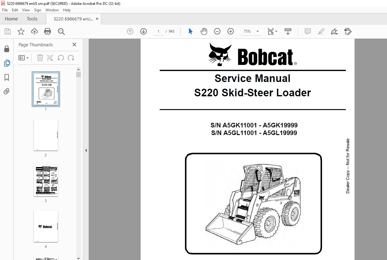
Bobcat S220 Skid-Steer Loader Service Manual 6986679 (3-09) – PDF DOWNLOAD
S/N A5GK11001 – A5GK19999
S/N A5GL11001 – A5GL19999
Description
Bobcat S220 Skid-Steer Loader Service Manual 6986679 (3-09) – PDF DOWNLOAD
FILE DETAILS:
Bobcat S220 Skid-Steer Loader Service Manual 6986679 (3-09) – PDF DOWNLOAD
Language : English
Pages : 943
Downloadable : Yes
File Type : PDF
DESCRIPTION:
Bobcat S220 Skid-Steer Loader Service Manual 6986679 (3-09) – PDF DOWNLOAD
S/N A5GK11001 – A5GK19999
S/N A5GL11001 – A5GL19999
FOREWORD:
This manual is for the Bobcat loader mechanic. It provides necessary servicing and adjustment procedures for the Bobcat loader and its component parts and systems. Refer to the Operation & Maintenance Manual for operating instructions, starting procedure, daily checks, etc.
A general inspection of the following items must be made after the loader has had service or repair:
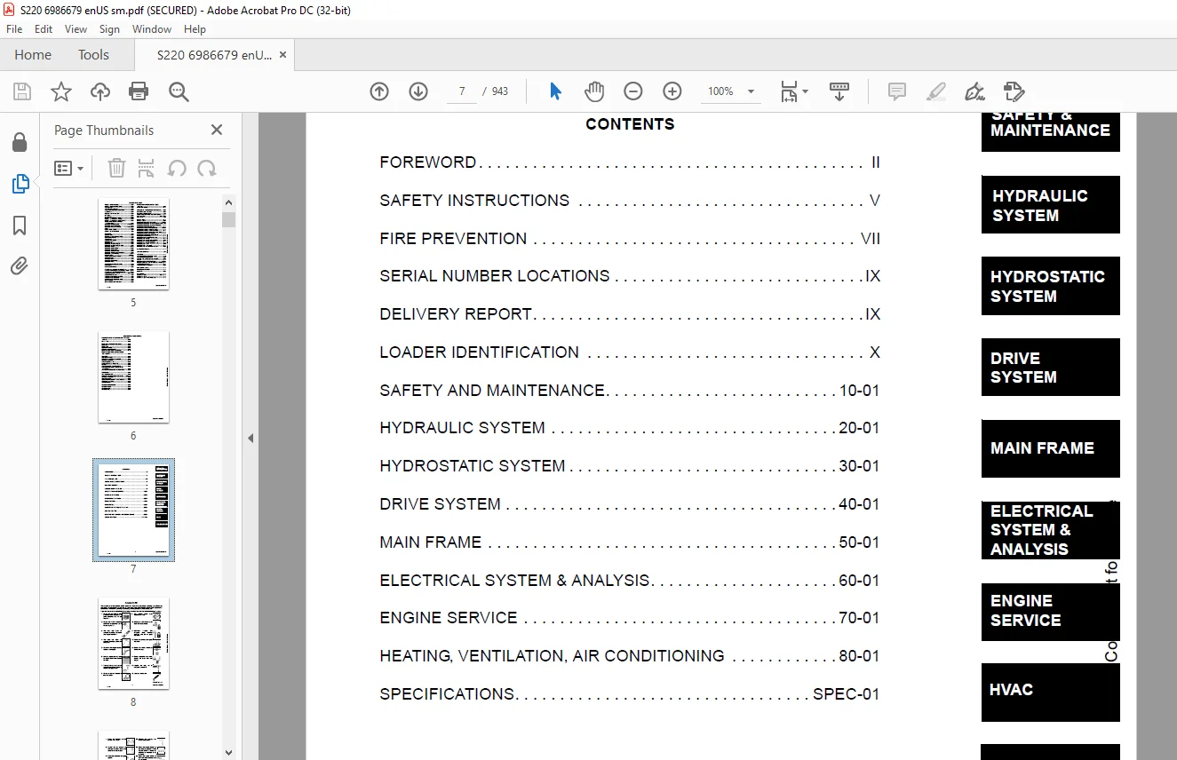
TABLE OF CONTENTS:
Bobcat S220 Skid-Steer Loader Service Manual 6986679 (3-09) – PDF DOWNLOAD
MAINTENANCE SAFETY 3
ALPHABETICAL INDEX 5
CONTENTS 7
FOREWORD 8
SAFETY INSTRUCTIONS 11
FIRE PREVENTION 13
Maintenance 13
Operation 13
Electrical 13
Hydraulic System 13
Fueling 13
Starting 13
Spark Arrestor Exhaust System 13
Welding And Grinding 14
Fire Extinguishers 14
SERIAL NUMBER LOCATIONS 15
Loader Serial Number 15
Engine Serial Number 15
DELIVERY REPORT 15
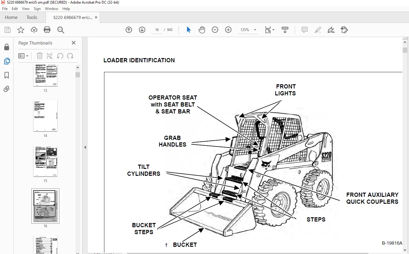
LOADER IDENTIFICATION 16
SAFETY AND MAINTENANCE 17
LIFTING AND BLOCKING THE LOADER 21
Procedure 21
LIFT ARM SUPPORT DEVICE 23
Installing 23
Removing 24
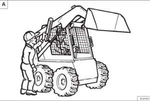
OPERATOR CAB 25
Description 25
Raising 26
Lowering 27
Cab Door Sensor 28
Special Applications Kit Inspection And Maintenance 28
TRANSPORTING LOADER ON A TRAILER 29
Loading And Unloading 29
Fastening 29
TOWING THE LOADER 31
Procedure 31
REMOTE START TOOL KIT-MEL1563 33
Remote Start Tool – MEL1563 33
Service Tool Harness Control – MEL1565 34
Service Tool Harness Communicator – MEL1566 35
Remote Start Procedure 36
REMOTE START TOOL (SERVICE TOOL) KIT – 6689779 39
Description 39
Remote Start Tool (Service Tool) – 6689778 40
Loader Service Tool Harness – 6689747 41
Computer Service Tool Harness – 6689746 42
Remote Start Procedure 43
SERVICE SCHEDULE 47
Chart 47
AIR CLEANER SERVICE 49
Replacing Filter Elements 49
ENGINE COOLING SYSTEM 51
Cleaning 51
Removing And Replacing Coolant 52
Checking Level 52
FUEL SYSTEM 53
Fuel Specifications 53
Biodiesel Blend Fuel 53
Filling The Fuel Tank 54
Fuel Filter 55
Removing Air From The Fuel System 55
ENGINE LUBRICATION SYSTEM 57
Checking And Adding Engine Oil 57
Engine Oil Chart 57
Removing And Replacing Oil And Filter 58
HYDRAULIC / HYDROSTATIC SYSTEM 59
Checking And Adding Fluid 59
Hydraulic / Hydrostatic Fluid Chart 59
Removing And Replacing Hydraulic Fluid 60
Removing And Replacing Hydraulic / Hydrostatic Filter 61
Removing And Replacing Case Drain Filters 62
Removing And Replacing Hydraulic Charge Filter 63
Breather Cap 64
FINAL DRIVE TRANSMISSION (CHAINCASE) 65
Checking And Adding Oil 65
Removing And Replacing Oil 65
BOB-TACH (HAND LEVER) 67
Inspection And Maintenance 67
BOB-TACH (POWER – OPTION) 69
Inspection And Maintenance 69
LUBRICATING THE LOADER 71
Lubrication Locations 71
TIRE MAINTENANCE 73
Wheel Nuts 73
Rotating 73
Mounting 74
SPARK ARRESTOR MUFFLER 75
Cleaning Procedure 75
PIVOT PINS 77
Inspection And Maintenance 77
LOADER STORAGE AND RETURN TO SERVICE 79
Storage 79
Return to Service 79
STOPPING THE ENGINE AND LEAVING THE LOADER 81
Procedure 81
Emergency Exit 82
HYDRAULIC SYSTEM 83
HYDRAULIC / HYDROSTATIC SCHEMATICS 89
HYDRAULIC SYSTEM INFORMATION 105
Glossary Of Hydraulic / Hydrostatic Symbols 105
Troubleshooting 109
CYLINDER (LIFT) 111
Testing 111
Removal And Installation 112
Parts Identification 114
Disassembly 115
Assembly 117
CYLINDER (TILT) 119
Testing 119
Removal And Installation 120
Base End Pivot Pin Removal And Installation 122
Parts Identification 123
Disassembly 124
Assembly 126
CYLINDER (BOB-TACH) 129
Testing 129
Removal And Installation 130
Parts Identification 131
Disassembly 132
Assembly 133
MAIN RELIEF VALVE 137
Description 137
Testing 138
Adjusting 140
Removal And Installation 141
HYDRAULIC CONTROL VALVE (STANDARD) 143
Description 143
Removal And Installation 144
Identification Chart 148
Mount Bracket Removal And Installation 149
Lift Load Check Valve Removal And Installation 149
Load Check Valve Removal And Installation (Tilt & Auxiliary) 150
Anti-Cavitation Valve Removal And Installation (Lift, Rod End) 150
Port Relief / Anti-Cavitation Valve Removal And Installation (Lift, Base End) 151
Port Relief / Anti-Cavitation Valve Removal And Installation (Tilt, Base End) 152
Port Relief / Anti-Cavitation Valve Removal And Installation (Tilt, Rod End) 152
Port Relief Valve Removal And Installation 153
Plug Removal And Installation 154
Rubber Boot Removal and Installation 155
End Cap Block Removal and Installation 156
Lift Spool And Detent Removal And Installation 157
Tilt Spool Removal And Installation 167
Auxiliary Spool Removal And Installation 169
Auxiliary Solenoid Removal And Installation 171
Solenoid Removal And Installation 172
Lock Valve Removal And Installation 173
Lift Arm Bypass Orifice Removal And Installation 175
Main Relief Valve Removal And Installation 175
Check Valve Removal And Installation 176
HYDRAULIC CONTROL VALVE (ACS) OR (SJC) 177
Description 177
Removal And Installation 178
Actuator Removal And Installation (In Loader) 182
Actuator Removal And Installation (Out Of Loader) 184
Identification Chart 187
Mount Bracket Removal And Installation 188
Lift Load Check Valve Removal And Installation 188
Load Check Valve Removal And Installation (Tilt & Auxiliary) 189
Anti-Cavitation Valve Removal And Installation (Lift, Rod End) 189
Port Relief / Anti-Cavitation Valve Removal And Installation (Lift, Base End) 190
Port Relief / Anti-Cavitation Valve Removal And Installation (Tilt, Base End) 191
Port Relief / Anti-Cavitation Valve Removal And Installation (Tilt, Rod End) 191
Port Relief Valve Removal And Installation 192
Plug Removal And Installation 193
End Cap Block Removal And Installation 194
Lift Spool And Detent Removal And Installation 195
Tilt Spool Removal And Installation 200
Auxiliary Spool Removal And Installation 202
Auxiliary Solenoid Removal And Installation 204
Solenoid Removal And Installation 205
Lock Valve Removal And Installation 206
Lift Arm Bypass Orifice Removal And Installation 208
Main Relief Valve Removal And Installation 208
Check Valve Removal And Installation 209
LIFT ARM BYPASS CONTROL VALVE 211
Description 211
Testing 211
Removal And Installation 212
Disassembly And Assembly 213
HYDRAULIC PUMP (STANDARD) 215
Description 215
Pump Test at Quick Couplers 216
Direct Pump Test (Standard Section) 217
Direct Pump Test (Charge Section) 219
Removal And Installation 223
Hydraulic Pump Start Up 225
Parts Identification 226
Disassembly And Assembly 227
HYDRAULIC PUMP (STANDARD) (HIGH FLOW) 229
Description 229
Pump Test At Quick Couplers 230
Direct Pump Test (Standard Section) 231
Direct Pump Test (Charge Section) 233
Direct Pump Test (High Flow Section) 237
High Flow Relief Valve Adjustment 239
High Flow Relief Valve Removal And Installation 242
Solenoid Removal And Installation 243
Removal And Installation 244
Hydraulic Pump Start Up 246
Parts Identification 248
Disassembly And Assembly 249
HYDRAULIC PUMP (SJC) 251
Description 251
Pump Test At Quick Couplers 252
Direct Pump Test (Standard Section) 253
Direct Pump Test (Charge Section) 255
Removal And Installation 259
Hydraulic Pump Start Up 261
Parts Identification 262
Disassembly And Assembly 263
HYDRAULIC PUMP (SJC) (HIGH FLOW) 265
Description 265
Pump Test At Quick Couplers 266
Direct Pump Test (Standard Section) 267
Direct Pump Test (Charge Section) 269
Direct Pump Test (High Flow Section) 273
High Flow Relief Valve Adjustment 275
High Flow Relief Valve Removal And Installation 278
Solenoid Removal And Installation 279
Removal And Installation 280
Hydraulic Pump Start Up 282
Parts Identification 284
Disassembly And Assembly 285
HYDRAULIC/HYDROSTATIC FILTERS 287
Description 287
Housing Removal And Installation 287
HYDRAULIC FLUID RESERVOIR 289
Description 289
Removal And Installation 289
Hydraulic Fluid Screen 292
OIL COOLER 293
Description 293
Removal And Installation 293
BUCKET POSITION VALVE 295
Description 295
Solenoid Removal And Installation 296
Solenoid Testing 297
Removal And Installation 297
Disassembly And Assembly 298
REAR AUXILIARY DIVERTER VALVE 301
Description 301
Solenoid Testing 301
Removal And Installation 302
Disassembly And Assembly 304
BOB-TACH (POWER) BLOCK 311
Description 311
Removal And Installation 311
Disassembly And Assembly 313
FRONT AUXILIARY HYDRAULIC COUPLER BLOCK 317
Description 317
Removal and Installation 317
Disassembly And Assembly 318
HYDROSTATIC SYSTEM 321
HYDROSTATIC SYSTEM INFORMATION 323
Troubleshooting 323
Description 324
HYDROSTATIC MOTOR 325
Description 325
Removal And Installation 326
Parts Identification 328
Disassembly And Assembly 329
HYDROSTATIC MOTOR (TWO-SPEED) 333
Description 333
Removal And Installation 334
Parts Identification 337
Disassembly 339
Assembly 345
HYDROSTATIC MOTOR CARRIER 349
Description 349
Removal And Installation 350
Parts Identification 351
Disassembly 352
Assembly 353
HYDROSTATIC MOTOR CARRIER (SJC) 355
Description 355
Removal And Installation 356
Parts Identification 357
Disassembly 358
Assembly 360
CHARGE PRESSURE 363
Description 363
Testing 364
Sender Removal And Installation 366
Adjusting 367
HYDROSTATIC PUMP 369
Description 369
Removal And Installation 370
Hydrostatic Pump Startup 372
Replenishing / High Pressure Relief Valve Removal And Installation 373
Parts Identification (Left Half) 374
Parts Identification (Right Half) 375
Disassembly 376
Assembly 383
HYDROSTATIC PUMP (SJC) 389
Description 389
Hydraulic Controller Removal And Installation 390
Removal And Installation 392
Hydrostatic Pump Startup 394
Parts Identification 395
High Pressure Relief And ByPass Valve 396
Charge Relief Valve 397
Disassembly And Assembly 398
Mechanical Neutral Adjustment 415
Hydraulic Controller Neutral Adjustment 418
DRIVE BELT 421
Description 421
Shield Removal And Installation 421
Adjusting 422
Belt Removal And Installation 422
Tensioner Pulley Removal And Installation 423
Tensioner Pulley Disassembly And Assembly 424
Tensioner Pulley Tension Spring Removal And Installation 425
Tensioner Pulley Tension Spring Disassembly And Assembly 425
CASE DRAIN FILTER 427
Description 427
Disassembly And Assembly 427
DRIVE SYSTEM 429
BRAKE 431
Description 431
Disc Removal And Installation 432
BRAKE (TWO-SPEED) 435
Description 435
Block Removal And Installation 436
Block Disassembly And Assembly 438
DRIVE COMPONENTS 443
Description 443
Axle Seal Removal And Installation 444
Axle, Sprocket And Bearings Removal And Installation 446
Chain Removal And Installation 451
Description 452
Axle Seal Removal And Installation 453
Axle, Sprocket And Bearings Removal And Installation 455
Chain Removal And Installation 460
CHAINCASE 463
Description 463
Front Cover Removal And Installation 463
Center Cover Removal And Installation 464
Rear Cover Removal And Installation 465
MAIN FRAME 467
SEAT BAR 471
Description 471
Removal And Installation 471
Disassembly And Assembly 473
Compression Spring Disassembly And Assembly 474
OPERATOR CAB 475
Gas Cylinder Removal And Installation 475
Gas Cylinder Bracket Disassembly And Assembly 477
Removal And Installation 478
OPERATOR SEAT 481
Removal And Installation 481
Seat Belt Removal And Installation 481
OPERATOR SEAT (SUSPENSION) 483
Removal And Installation 483
Slide Rail Removal And Installation 484
Seat Belt Removal And Installation 484
Cushion Removal And Installation 485
Back Removal And Installation 486
Shock Removal And Installation 486
3-Point Seat Belt Removal And Installation 487
BOB-TACH (HAND LEVER) 489
Description 489
Removal And Installation 489
Lever And Wedge Disassembly And Assembly 492
Pivot Pin Bushing And Seal Removal And Installation 493
BOB-TACH (POWER – OPTION) 495
Description 495
Removal And Installation 495
Lever And Wedge Disassembly And Assembly 498
Pivot Pin Bushing And Seal Removal And Installation 500
LIFT ARMS 501
Removal And Installation 501
REAR GRILL 505
Removal And Installation 505
REAR DOOR 507
Removal And Installation 507
Striker Removal And Installation 508
Striker Disassembly And Assembly 508
Striker (Adjusting) 509
Latch Removal And Installation 510
FUEL TANK 511
Removal And Installation 511
Fuel Level Sender Removal And Installation 514
Fuel Fill Screen Removal And Installation 514
CONTROL PEDALS AND LINKAGES 515
Description 515
Pedal Removal And Installation 516
Linkage Removal And Installation 517
Pedal (Adjusting) 518
CONTROL PEDALS (ACS) 519
Description 519
Foot Sensor Removal And Installation 520
Foot Pedal Removal And Installation 521
Foot Pedal Linkage Disassembly And Assembly 522
CONTROL PANEL 523
Description 523
Removal And Installation 524
Shock Removal And Installation 526
Shaft Removal And Installation 527
Linkage Removal And Installation 528
Pintle Arm Disassembly and Assembly 532
Linkage Neutral (Adjusting) 533
Linkage Travel (Adjusting) 537
CONTROL PANEL (SJC) 541
Description 541
Removal And Installation 542
CONTROL HANDLE / LEVER 545
Description 545
Lever Removal And Installation 545
Boot Removal And Installation 546
CONTROL HANDLE / LEVER (ACS) 547
Description 547
Handle Sensor Removal And Installation 547
Handle Removal And Installation 550
Handle Disassembly And Assembly 551
Lever Removal And Installation 552
Boot Removal And Installation 553
JOYSTICK CONTROL 555
Description 555
Testing 556
Removal And Installation 557
Joystick Mount Removal And Installation 558
ACCESS PANEL (INSIDE) 559
Removal And Installation (Left) 559
Removal And Installation (Right) 559
ACCESS PANEL (INSIDE) (SJC) 561
Removal And Installation (Left) 561
Removal And Installation (Right) 562
WINDOW (REAR) 565
Removal 565
Installation 565
WINDOW (TOP) 567
Removal And Installation 567
WINDOW (SIDE) 569
Removal And Installation 569
WINDOW (FRONT DOOR) 571
Removal (Standard Window) 571
Installation (Standard Window) 572
Removal And Installation (Special Applications Window) 574
CAB DOOR 575
Description 575
Removal And Installation 575
Aligning 576
Adjusting 577
Checking Operation 577
ELECTRICAL SYSTEM & ANALYSIS 579
ELECTRICAL SCHEMATICS 583
ELECTRICAL SYSTEM INFORMATION 590
Glossary Of Electrical Symbols 590
Cab Harness Connectors 593
Mainframe Harness Connectors 594
Description 596
Troubleshooting 598
Fuse And Relay Location / Identification 599
Solenoid Testing 600
BATTERY 602
Removal And Installation 602
Servicing 603
Using A Booster Battery (Jump Starting) 604
ALTERNATOR 606
Belt Adjustment 606
Charging System Inspection 607
Alternator Voltage Testing 608
Low Voltage Testing 608
High Voltage Testing 609
Removal And Installation 610
Parts Identification 611
STARTER 612
Testing 612
Removal And Installation 613
Parts Identification 614
INSTRUMENT PANELS 616
Left Panel 616
Right Panel (Key Switch) 617
Right Panel (Keyless) 618
Side And Front Panels 620
Removal And Installation (Left And Right) 621
Bulb Removal And Installation (Left Only) 624
Key Switch Removal And Installation 625
Alarm Removal And Installation 626
Front Panel Removal And Installation 626
LIGHTS 628
Front Removal And Installation 628
Rear Removal And Installation 629
Cab Light Removal And Installation 629
BOBCAT CONTROLLER (MAIN) 630
Description 630
Connector Identification 631
Removal And Installation 633
BOBCAT CONTROLLER (ACS) 634
Description 634
Connector And Wire Identification 635
Removal And Installation 636
BOBCAT CONTROLLER (SJC) (DRIVE) 638
Description 638
Connector Identification 639
Removal And Installation 641
SPEED SENSOR (SJC) 642
Description 642
Testing 643
Removal And Installation 644
DIAGNOSTIC SERVICE CODES 646
Viewing Service Codes (Key Switch) 646
Viewing Service Codes (Keyless) 646
Service Codes List 647
BOBCAT INTERLOCK CONTROL SYSTEM (BICS) 652
Description 652
Inspecting The BICS Controller (Engine STOPPED – Key ON) 653
Inspecting Deactivation Of The Auxiliary Hydraulics System (Engine STOPPED – Key ON) 653
Inspecting The Seat Bar Sensor (Engine RUNNING) 653
Inspecting The Traction Lock (Engine RUNNING) 653
Inspecting The Lift Arm Bypass Control 653
Inspecting Deactivation Of Lift And Tilt Functions (ACS And SJC) 653
Troubleshooting 654
Troubleshooting Chart 655
SEAT BAR SENSOR 656
Description 656
Troubleshooting 657
Testing 658
Removal And Installation 659
Bobcat Interlock Control System (BICS) Circuit Test 660
TRACTION LOCK 662
Description 662
Troubleshooting 663
Removal And Installation (Single Speed) 664
Inspecting (Single And Two Speed) 668
CONTROL SYSTEM (ACS) 670
Description 670
Troubleshooting Chart 671
Handle Sensor Connector Disassembly And Assembly 672
Switch Handle Removal 673
Switch Handle Installation 675
Actuator Connector Disassembly And Assembly 678
Handle Lock Solenoid Removal And Installation 679
Handle Lock Solenoid Disassembly And Assembly 680
Foot Sensor Disassembly And Assembly 680
Foot Lock Solenoid Removal And Installation 681
ELECTRICAL / HYDRAULIC CONTROLS 682
Identification Chart 682
ELECTRICAL / HYDRAULIC CONTROLS (SJC) 684
Identification Chart 684
SERVICE PC (LAPTOP COMPUTER) 688
Connecting Remote Start Tool 688
Connecting Remote Start Tool (Service Tool) 688
CALIBRATION 690
Description 690
Actuator Testing 690
Lift And Tilt Calibration (ACS) 692
Lift And Tilt Calibration (SJC) 694
Hydrostatic Pump Calibration (SJC) 696
STEERING DRIFT COMPENSATION 702
Description 702
Selecting And Adjusting 702
Exiting And Saving 703
FLYWHEEL RPM SENSOR 704
Description 704
Adjustment 705
CONTROL PANEL SETUP 706
Right Panel Setup (Keyless) 706
Attachment Control Information (Keyless) 707
PASSWORD SETUP (IF EQUIPPED WITH KEYLESS START) 708
Password Description 708
Changing The Owner And User Passwords 709
Password Lockout Feature 710
MAINTENANCE CLOCK 712
Description 712
Setup 713
Reset 717
BACK-UP ALARM SYSTEM 718
Description 718
Inspecting 718
Adjusting Switch Position 719
Troubleshooting (Standard And ACS) 720
Troubleshooting (Joystick) 721
Alarm Removal And Installation 722
Switch Removal And Installation 722
ENGINE SERVICE 724
ENGINE INFORMATION 728
Description 728
Specifications 729
Torque Values 734
Troubleshooting 735
Engine Removal And Installation 737
Engine Mount Replacement 743
Compression – Checking 744
ENGINE SPEED CONTROL 746
Removal And Installation 746
Cable Removal And Installation 746
ENGINE SPEED CONTROL (SJC) 748
Removal And Installation 748
Disassembly And Assembly 750
Speed Control Cable Removal And Installation 751
MUFFLER 752
Removal And Installation 752
AIR CLEANER 754
Housing Removal And Installation 754
ENGINE COOLING SYSTEM 756
Radiator Removal And Installation 756
Radiator Mount Removal And Installation 758
Hydraulic Fan Motor Description 759
Axial Fan Housing Removal And Installation 759
Axial Fan Removal And Installation 762
Hydraulic Fan Motor Removal And Installation 763
Hydraulic Fan Motor Disassembly And Assembly 764
Water Pump Removal And Installation 765
Water Pump Disassembly And Assembly 766
Thermostat Housing Removal And Installation 766
LUBRICATION SYSTEM 768
Oil Pan Removal And Installation 768
Oil Pump Removal And Installation 769
Oil Pump Inspection 769
Oil Filter Cooler Removal And Installation 771
Engine Oil Pressure – Testing 772
FUEL SYSTEM 774
Fuel Shutoff Solenoid – Checking 774
Fuel Shutoff Solenoid – Removal And Installation 774
Fuel Injection Pump Assembly Removal 775
Fuel Injection Pump Assembly Installation 779
Governor Housing Disassembly And Assembly 781
Governor Disassembly And Assembly 783
Fuel Camshaft Removal And Installation 785
Fuel Injection Pump Removal 787
Injection Pump Timing 794
Fuel Injector Removal And Installation 797
Fuel Injector Nozzle Pressure – Checking 798
Nozzle Spraying Condition 799
Valve Seat Tightness 799
CYLINDER HEAD 802
Intake Air Heater – Testing 802
Intake Air Heater Removal And Installation 802
Valve Clearance Adjustment 803
Cylinder Head Removal And Installation 805
Cylinder Head Top Clearance 807
Cylinder Head Disassembly And Assembly 808
Cylinder Head – Servicing 808
Valve Guide – Checking 809
Reconditioning The Valve And Valve Seat 811
Valve Spring 813
Valve Tappets 814
Rocker Arm And Shaft – Checking 815
Push Rod Alignment – Checking 815
CRANKSHAFT AND PISTONS 816
Piston And Connecting Rod Removal And Installation 816
Piston And Connecting Rod – Servicing 818
Cylinder Bore Checking 822
Connecting Rod Alignment 823
Crankshaft Gear Removal And Installation 823
Crankshaft And Bearings Removal 824
Crankshaft And Bearings Installation 826
Crankshaft And Bearings – Servicing 828
CAMSHAFT AND TIMING GEArS 834
Timing Gearcase Cover Removal And Installation 834
Timing Gears Backlash – Checking 835
Idler Gear And Camshaft Removal and Installation 835
Camshaft – Servicing 836
Idler Gear And Shaft – Servicing 838
TURBOCHARGER 840
Description 840
Testing 840
Removal And Installation 841
FLYWHEEL AND HOUSING 842
Flywheel Removal And Installation 842
Ring Gear Removal And Installation 842
Housing Removal And Installation 843
EXHAUST GAS RECIRCULATION (EGR) SYSTEM 844
Description 844
Testing 845
Removal And Installation 848
HEATING, VENTILATION, AIR CONDITIONING 850
AIR CONDITIONING SYSTEM FLOW 853
Description 853
Chart 854
Components 855
Safety Equipment 858
REGULAR MAINTENANCE 860
Filter Elements Removal And Installation 860
Compressor Drive Belt Inspection 860
Condenser 861
Air Conditioning Service Chart 862
A/C Evaporator Coil & Heater Coil 863
TROUBLESHOOTING 864
Blower Motor Does Not Operate 864
Blower Motor Operates Normally, But Air Flow Is Insufficient 864
Insufficient Cooling Although Air Flow And Compressor Operation Are Normal 864
The Compressor Does Not Operate At All, Or Operates Improperly 864
Gauge Pressure Related Troubleshooting 865
Troubleshooting Tree 867
Temperature / Pressure Chart 871
Poor A/C Performance 873
HVAC Repair And Leaks 874
Electrical System 875
Engine Coolant By Passing The Heater Valve 882
Heater Valve Not Opening Or Closing 883
SYSTEM CHARGING AND RECLAMATION 884
Refrigerant Identification 884
Reclamation And Charging With Recovery / Charging Unit 885
Charging With A Manifold Gauge Set 887
COMPRESSOR 890
Belt Adjustment 890
Removal And Installation 890
Oil 891
Oil Check 892
Clutch Disassembly And Assembly 893
CONDENSER 898
Removal And Installation 898
RECEIVER / DRIER 900
Receiver / Drier Removal And Installation 900
Pressure Relief Valve Removal And Installation 901
Pressure Switch Removal And Installation 901
Schraeder Valve Removal And Installation 902
EVAPORATOR / HEATER UNIT 904
Removal And Installation 904
THERMOSTAT 906
Removal And Installation 906
EXPANSION VALVE 908
Removal And Installation 908
EVAPORATOR 910
Removal And Installation 910
HEATER COIL 912
Removal And Installation With A/C 912
Removal And Installation Without A/C 914
BLOWER FAN 916
Removal And Installation 916
Disassembly And Assembly 917
Connector Identification 919
HEATER VALVE 920
Removal and Installation 920
Disassembly And Assembly 921
SPECIFICATIONS 922
(S220) LOADER SPECIFICATIONS 924
Dimensions 924
Performance 925
Controls 925
Engine 925
Hydraulic System 926
Electrical 926
Drive System 927
Capacities 927
Tires 927
TORQUE SPECIFICATIONS FOR BOLTS 928
Torque For General SAE Bolts 928
Torque For General Metric Bolts 929
HYDRAULIC CONNECTION SPECIFICATIONS 930
O-ring Face Seal Connection 930
Straight Thread O-ring Fitting 931
Tubelines And Hoses 931
Flare Fitting 932
Port Seal Fitting 933
HYDRAULIC FLUID SPECIFICATIONS 934
Specifications 934
CONVERSIONS 936
Decimal And Millimeter Equivalents 936
U S To Metric Conversion Chart 936
SERVICE MANUAL REVISION 938
Revision No: S220 – 1 938
Revision No: S220 – 2 940
Revision No: S220 – 3 942
IMAGES PREVIEW OF THE MANUAL:
Need help? Contact: [email protected]
PLEASE NOTE:
- This is the same manual used by the dealers to diagnose and troubleshoot your vehicle
- You will be directed to the download page as soon as the purchase is completed. The whole payment and downloading process will take anywhere between 2-5 minutes
- Need any other service / repair / parts manual, please feel free to contact [email protected] . We still have 50,000 manuals unlisted
S.V