Bobcat S220 Skid-Steer Loader Service Manual 6987038 – PDF DOWNLOAD
$34.95
Bobcat S220 Skid-Steer Loader Service Manual 6987038 – PDF DOWNLOAD
S/N A5GK20001 & Above
S/N A5GL20001 & Above
Description
Bobcat S220 Skid-Steer Loader Service Manual 6987038 – PDF DOWNLOAD
FILE DETAILS:
Bobcat S220 Skid-Steer Loader Service Manual 6987038 – PDF DOWNLOAD
Language : English
Pages : 990
Downloadable : Yes
File Type : PDF
DESCRIPTION:
Bobcat S220 Skid-Steer Loader Service Manual 6987038 – PDF DOWNLOAD
S/N A5GK20001 & Above
S/N A5GL20001 & Above
FOREWORD:
This manual is for the Bobcat loader mechanic. It provides necessary servicing and adjustment procedures for the Bobcat loader and its component parts and systems. Refer to the Operation & Maintenance Manual for operating instructions, starting procedure, daily checks, etc.
A general inspection of the following items must be made after the loader has had service or repair:
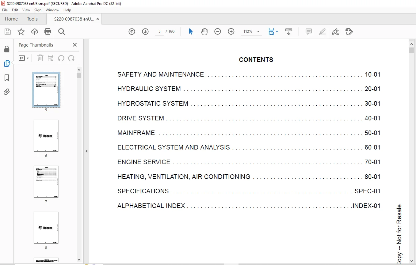
TABLE OF CONTENTS:
Bobcat S220 Skid-Steer Loader Service Manual 6987038 – PDF DOWNLOAD
MAINTENANCE SAFETY 3
CONTENTS 5
FOREWORD 7
FOREWORD 9
SAFETY INSTRUCTIONS 11
FIRE PREVENTION 13
Maintenance 13
Operation 13
Electrical 13
Hydraulic System 13
Fueling 13
Starting 13
Spark Arrester Exhaust System 13
Welding And Grinding 14
Fire Extinguishers 14
SERIAL NUMBER LOCATIONS 15
Loader Serial Number 15
Engine Serial Number 15
DELIVERY REPORT 15
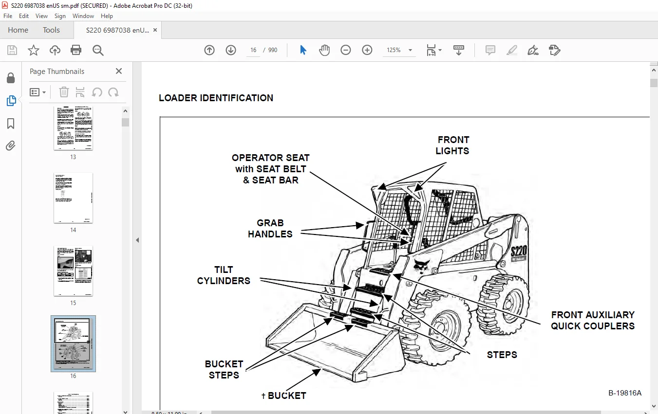
LOADER IDENTIFICATION 16
SAFETY AND MAINTENANCE 17
LIFTING AND BLOCKING THE LOADER 21
Procedure 21
LIFT ARM SUPPORT DEVICE 23
Installing 23
Removing 24
OPERATOR CAB 25
Description 25
Raising 26
Lowering 27
Cab Door Sensor 28
Special Applications Kit 28
Special Applications Kit Inspection And Maintenance 28
TRANSPORTING LOADER ON A TRAILER 29
Loading And Unloading 29
Fastening 29
TOWING THE LOADER 31
Procedure 31
REMOTE START TOOL KIT-MEL1563 33
Remote Start Tool – MEL1563 33
Service Tool Harness Control – MEL1565 34
Service Tool Harness Communicator – MEL1566 35
Remote Start Procedure 36
REMOTE START TOOL (SERVICE TOOL) KIT – 7217666 39
Description 39
Remote Start Tool (Service Tool) – 7022042 40
Loader Service Tool Harness – 6689747 41
Computer Service Tool Harness – 6689746 42
Remote Start Procedure 43
SERVICE SCHEDULE 47
Chart 47
AIR CLEANER SERVICE 49
Replacing Filter Elements 49
ENGINE COOLING SYSTEM 51
Maintenance Platform 51
Description 51
Cleaning (Earlier Models) 51
Cleaning (Later Models) 52
Removing And Replacing Coolant 54
Checking Level 54
FUEL SYSTEM 55
Fuel Specifications 55
Biodiesel Blend Fuel 55
Filling The Fuel Tank 56
Fuel Filter 57
Removing Air From The Fuel System 57
ENGINE LUBRICATION SYSTEM 59
Checking And Adding Engine Oil 59
Engine Oil Chart 59
Removing And Replacing Oil And Filter 60
HYDRAULIC / HYDROSTATIC SYSTEM 61
Checking And Adding Fluid 61
Hydraulic / Hydrostatic Fluid Chart 61
Removing And Replacing Hydraulic Fluid 62
Removing And Replacing Hydraulic / Hydrostatic Filter 63
Removing And Replacing Case Drain Filters 64
Removing And Replacing Hydraulic Charge Filter 65
Breather Cap 66
FINAL DRIVE TRANSMISSION (CHAINCASE) 67
Checking And Adding Oil 67
Removing And Replacing Oil 67
BOB-TACH (HAND LEVER) 69
Inspection And Maintenance 69
BOB-TACH (POWER) 71
Inspection And Maintenance 71
LUBRICATING THE LOADER 73
Lubrication Locations 73
TIRE MAINTENANCE 75
Wheel Nuts 75
Rotating 75
Mounting 76
PIVOT PINS 77
Inspection And Maintenance 77
SPARK ARRESTER MUFFLER 79
Cleaning Procedure 79
LOADER STORAGE AND RETURN TO SERVICE 81
Storage 81
Return To Service 81
STOPPING THE ENGINE AND LEAVING THE LOADER 83
Procedure 83
EMERGENCY EXIT 85
Rear Window 85
Front Door 85
SEAT BELT 87
Inspection And Maintenance 87
HYDRAULIC SYSTEM 89
HYDRAULIC/HYDROSTATIC SCHEMATICS 95
HYDRAULIC SYSTEM INFORMATION 111
Glossary Of Hydraulic / Hydrostatic Symbols 111
Troubleshooting 115
CYLINDER (LIFT) 117
Testing 117
Removal And Installation 118
Parts Identification 120
Disassembly 121
Assembly 123
CYLINDER (TILT) 125
Testing 125
Removal And Installation 126
Base End Pivot Pin Removal And Installation 128
Parts Identification 129
Disassembly 130
Assembly 132
CYLINDER (BOB-TACH) 135
Testing 135
Removal And Installation 136
Parts Identification 137
Disassembly 138
Assembly 139
MAIN RELIEF VALVE 143
Description 143
Testing 144
Adjusting 146
Removal And Installation 147
HYDRAULIC CONTROL VALVE (STANDARD) 149
Description 149
Removal And Installation 150
Identification Chart 154
Mount Bracket Removal And Installation 155
Lift Load Check Valve Removal And Installation 155
Load Check Valve Removal And Installation (Tilt And Auxiliary) 156
Anti-Cavitation Valve Removal And Installation (Lift, Rod End) 156
Port Relief / Anti-Cavitation Valve Removal And Installation (Lift, Base End) 157
Port Relief / Anti-Cavitation Valve Removal And Installation (Tilt, Base End) 158
Port Relief / Anti-Cavitation Valve Removal And Installation (Tilt, Rod End) 158
Port Relief Valve Removal And Installation 159
Plug Removal And Installation 160
Rubber Boot Removal And Installation 161
End Cap Block Removal And Installation 162
Lift Spool And Detent Removal And Installation 163
Tilt Spool Removal And Installation 173
Auxiliary Spool Removal And Installation 175
Auxiliary Solenoid Removal And Installation (S/N A5GK34999 & Below And A5GL34999 & Below) 177
Auxiliary Solenoid Removal And Installation (S/N A5GK35001 & Above And A5GL35001 & Above) 178
Solenoid Removal And Installation 179
Lock Valve Removal And Installation 180
Lift Arm Bypass Orifice Removal And Installation 182
Main Relief Valve Removal And Installation 182
Check Valve Removal And Installation 183
HYDRAULIC CONTROL VALVE (ACS) OR (SJC) 185
Description 185
Removal And Installation 186
Actuator Removal And Installation (In Loader) 190
Actuator Removal And Installation (Out Of Loader) 192
Identification Chart 195
Mount Bracket Removal And Installation 196
Lift Load Check Valve Removal And Installation 196
Load Check Valve Removal And Installation (Tilt And Auxiliary) 197
Anti-Cavitation Valve Removal And Installation (Lift, Rod End) 198
Port Relief / Anti-Cavitation Valve Removal And Installation (Lift, Base End) 199
Port Relief / Anti-Cavitation Valve Removal And Installation (Tilt, Base End) 199
Port Relief / Anti-Cavitation Valve Removal And Installation (Tilt, Rod End) 200
Port Relief Valve Removal And Installation 200
Plug Removal And Installation 201
End Cap Block Removal And Installation 202
Lift Spool And Detent Removal And Installation 203
Tilt Spool Removal And Installation 208
Auxiliary Spool Removal And Installation 210
Auxiliary Solenoid Removal And Installation (S/N A5GK34999 & Below And A5GL34999 & Below) 212
Auxiliary Solenoid Removal And Installation (S/N A5GK35001 & Above And A5GL35001 & Above) 213
Solenoid Removal And Installation 214
Lock Valve Removal And Installation 215
Lift Arm Bypass Orifice Removal And Installation 217
Main Relief Valve Removal And Installation 217
Check Valve Removal And Installation 218
LIFT ARM BYPASS CONTROL VALVE 219
Description 219
Testing 219
Removal And Installation 220
Disassembly And Assembly 221
HYDRAULIC PUMP (STANDARD) 223
Description 223
Pump Test At Quick Couplers 224
Direct Pump Test (Standard Section) 225
Direct Pump Test (Charge Section) 227
Removal And Installation 231
Hydraulic Pump Startup 233
Parts Identification 234
Disassembly And Assembly 235
HYDRAULIC PUMP (STANDARD) (HIGH FLOW) 237
Description 237
Pump Test At Quick Couplers 238
Direct Pump Test (Standard Section) 239
Direct Pump Test (Charge Section) 241
Direct Pump Test (High Flow Section) 245
High Flow Relief Valve Adjustment 247
High Flow Relief Valve Removal And Installation 249
Solenoid Removal And Installation 250
Removal And Installation 251
Hydraulic Pump Startup 253
Parts Identification 254
Disassembly And Assembly 255
HYDRAULIC PUMP (SJC) 257
Description 257
Pump Test At Quick Couplers 258
Direct Pump Test (Standard Section) 259
Direct Pump Test (Charge Section) 261
Removal And Installation 265
Hydraulic Pump Startup 267
Parts Identification 268
Disassembly And Assembly 269
HYDRAULIC PUMP (SJC) (HIGH FLOW) 271
Description 271
Pump Test At Quick Couplers 272
Direct Pump Test (Standard Section) 273
Direct Pump Test (Charge Section) 275
Direct Pump Test (High Flow Section) 279
High Flow Relief Valve Adjustment 281
High Flow Relief Valve Removal And Installation 283
Solenoid Removal And Installation 284
Removal And Installation 285
Hydraulic Pump Startup 287
Parts Identification 288
Disassembly And Assembly 289
HYDRAULIC / HYDROSTATIC FILTERS 291
Description 291
Housing Removal And Installation 291
HYDRAULIC FLUID RESERVOIR 293
Description 293
Removal And Installation 293
Hydraulic Fluid Screen 296
OIL COOLER 297
Description 297
Removal And Installation 297
BUCKET POSITION VALVE 301
Description 301
Solenoid Removal And Installation 302
Solenoid Testing 303
Removal And Installation 303
Disassembly And Assembly 304
REAR AUXILIARY DIVERTER VALVE 307
Description 307
Solenoid Testing 307
Removal And Installation 308
Disassembly And Assembly 310
BOB-TACH (POWER) BLOCK 317
Description 317
Removal And Installation 317
Disassembly And Assembly 319
FRONT AUXILIARY HYDRAULIC COUPLER BLOCK 323
Description 323
Removal And Installation 323
Disassembly And Assembly 324
HYDROSTATIC SYSTEM 327
HYDROSTATIC SYSTEM INFORMATION 329
Troubleshooting 329
Description 330
HYDROSTATIC DRIVE MOTOR 331
Description 331
Removal And Installation 332
Parts Identification 334
Disassembly And Assembly 335
HYDROSTATIC DRIVE MOTOR (TWO-SPEED) 339
Description 339
Removal And Installation 340
Parts Identification 343
Disassembly 345
Assembly 351
HYDROSTATIC MOTOR CARRIER 355
Description 355
Removal And Installation 356
Parts Identification 357
Disassembly 358
Assembly 359
HYDROSTATIC MOTOR CARRIER (SJC) 361
Description 361
Removal And Installation 362
Parts Identification 363
Disassembly 364
Assembly 366
CHARGE PRESSURE 369
Description 369
Testing 370
Sender Removal And Installation 372
Adjusting 373
HYDROSTATIC PUMP 375
Description 375
Removal And Installation 376
Hydrostatic Pump Startup 378
Replenishing / High Pressure Relief Valve Removal And Installation 379
Parts Identification (Left Half) 380
Parts Identification (Right Half) 381
Disassembly 382
Assembly 389
HYDROSTATIC PUMP (SJC) (S/N A5GK20001 – A5GK35063 AND A5GL20001 – A5GL35004) 395
Description 395
Hydraulic Controller Removal And Installation 396
Removal And Installation 398
Hydrostatic Pump Startup 400
Parts Identification 401
High Pressure Relief And Bypass Valve 402
Charge Relief Valve 403
Disassembly And Assembly 404
Mechanical Neutral Adjustment 421
Hydraulic Controller Neutral Adjustment 424
HYDROSTATIC PUMP (SJC) (S/N A5GK35064 & ABOVE AND A5GL35005 & ABOVE) 427
Description 427
Hydraulic Controller Removal And Installation 428
Removal And Installation 430
Hydrostatic Pump Startup 431
Parts Identification 432
High Pressure Relief And Bypass Valve 433
Charge Relief Valve 434
Disassembly And Assembly 435
Mechanical Neutral Adjustment 448
Hydraulic Controller Neutral Adjustment 451
DRIVE BELT 455
Description 455
Shield Removal And Installation 455
Adjusting 456
Belt Removal And Installation 456
Tensioner Pulley Removal And Installation 457
Tensioner Pulley Disassembly And Assembly 458
Tensioner Pulley Tension Spring Removal And Installation 459
Tensioner Pulley Tension Spring Disassembly And Assembly 459
CASE DRAIN FILTER 461
Description 461
Disassembly And Assembly 461
DRIVE SYSTEM 463
BRAKE 465
Description 465
Disc Removal And Installation 466
BRAKE (TWO-SPEED) 469
Description 469
Block Removal And Installation 470
Block Disassembly And Assembly 472
DRIVE COMPONENTS 477
Description 477
Axle Seal Removal And Installation 478
Axle, Sprocket And Bearings Removal And Installation 480
Chain Removal And Installation 485
CHAINCASE 487
Description 487
Front Cover Removal And Installation 487
Center Cover Removal And Installation 488
Rear Cover Removal And Installation 489
MAINFRAME 491
SEAT BAR 495
Description 495
Removal And Installation 495
Disassembly And Assembly 496
Compression Spring Disassembly And Assembly 497
OPERATOR CAB 499
Gas Cylinder Removal And Installation 499
Gas Cylinder Bracket Disassembly And Assembly 501
Removal And Installation 502
OPERATOR SEAT 505
Removal And Installation 505
Seat Belt Removal And Installation 505
OPERATOR SEAT (SUSPENSION) 507
Removal And Installation 507
Slide Rail Removal And Installation 508
Seat Belt Removal And Installation 508
Lower Cushion Removal And Installation 509
Back Cushion Removal And Installation 510
Shock Removal And Installation 510
3-Point Seat Belt Removal And Installation 511
BOB-TACH (HAND LEVER) 513
Description 513
Removal And Installation 513
Lever And Wedge Disassembly And Assembly 516
Pivot Pin Bushing And Seal Removal And Installation 517
BOB-TACH (POWER) 519
Description 519
Removal And Installation 519
Lever And Wedge Disassembly And Assembly 522
Pivot Pin Bushing And Seal Removal And Installation 524
LIFT ARMS 525
Removal And Installation 525
REAR GRILLE 529
Removal And Installation 529
REAR DOOR (TAILGATE) 531
Removal And Installation 531
Striker Removal And Installation 532
Striker Disassembly And Assembly 532
Striker (Adjusting) 533
Latch Removal And Installation 534
FUEL TANK 535
Removal And Installation 535
Fuel Level Sender Removal And Installation 538
Fuel Fill Screen Removal And Installation 538
CONTROL PEDALS AND LINKAGES 539
Description 539
Pedal Removal And Installation 540
Linkage Removal And Installation 541
Pedal (Adjusting) 542
CONTROL PEDALS (ACS) 543
Description 543
Foot Sensor Removal And Installation 544
Foot Pedal Removal And Installation 545
Foot Pedal Linkage Disassembly And Assembly 546
CONTROL PANEL 547
Description 547
Removal And Installation 548
Shock Removal And Installation 550
Shaft Removal And Installation 551
Linkage Removal And Installation 552
Pintle Arm Disassembly And Assembly 556
Linkage Neutral (Adjusting) 557
Linkage Travel (Adjusting) 561
CONTROL PANEL (SJC) 565
Description 565
Removal And Installation 566
CONTROL HANDLE / LEVER 569
Description 569
Lever Removal And Installation 569
Boot Removal And Installation 570
CONTROL HANDLE / LEVER (ACS) 571
Description 571
Handle Sensor Removal And Installation 571
Handle Removal And Installation 574
Handle Disassembly And Assembly 575
Lever Removal And Installation 576
Boot Removal And Installation 577
CONTROL HANDLE / LEVER (SJC) 579
Description 579
Joystick Testing 580
Joystick Removal And Installation 581
Joystick Mount Removal And Installation 582
ACCESS PANEL (INSIDE) 583
Removal And Installation (Left) 583
Removal And Installation (Right) 583
ACCESS PANEL (INSIDE) (SJC) 585
Removal And Installation (Left) 585
Removal And Installation (Right) 586
WINDOW (REAR) 589
Removal 589
Installation (Split Molding) 589
Installation (Continuous Molding) 591
WINDOW (TOP) 593
Removal And Installation 593
WINDOW (SIDE) 595
Removal And Installation 595
WINDOW (CAB DOOR) 597
Removal (Standard Window) 597
Installation (Standard Window) 598
Removal And Installation (Special Applications Window) 600
CAB DOOR 601
Description 601
Removal And Installation 601
Aligning 602
Adjusting 603
Checking Operation 603
ELECTRICAL SYSTEM AND ANALYSIS 605
ELECTRICAL SCHEMATICS 609
ELECTRICAL SYSTEM INFORMATION 615
Glossary Of Electrical Symbols 615
Cab Harness Connectors 618
Mainframe Harness Connectors 619
Description 621
Troubleshooting 622
Fuse And Relay Location / Identification 623
Solenoid Testing 624
BATTERY 625
Removal And Installation 625
Servicing 626
Using A Booster Battery (Jump Starting) 627
ALTERNATOR 629
Belt Adjustment 629
Belt Replacement 629
Charging System Inspection 630
Alternator Voltage Testing 631
Low Voltage Testing 631
High Voltage Testing 632
Removal And Installation 633
Parts Identification 634
STARTER 635
Testing 635
Removal And Installation 636
Parts Identification 637
INSTRUMENT PANELS 639
Left Panel 639
Standard Key Panel 641
Keyless Start Panel 641
Deluxe Instrumentation Panel 642
Side Panel 643
Front Panel 643
Front Panel Removal And Installation 644
Removal And Installation (Left And Right) 644
Key Switch Removal And Installation 646
Alarm Removal And Installation 647
LIGHTS 649
Front Removal And Installation 649
Rear Removal And Installation 650
Cab Light Removal And Installation 650
BOBCAT CONTROLLER (GATEWAY AND AUXILIARY) 651
Description 651
Connector Identification 652
Removal And Installation 658
BOBCAT CONTROLLER (ACS) 659
Description 659
Connector And Wire Identification 660
Removal And Installation 661
BOBCAT CONTROLLER (SJC) (DRIVE) 663
Description 663
Connector Identification 664
Removal And Installation 666
SPEED SENSORS (SJC) 667
Description 667
Testing 667
Removal And Installation 668
DIAGNOSTIC SERVICE CODES 671
Viewing Service Codes (Standard Key Panel And Keyless Start Panel) 671
Viewing Service Codes (Deluxe Instrumentation Panel) 671
Service Codes List 672
BOBCAT INTERLOCK CONTROL SYSTEM (BICS™) 677
Description 677
Inspecting The BICS™ (Engine STOPPED – Key ON) 678
Inspecting Deactivation Of The Auxiliary Hydraulics System (Engine STOPPED – Key ON) 678
Inspecting The Seat Bar Sensor (Engine RUNNING) 678
Inspecting The Traction Lock (Engine RUNNING) 678
Inspecting The Lift Arm Bypass Control 678
Inspecting Deactivation Of Lift And Tilt Functions (ACS and SJC) 678
Troubleshooting 679
SEAT BAR SENSOR 681
Description 681
Troubleshooting 682
Testing 683
Removal And Installation 684
Bobcat Interlock Control System (BICS™) Circuit Test 685
TRACTION LOCK 687
Description 687
Troubleshooting 688
Removal And Installation (Single Speed) 689
Inspecting (Single And Two Speed) 693
CONTROL SYSTEM (ACS) 695
Description 695
Troubleshooting 696
Handle Sensor Connector Disassembly And Assembly 697
Switch Handle Removal 698
Switch Handle Installation 700
Actuator Connector Disassembly And Assembly 703
Handle Lock Solenoid Removal And Installation 704
Handle Lock Solenoid Disassembly And Assembly 705
Foot Sensor Disassembly And Assembly 705
Foot Lock Solenoid Removal And Installation 706
ELECTRICAL / HYDRAULIC CONTROLS 707
Identification Chart 707
Description 708
Identification Chart ACD Group 0 709
Identification Chart ACD Group 1 710
Identification Chart ACD Group 2 711
Identification Chart ACD Group 3 712
ELECTRICAL / HYDRAULIC CONTROLS (ACS) 713
Identification Chart 713
Description 714
Identification Chart ACD Group 0 715
Identification Chart ACD Group 1 716
Identification Chart ACD Group 2 717
Identification Chart ACD Group 3 718
ELECTRICAL / HYDRAULIC CONTROLS (SJC) 719
Identification Chart 719
Description 720
Identification Chart ACD Group 0 721
Identification Chart ACD Group 1 722
Identification Chart ACD Group 2 723
Identification Chart ACD Group 3 724
SERVICE PC (LAPTOP COMPUTER) 725
Connecting Remote Start Tool 725
Connecting Remote Start Tool (Service Tool) 725
CALIBRATION 727
Description 727
Actuator Testing 727
Lift And Tilt Calibration (SJC) 730
Hydrostatic Pump Calibration (SJC) 732
Lift And Tilt Calibration (ACS) 737
STEERING DRIFT COMPENSATION 739
Description 739
Operation 739
FLYWHEEL RPM SENSOR 741
Description 741
Adjusting 742
CONTROL PANEL SETUP 743
Right Panel Setup (Deluxe Instrumentation Panel) 743
Attachment Control Information (Deluxe Instrumentation Panel) 744
PASSWORD SETUP (DELUXE INSTRUMENTATION PANEL) 745
Password Description 745
Changing The Owner Password 745
Changing The User Passwords 746
Password Lockout Feature 746
PASSWORD SETUP (KEYLESS START PANEL) 747
Password Description 747
Changing The Owner Password 747
Password Lockout Feature 747
MAINTENANCE CLOCK 749
Description 749
Setup 750
Reset 753
BACK-UP ALARM SYSTEM 755
Description 755
Inspecting 755
Adjusting Switch Position 756
Troubleshooting (Standard And ACS) 757
Troubleshooting (Joystick) 758
Alarm Removal And Installation 759
Switch Removal And Installation 759
ENGINE SERVICE 761
ENGINE INFORMATION 765
Description 765
Specifications 766
Torque Values 771
Troubleshooting 772
Engine Removal And Installation 774
Engine Mount Replacement 781
Compression – Checking 782
ENGINE SPEED CONTROL 783
Removal And Installation 783
Cable Removal And Installation 783
ENGINE SPEED CONTROL (SJC) 785
Removal And Installation 785
Disassembly And Assembly 787
Cable Removal And Installation 788
MUFFLER 789
Removal And Installation 789
AIR CLEANER 791
Housing Removal And Installation 791
ENGINE COOLING SYSTEM 793
Radiator Removal And Installation 793
Radiator Mount Removal And Installation 795
Hydraulic Fan Motor Description 796
Axial Fan Housing Removal And Installation 797
Axial Fan Removal And Installation 799
Hydraulic Fan Motor Removal And Installation 801
Hydraulic Fan Motor Disassembly And Assembly 801
Water Pump Removal And Installation 803
Water Pump Disassembly And Assembly 803
Thermostat Housing Removal And Installation 804
Thermostat – Checking 804
LUBRICATION SYSTEM 805
Oil Pan Removal And Installation 805
Oil Pump Removal And Installation 806
Oil Pump Inspection 806
Oil Filter Cooler Removal And Installation 808
Engine Oil Pressure – Testing 809
FUEL SYSTEM 811
Fuel Shutoff Solenoid – Checking 811
Fuel Shutoff Solenoid Removal And Installation 811
Fuel Injection Pump Assembly Removal 812
Fuel Injection Pump Assembly Installation 816
Governor Housing Disassembly And Assembly 818
Governor Disassembly And Assembly 820
Fuel Camshaft Removal And Installation 822
Fuel Injection Pump Removal 824
Injection Pump – Timing 831
Fuel Injector Removal And Installation 834
Fuel Injector Nozzle Pressure – Checking 835
Nozzle Spraying Condition 836
Valve Seat Tightness 836
CYLINDER HEAD 837
Intake Air Heater – Testing 837
Intake Air Heater Removal And Installation 837
Valve Clearance Adjustment 838
Valve Timing – Checking 840
Cylinder Head Removal And Installation 841
Cylinder Head Disassembly And Assembly 844
Cylinder Head – Servicing 844
Cylinder Head Top Clearance 845
Valve Guide – Checking 846
Reconditioning The Valve And Valve Seat 848
Valve Spring 850
Valve Tappets 851
Rocker Arm And Shaft – Checking 852
Push Rod Alignment – Checking 852
CRANKSHAFT AND PISTONS 853
Piston And Connecting Rod Removal And Installation 853
Piston And Connecting Rod – Servicing 855
Cylinder Bore – Checking 859
Connecting Rod Alignment 860
Crankshaft Gear Removal And Installation 860
Crankshaft And Bearings Removal 861
Crankshaft And Bearings Installation 863
Crankshaft And Bearings – Servicing 865
CAMSHAFT AND TIMING GEARS 871
Timing Gearcase Cover Removal And Installation 871
Timing Gears Backlash – Checking 872
Idler Gear And Camshaft Removal and Installation 872
Camshaft – Servicing 873
Idler Gear And Shaft – Servicing 875
TURBOCHARGER 877
Description 877
Testing 877
Removal And Installation 878
FLYWHEEL AND HOUSING 879
Flywheel Removal And Installation 879
Ring Gear Removal And Installation 879
Housing Removal And Installation 880
EXHAUST GAS RECIRCULATION (EGR) SYSTEM 881
Description 881
Testing 882
Removal And Installation 885
HEATING, VENTILATION, AIR CONDITIONING 887
AIR CONDITIONING SYSTEM FLOW 889
Description 889
Chart 890
Components 891
Safety Equipment 894
REGULAR MAINTENANCE 895
Filters 895
Compressor Drive Belt Adjustment 896
Compressor Drive Belt Replacement 896
Condenser 897
Air Conditioning Lubrication 897
Air Conditioning Service Chart 898
Evaporator / Heater Coil 899
TROUBLESHOOTING 901
Blower Motor Does Not Operate 901
Blower Motor Operates Normally, But Air Flow Is Insufficient 901
Insufficient Cooling Although Air Flow And Compressor Operation Are Normal 901
The Compressor Does Not Operate At All, Or Operates Improperly 901
Gauge Pressure Related Troubleshooting 902
Troubleshooting Tree 904
Temperature / Pressure Chart 908
Poor A/C Performance 910
HVAC Repair And Leaks 911
Electrical System 912
Engine Coolant Bypassing The Heater Valve 920
Heater Valve Not Opening Or Closing 921
SYSTEM CHARGING AND RECLAMATION 923
Refrigerant Identification 923
Reclamation And Charging With Recovery / Charging Unit 924
Charging With A Manifold Gauge Set 926
COMPRESSOR 929
Removal And Installation 929
Oil 930
Oil Check 931
Clutch Disassembly And Assembly 932
CONDENSER 937
Removal And Installation 937
RECEIVER / DRIER 939
Receiver / Drier Removal And Installation 939
Pressure Relief Valve Removal And Installation 940
Pressure Switch Removal And Installation 940
Schraeder Valve Removal And Installation 941
EVAPORATOR / HEATER UNIT 943
Removal And Installation 943
THERMOSTAT 945
Description 945
Removal And Installation 946
EXPANSION VALVE 947
Removal And Installation 947
EVAPORATOR COIL 949
Removal And Installation 949
HEATER COIL 951
Removal And Installation With A/C 951
Removal And Installation Without A/C 953
BLOWER FAN 955
Removal And Installation 955
Disassembly And Assembly 956
Connector Identification 958
HEATER VALVE 959
Removal And Installation 959
Disassembly And Assembly 960
SPECIFICATIONS 961
(S220) LOADER SPECIFICATIONS 963
Machine Dimensions 963
Performance 964
Hydraulic System 964
Engine 965
Controls 965
Drive System 965
Electrical 966
Capacities 966
Tires 966
TORQUE SPECIFICATIONS FOR BOLTS 967
Torque For General SAE Bolts 967
Torque For General Metric Bolts 968
HYDRAULIC CONNECTION SPECIFICATIONS 969
O-ring Face Seal Connection 969
Straight Thread O-ring Fitting 970
Tubelines And Hoses 970
Flare Fitting 971
Port Seal Fitting 972
HYDRAULIC / HYDROSTATIC FLUID SPECIFICATIONS 973
Specifications 973
CONVERSIONS 975
Decimal And Millimeter Equivalent Chart 975
U S To Metric Conversion Chart 975
SERVICE TOOLS REQUIRED 977
Remote Start Tools 977
Hydraulic Tools 978
Mainframe And Drive Tools 980
Electrical Tools 981
Engine Tools 981
HVAC Tools 986
ALPHABETICAL INDEX 987
IMAGES PREVIEW OF THE MANUAL:
Contact us: [email protected]
PLEASE NOTE:
- This is the same manual used by the DEALERSHIPS to SERVICE your vehicle.
- The manual can be all yours – Once payment is complete, you will be taken to the download page from where you can download the manual. All in 2-5 minutes time!!
- Need any other service / repair / parts manual, please feel free to contact us at heydownloadss @gmail.com . We may surprise you with a nice offer
S.V


