Bobcat S220 Turbo S220 Turbo High Flow Loader Service Manual 6902447 (6-12) – PDF DOWNLOAD
$34.95
Bobcat S220 Turbo S220 Turbo High Flow Loader Service Manual 6902447 (6-12) – PDF DOWNLOAD
S/N 523211001 & Above
S/N 523311001 & Above
Description
Bobcat S220 Turbo S220 Turbo High Flow Loader Service Manual 6902447 (6-12) – PDF DOWNLOAD
FILE DETAILS:
Bobcat S220 Turbo S220 Turbo High Flow Loader Service Manual 6902447 (6-12) – PDF DOWNLOAD
Language : English
Pages : 910
Downloadable : Yes
File Type : PDF
DESCRIPTION:
Bobcat S220 Turbo S220 Turbo High Flow Loader Service Manual 6902447 (6-12) – PDF DOWNLOAD
S/N 523211001 & Above
S/N 523311001 & Above
FOREWORD:
This manual is for the Bobcat loader mechanic. It provides necessary servicing and adjustment procedures for the Bobcat loader and its component parts and systems. Refer to the Operation & Maintenance Manual for operating instructions, Starting procedure, daily checks, etc.
A general inspection of the following items must be made after the loader has had service or repair:
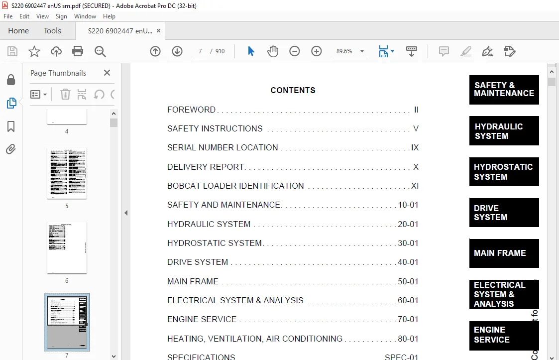
TABLE OF CONTENTS:
Bobcat S220 Turbo S220 Turbo High Flow Loader Service Manual 6902447 (6-12) – PDF DOWNLOAD
MAINTENANCE SAFETY 3
ALPHABETICAL INDEX 5
CONTENTS 7
FOREWORD 8
SAFETY INSTRUCTIONS 11
Fire Prevention 13
SERIAL NUMBER LOCATION 15
Loader Serial Number 15
Engine Serial Number 15
DELIVERY REPORT 16
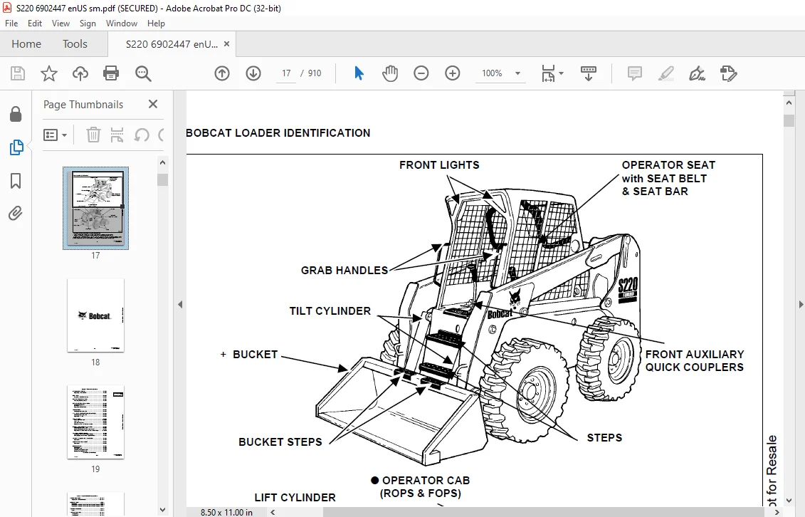
BOBCAT LOADER IDENTIFICATION 17
SAFETY AND MAINTENANCE 19
LIFTING AND BLOCKING THE LOADER 21
Procedure 21
LIFT ARM SUPPORT DEVICE 23
Engaging The Lift Arm Support Device 23
Disengaging The Lift Arm Support Device 24
OPERATOR CAB 25
Description 25
Raising The Operator Cab 25
Lowering The Operator Cab 26
Emergency Exit 26
TRANSPORTING THE BOBCAT LOADER 29
Procedure 29
TOWING THE LOADER 31
Procedure For Non-Two-Speeds 31
REMOTE START 33
Procedure For Loader W/O Attachments Control Harness 33
Procedure For Loader With Attachments Control Harness 34
Procedure 35
SERVICE SCHEDULE 37
Chart 37
AIR CLEANER SERVICE 39
Replacing Filter Element 39
ENGINE COOLING SYSTEM 41
Cleaning Cooling System 41
FUEL SYSTEM 43
Fuel Specifications 43
Filling The Fuel Tank 43
Fuel Filter 43
Removing Air From The Fuel System 44
ENGINE LUBRICATION SYSTEM 45
Checking Engine Oil 45
Oil Chart 45
Replacing Oil And Filter 45
HYDRAULIC/HYDROSTATIC SYSTEM 47
Checking And Adding Fluid 47
Hydraulic/Hydrostatic Filter Replacement 47
Replacing Hydraulic Fluid And Case Drain Filters 48
FINAL DRIVE TRANSMISSION (CHAINCASE) 51
Checking And Adding Oil 51
Replacing The Oil 51
FAN GEARBOX 53
Checking And Adding Oil 53
BOB-TACH 55
Inspection And Maintenance 55
POWER BOB-TACH 57
Inspection And Maintenance 57
LUBRICATING THE LOADER 59
Procedure 59
TIRE MAINTENANCE 61
Wheel Nuts 61
Tire Rotation 61
Tire Mounting 61
HYDRAULIC SYSTEM 63
HYDRAULIC/HYDROSTATIC SCHEMATICS 69
HYDRAULIC SYSTEM INFORMATION 85
Troubleshooting 89
Tightening Procedure 90
CYLINDER (LIFT) 91
Checking 91
Removal And Installation 91
Parts Identification 93
Disassembly 94
Assembly 95
CYLINDER (TILT) 99
Checking 99
Removal And Installation 99
Base Pin Removal And Installation 101
Parts Identification 102
Disassembly 103
Assembly 104
CYLINDER (POWER BOB-TACH) 107
Checking 107
Removal And Installation 108
Parts Identification 109
Disassembly 110
Assembly 111
MAIN RELIEF VALVE (FOOT CONTROL) 115
Checking The Main Relief Valve At Front Aux Hyd 115
Removal And Installation 116
Adjustment 116
MAIN RELIEF VALVE (ACS) 117
Checking The Main Relief Valve At Front Aux Hyd 117
Removal And Installation 118
Adjustment 119
MAIN RELIEF VALVE (SELECTABLE JOYSTICK CONTROL) (SJC) 121
Checking The Main Relief Valve At Front Auxiliary Hydraulics 121
Removal and Installation 122
Adjustment 123
HYDRAULIC CONTROL VALVE (FOOT CONTROL) 125
Removal And Installation 125
BICS™ Valve, Removal And Installation 129
BICS™ Valve, Lift Arm By-Pass Orifice Removal And Installation 130
BICS™ Valve, Check Valve Removal And Installation 131
Backslide, Lock Valve Removal And Installation 132
BICS™ Valve, Solenoid Removal And Installation 133
BICS™ Valve, Solenoid Testing 134
Identification Chart 134
Load Check Valve 135
Main Relief Valve 136
Port Relief Valve, Tilt Spool 136
Port Relief Valve, Lift Spool 137
Anti-Cavitation Valve/Port Relief Valve, Tilt Spool 137
Anti-Cavitation Valve, Lift Spool 138
Rubber Boot 138
Lift And Tilt Lock Block 139
Lift Spool And Detent Removal 140
Lift Spool And Detent Disassembly 142
Lift Spool And Detent Assembly 144
Lift Spool And Detent Installation 148
Tilt Spool Removal And Installation 148
Tilt Spool Disassembly And Assembly 149
Auxiliary Spool Removal And Installation 150
Auxiliary Plug Removal And Installation 152
Auxiliary Electric Solenoid Disassembly 153
Port-Auxiliary Section Removal And Installation 154
Cleaning And Inspection 154
HYDRAULIC CONTROL VALVE (ADVANCED CONTROL SYSTEM) (ACS) 155
Actuator Removal And Installation (In Loader) 155
Actuator Removal And Installation (Out Of Loader) 158
Removal And Installation 159
BICS™ Valve, Removal And Installation 163
BICS™ Valve, Lift Arm By-Pass Orifice Disassembly And Assembly 165
BICS™ Valve, Check Valve Disassembly And Assembly 166
BICS™ Valve, Lock Valve Disassembly And Assembly 167
BICS™ Valve, Solenoid Disassembly And Assembly 168
BICS™ Valve, Solenoid Testing 169
Identification Chart 170
Lift Base End Restrictor 171
Load Check Valve 171
Main Relief Valve 172
Port Relief Valve 173
Anti-Cavitation Valve/Port Relief Valve 174
Anti-Cavitation Valve 175
Lift Spool Removal 176
Lift Spool Removal And Installation 177
Lift and Tilt Spool Disassembly And Assembly 178
Auxiliary Spool Removal And Installation 179
Auxiliary Electric Solenoid Disassembly 180
Port-Auxiliary Section Disassembly 181
Cleaning And Inspection 181
HYDRAULIC CONTROL VALVE (SELECTABLE JOYSTICK CONTROL) (SJC) 183
Actuator Removal And Installation (In Loader) 183
Actuator Removal And Installation (Out Of Loader) 186
Removal And Installation 187
BICS™ Valve, Removal And Installation 191
BICS™ Valve, Lift Arm By-Pass Orifice Disassembly And Assembly 193
BICS™ Valve, Check Valve Disassembly And Assembly 194
BICS™ Valve, Lock Valve Disassembly And Assembly 195
BICS™ Valve, Solenoid Disassembly And Assembly 196
BICS™ Valve, Solenoid Testing 197
Identification Chart 198
Lift Base End Restrictor 199
Load Check Valve 199
Main Relief Valve 200
Port Relief Valve 201
Anti-Cavitation Valve/Port Relief Valve 202
Anti-Cavitation Valve 203
Lift Spool Removal 204
Lift Spool Removal And Installation 205
Lift and Tilt Spool Disassembly And Assembly 206
Auxiliary Spool Removal And Installation 207
Auxiliary Electric Solenoid Disassembly 208
Port-Auxiliary Section Disassembly 209
Cleaning And Inspection 209
LIFT ARM BY-PASS CONTROL VALVE 211
Inspecting 211
Additional Inspection For Loaders W/Advanced Hand Controls 211
Removal And Installation 211
Disassembly And Assembly 212
HYDRAULIC PUMP 213
Check The Output Of The Hydraulic Pump 213
Removal And Installation 214
Identification 216
Disassembly And Assembly 217
HYDRAULIC PUMP (CHARGE) 225
Check The Output Of The Hydraulic Pump 225
Removal And Installation 228
Disassembly And Assembly 228
HYDRAULIC PUMP (HI FLOW) 229
Hydraulic Pump Test 229
Inline Hydraulic Pump Test (Standard) 230
Inline Hydraulic Pump Test (High Flow) 232
High Flow Relief Adjustment Procedure 234
High Flow Relief Valve Removal and Installation 236
Removal And Installation 238
Identification 240
Disassembly And Assembly 241
HYDRAULIC PUMP (SELECTABLE JOYSTICK CONTROL) (SJC) 255
Check The Output Of The Hydraulic Pump 255
Removal And Installation 256
Identification 258
Disassembly And Assembly 259
HYDRAULIC PUMP (HI-FLOW) (SELECTABLE JOYSTICK CONTROL) (SJC) 265
Hydraulic Pump Test 265
Inline Hydraulic Pump Test (Standard) 266
Inline Hydraulic Pump Test (High Flow) 268
High Flow Relief Adjustment Procedure 270
High Flow Relief Valve Removal and Installation 272
Removal And Installation 274
Identification 276
Disassembly And Assembly 277
HYDRAULIC/HYDROSTATIC FILTER 287
Housing Removal And Installation 287
Mount Removal And Installation 288
HYDRAULIC FLUID RESERVOIR 289
Fluid Removal 289
Removal And Installation 289
Hydraulic Fluid Screen 292
BUCKET POSITION VALVE 295
Solenoid Removal And Installation 295
Solenoid Testing 295
Removal And Installation 296
Disassembly And Assembly 296
REAR AUXILIARY DIVERTER 299
Removal and Installation 299
REAR AUXILIARY DIVERTER (CONT’D) 300
Disassembly And Assembly 301
Solenoid Testing 306
Inspection 306
POWER BOB-TACH BLOCK (EARLY MODELS) 307
Removal And Installation 307
Disassembly And Assembly 308
POWER BOB-TACH BLOCK (LATER MODELS) 317
Removal And Installation 317
Disassembly And Assembly 318
FRONT AUXILIARY HYDRAULIC COUPLER BLOCK 323
Removal and Installation 323
Disassembly And Assembly 323
HYDROSTATIC SYSTEM 325
HYDROSTATIC SYSTEM INFORMATION 327
Troubleshooting 327
Replenishing Valve Function 328
HYDROSTATIC MOTOR 329
Removal And Installation 329
Parts Identification 330
Disassembly 331
Inspection 333
Assembly 334
HYDROSTATIC MOTOR (TWO-SPEED) 339
Removal And Installation 339
Parts Identification 341
Disassembly 343
Inspection 350
Assembly 351
HYDROSTATIC MOTOR CARRIER 359
Removal and Installation 359
Parts Identification 361
Disassembly 362
Assembly 363
HYDROSTATIC MOTOR CARRIER (SELECTABLE JOYSTICK CONTROL) (SJC) 365
Removal And Installation 365
Parts Identification 366
Assembly 369
CHARGE PRESSURE SENDER 373
Testing 373
CHARGE PRESSURE SENDER (CONT’D) 374
Removal and Installation 374
Setting Charge Pressure 375
HYDROSTATIC PUMP 377
Removal And Installation 377
Replenishing/High Pressure Relief Valve 379
Parts Identification (Right Half) 380
Parts Identification (Left Half) 382
Hydraulic Pump Removal And Installation 384
Pump Separation 384
Disassembly 385
Assembly 391
HYDROSTATIC PUMP (SELECTABLE JOYSTICK CONTROL) (SJC) 399
Pump Controller Removal And Installation 399
Hydrostatic Pump Calibration 402
Removal And Installation 406
Parts Identification (Right Half) 409
Parts Identification (Left Half) 411
System Check Relief Valves (High Pressure Relief, Charge Check & By-Pass Valve) 413
Charge Relief Valve 414
Pump Separation 416
Shaft Seal And Shaft Replacement 417
Shaft Seal And Shaft Installation 419
Charge Pump Removal 421
Charge Pump Inspection 423
Charge Pump Installation 424
Disassembly 426
Inspection 433
Assembly 437
Pump Neutral Adjustment 446
Pump Controller Neutral Adjustment 449
DRIVE BELT 453
Shield Removal And Installation 453
Adjustment 453
Replacement 453
Tensioner Pulley Removal And Installation 454
Tensioner Pulley Tension Spring 456
OIL COOLER (SEAL TO CONNECT) (STC) 457
Hydraulic Oil Cooler Removal and Installation 457
OIL COOLER (SEAL TO CONNECT) (STC) (CONT’D) 458
Hydraulic Oil Cooler Removal and Installation (Cont,d) 458
DRIVE SYSTEM 459
BRAKE 461
Disc Removal And Installation 461
BRAKE (TWO-SPEED) 465
Block Removal And Installation 465
Block Disassembly And Assembly 466
DRIVE COMPONENTS 471
Axle Seal Removal And Installation 471
Axle, Sprocket And Bearings Removal And Installation 473
Drive Chain Removal And Installation 477
CHAINCASE 479
Front Chaincase Cover Removal And Installation 479
Rear Chaincase Cover Removal And Installation 479
MAIN FRAME 481
SEAT BAR 483
Removal And Installation 483
Assembling Components 484
Compression Spring Disassembly And Assembly 485
OPERATOR CAB 487
Gas Cylinder Removal And Installation (Dual Gas Spring) 487
Gas Cylinder Removal And Installation (3rd Gas Spring) 489
Gas Cylinder Bracket Disassembly And Assembly 491
Removal And Installation 491
OPERATOR SEAT 495
Removal And Installation 495
Seat Belt Removal And Installation 495
OPERATOR SEAT (SUSPENSION) 497
Removal And Installation 497
Slide Rail Removal And Installation 498
Cushion Removal And Installation 498
Back Removal And Installation 499
Shock Removal And Installation 500
3-Point Seat Belt Removal And Installation 501
BOB-TACH 503
Removal And Installation 503
Bob-Tach Lever And Wedge 505
POWER BOB-TACH 507
Removal And Installation 507
Power Bob-Tach Lever And Wedge 509
Pivot Pin Bushing And Seal Replacement 511
LIFT ARMS 513
Removal And Installation 513
REAR GRILL 517
Removal And Installation 517
REAR DOOR 519
Removal And Installation 519
Adjusting The Rear Door Latch 520
FUEL TANK 521
Removal And Installation 521
Fuel Level Sender 522
CONTROL PEDALS 523
Removal And Installation 523
Pedal Adjustment 523
CONTROL PEDALS (ACS) 525
Foot Sensor Removal And Installation 525
Foot Pedal Removal And Installation 526
Foot Pedal Linkage Disassembly And Assembly 526
CONTROL PANEL 527
Removal And Installation 527
Shock Removal And Installation 529
Shaft Removal And Installation 529
Shaft Disassembly And Assembly 529
Linkage Removal And Installation 531
Linkage Neutral Adjustment 534
CONTROL PANEL (SELECTABLE JOYSTICK CONTROL) (SJC) 541
Removal And Installation 541
CONTROL HANDLE 545
Lever Removal And Installation 545
Steering Lever Boot 545
CONTROL HANDLE (ADVANCED CONTROL SYSTEM) (ACS) SELECTABLE HAND/FOOT CONTROL 547
Components Identification 547
Handle Sensor Removal And Installation 547
Control Handle Removal And Installation 550
Control Handle Disassembly And Assembly 551
Control Lever Removal And Installation 552
Control Lever Boot 553
CONTROL HANDLE (SELECTABLE JOYSTICK CONTROL) (SJC) 555
Joystick Testing (Right & Left) 555
Joystick Removal (Right & Left) 556
Joystick Boot Removal (Right & Left) 557
Lever Assembly Removal (Right & Left) 557
INSIDE ACCESS PANEL 559
Removal And Installation (Left) 559
Removal And Installation (Right) 559
INSIDE ACCESS PANEL (SELECTABLE JOYSTICK CONTROL) (SJC) 561
Panel Removal (Right) 561
Panel Removal (Left) 564
ELECTRICAL SYSTEM & ANALYSIS 565
ELECTRICAL SCHEMATICS 569
ELECTRICAL SYSTEM INFORMATION 575
Troubleshooting 577
Description 578
Fuse Location 580
Relay Switch Location 580
Solenoid Test 581
BATTERY 583
Removal And Installation 583
Servicing The Electrical System 585
Using A Booster Battery (Jump Starting) 586
ALTERNATOR 587
Adjusting The Alternator Belt 587
Alternator Identification 587
Charging System Check 588
Alternator Voltage Test 589
Low Voltage Test 589
High Voltage Test 590
Removal And Installation 590
Rectifier Continuity (Diode) Test 591
Alternator Regulator Test 592
Disassembly 593
Stator Continuity Test 593
Stator Ground Test 593
Rotor Continuity Test 594
Rotor Ground Test 594
Assembly 594
STARTER 595
Removal And Installation 595
Parts Identification 596
Checking 597
Disassembly And Assembly 598
Inspection And Repair 601
No Load Test 604
INSTRUMENT PANEL 605
Left Panel 605
Right Panel (Standard) (With Key Switch) 606
Right Panel (Deluxe) (With Keyless Start) 607
Right Panel Setup Display Options (Deluxe) 609
Deluxe Panel Setup 610
Passwords (Deluxe) 610
Option And Field Accessory Panels (If Equipped) 612
Standard Panel Removal And Installation (Right Side) 613
Deluxe Panel Removal And Installation (Right Side) 614
Standard & Deluxe Panel Removal And Installation (Left Side) 615
Front Accessory Panel Removal And Installation 616
LIGHTS 617
Front Removal And Installation 617
Rear Removal And Installation 617
CONTROLLER (BOBCAT) 620
Identification Chart 620
Removal And Installation 622
CONTROLLER (SELECTABLE JOYSTICK CONTROL) (SJC) 623
Removal 623
Identification Chart 626
SPEED SENSOR (SELECTABLE JOYSTICK CONTROL) (SJC) 629
Testing 629
Removal 630
DIAGNOSTICS SERVICE CODES 633
Display 633
Number Codes List 634
BICS™ SYSTEM 639
Inspecting The fBICS™ Controller (Engine STOPPED – Key ON) 639
Inspecting Deactivation Of The Auxiliary Hydraulics System (Engine STOPPED – Key ON) 639
Inspecting The Seat Bar Sensor (Engine RUNNING) 639
Inspecting The Traction Lock (Engine RUNNING) 639
Inspecting The Lift Arm By-Pass Control 640
Additional Inspection For Loaders With Advanced Controls System (ACS) or Selectable Joystick Control (SJC) 640
Troubleshooting 641
Troubleshooting Guide 642
SEAT BAR SENSOR 643
Troubleshooting Chart 643
Test 644
Removal And Installation 645
BICS™ Circuit Test 646
TRACTION LOCK 647
Troubleshooting 647
Removal And Installation (Single Speed) 648
Description Of The Control System (Two Speed) 649
Inspecting The Control System (Two Speed) 649
ADVANCED CONTROL SYSTEM (ACS) 651
Components Identification 651
Troubleshooting Guide 653
Controller, Connector And Wire Identification 654
ACS Controller Removal And Installation 655
Handle Sensor Connector 656
Switch Handle Removal 657
Switch Handle Installation 659
Actuators Disassembly And Assembly 662
Handle Lock Solenoid Removal And Installation 663
Handle Lock Solenoid Disassembly And Assembly 663
Handle Lock Solenoid Connector 664
Calibration Of The ACS System 664
Switchable Hand/Foot Controls Calibration Procedure 665
Hand Controls Only Calibration Procedure 666
Foot Sensor Disassembly And Assembly 667
Foot Sensor Connector 668
Foot Lock Solenoid Removal And Installation 668
Foot Lock Solenoid Connector 669
ELECTRICAL/HYDRAULIC CONTROLS REFERENCE 671
Controls Identification Chart 671
ELECTRICAL/HYDRAULIC CONTROLS REFERENCE (SELECTABLE JOYSTICK CONTROL) (SJC) 673
Controls Identification Chart 673
SERVICE PC (LAPTOP COMPUTER) 677
Connecting The Service PC To Remote Start Tool 677
LIFT AND TILT ACTUATOR CALIBRATION (SELECTABLE JOYSTICK CONTROL) (SJC) 679
Procedure 679
FLYWHEEL RPM SENSOR 681
Adjustment 681
ENGINE SERVICE 683
TROUBLESHOOTING 687
Chart 687
ENGINE SPEED CONTROL 689
Removal And Installation 689
Speed Control Cable 690
ENGINE SPEED CONTROL (SELECTABLE JOYSTICK CONTROL) (SJC) 693
Removal 693
Disassembly 695
Speed Control Cable 696
MUFFLER 697
Removal And Installation 697
AIR CLEANER 699
Housing Removal And Installation 699
RADIATOR 701
Removal And Installation 701
Mount Removal 703
COOLING FAN 705
Drive Tension Pulley Removal And Installation 705
Gearbox/Blower Housing Removal And Installation 706
Blower Removal And Installation 707
Gearbox Parts Identification 709
Gearbox Disassembly 710
Gearbox Assembly 715
Gearbox, Checking Backlash 720
ENGINE 723
Removal And Installation 723
Mount Replacement 730
Removal And Installation Tools 731
FLYWHEEL AND HOUSING 733
Flywheel Removal And Installation 733
Ring Gear Removal And Installation 733
Flywheel Housing Removal And Installation 733
RECONDITIONING THE ENGINE 735
Engine Tools Identification Chart 735
Compression Pressure 739
Cylinder Head Clearance 739
Valve Cover And Injector Nozzle Removal And Installation 740
Rocker Arm And Push Rod Disassembly And Assembly 742
Valve Clearance 742
Cylinder Head And Tappet Disassembly And Assembly 743
Selecting Cylinder Head Gasket Disassembly And Assembly 744
Valve Disassembly And Assembly 745
Engine Timing (TDC) 746
Injection Pump Assembly Removal 747
Injection Pump Assembly Installation 750
Injection Pump Removal and Installation 753
Injection Pump Timing 755
Fan Drive Pulley Disassembly And Assembly 758
Water Pump Disassembly And Assembly 758
Gearcase Cover Disassembly And Assembly 759
Idle Gear And Camshaft Disassembly And Assembly 759
Gearcase Plate Disassembly And Assembly 760
Oil Pan And Oil Strainer Disassembly And Assembly 760
Connecting Rod Cap Disassembly And Assembly 761
Piston Disassembly And Assembly 762
Piston Ring And Connecting Rod Disassembly And Assembly 763
Bearing Case Cover Disassembly And Assembly 765
Flywheel Housing Disassembly And Assembly 766
Crankcase No 2 Disassembly And Assembly 766
Crankcase No 1 And No 2 Disassembly And Assembly 767
Crankshaft Disassembly And Assembly 767
Cylinder Head Surface Flatness 767
Cylinder Head Flaw 768
Valve Recessing 768
Valve Lapping 769
Clearance Between Valve Stem And Valve Guide 769
Replacing Valve Guide 770
Correcting Valve And Valve Seat 770
Free Length And Tilt Of Valve Spring 771
Valve Spring Setting Load 771
Oil Clearance Between Rocker Arm Shaft And Bearing 772
Oil Clearance Between Tappet And Tappet Guide Bore 772
Timing Gear Backlash 773
Idler Gear Side Clearance 773
Camshaft Side Clearance 774
Camshaft Alignment 774
Cam Height 774
Oil Clearance Of Camshaft Journal 775
Oil Clearance Between Idler Gear Shaft And Idler Gearing Bushing 775
Replacing Idler Gear Bushing 776
Piston Pin Bore I D 777
Oil Clearance Between Piston Pin And Small End Bushing 777
Replacing Small End Bushing 778
Clearance Between Piston Ring And Groove 778
Piston Ring Gap 779
Connecting Rod Alignment 779
Crankshaft Side Clearance 780
Crankshaft Alignment 781
Oil Clearance Between Crankpin And Crankpin Bearing 781
Oil Clearance Between Crankshaft Journal And Crankshaft Bearing 783
Replacing Crankshaft Sleeve 784
Cylinder Bore I D 784
Correcting Cylinder (Oversize +0 5 mm) 785
Engine Oil Pressure 785
Rotor Lobe Clearance 786
Clearance Between Outer Rotor And Pump Body 786
Thermostat Valve Opening Temperature 786
Radiator Water Leakage 787
Radiator Cap Air Leakage 787
Thermostat Assembly 787
Intake Air Heater 788
Checking the Turbo Charger 789
Compressor Side 789
Wheel Shaft 789
Axial Clearance 790
Radial Clearance 790
Air Cleaner, Intake Pipe, Inlet Pipe And Muffler 790
Oil Pipe 791
Turbocharger 791
HEATING, VENTILATION, AIR CONDITIONING 793
AIR CONDITIONING SYSTEM FLOW 796
Principles 796
Chart 797
COMPONENTS 799
Identification 799
SAFETY 803
Safety Equipment 803
REGULAR MAINTENANCE 805
Filter Elements Removal And Installation 805
Compressor Drive Belt Inspection 806
Cleaning The Condenser 807
BASIC TROUBLESHOOTING 809
Poor A/C Performance 809
Cleaning The A/C Evaporator Coil & Heater Coil 810
Compressor Drive Belt Inspection 810
Checking The Electrical System 811
Engine Coolant By-Passing The Heater Valve 819
Heater Valve Not Opening Or Closing 820
GENERAL AIR CONDITIONING SERVICE GUIDELINES 821
Compressor Oil 821
Compressor Oil Check 822
Component Replacement And Refrigeration Leaks 823
SYSTEM TROUBLESHOOTING CHART 825
Gauge Pressure Related Troubleshooting 826
Troubleshooting Tree 828
TEMPERATURE/PRESSURE 833
Chart 833
AIR CONDITIONING SERVICE 835
Chart 835
SYSTEM CHARGING AND RECLAMATION 837
Reclamation Procedure 837
Charging Procedure With A Manifold Gauge Set 839
Charging Procedure 840
COMPRESSOR 843
Removal And Installation 843
Compressor Clutch Disassembly 844
CONDENSER 849
Removal And Installation 849
RECEIVER/DRIER 851
Removal And Installation 851
PRESSURE RELIEF VALVE 853
Removal And Installation 853
PRESSURE SWITCH 855
Removal And Installation 855
EVAPORATOR/HEATER UNIT 857
Removal And Installation 857
Disassembly And Assembly 858
THERMOSTAT 859
Removal And Installation 859
EXPANSION VALVE 861
Removal And Installation 861
EVAPORATOR 863
Removal And Installation 863
HEATER COIL 865
Removal And Installation With A/C 865
Removal And Installation Without A/C 866
BLOWER FAN 867
Removal And Installation 867
Disassembly And Assembly 868
Wire Connector Removal and Installation 870
HEATER VALVE 873
Removal and Installation 873
Disassembly And Assembly 874
SPECIFICATIONS 877
LOADER SPECIFICATIONS (S220) 879
Machine Dimensions 879
Performance 880
Controls 880
Engine 880
Hydraulic System 881
Electrical 881
Drive System 882
Capacities 882
Tires 882
ENGINE SPECIFICATIONS 883
General 883
Fuel System 883
Valve And Valve Timing 883
Valve Spring 884
Piston And Piston Ring 884
Connecting Rod 884
Cylinder Head 885
Crankshaft 885
Cylinder Bore 885
Oil Pump 885
Rocker Arm 886
Tappet 886
Camshaft 886
Thermostat 886
Timing Gear 887
Intake Air Heater 887
TORQUE SPECIFICATIONS FOR BOLTS 889
Torque For General SAE Bolts 889
Torque For General Metric Bolts 890
Torque For Kubota Metric Engine Bolts 891
Tightening Torques For General Use Screws, Bolts And Nuts 891
HYDRAULIC CONNECTION SPECIFICATIONS 893
O-ring Face Seal Connection 893
Straight Thread O-ring Fitting 894
Tubelines And Hoses 894
Flare Fitting 894
O-ring Flare Fitting 895
Port Seal Fitting 897
HYDRAULIC FLUID SPECIFICATIONS 899
Specifications 899
CONVERSIONS 901
Decimal And Millimeter Equivalents 901
SMR 903
S220-1 903
S220-2 905
S220-3 907
S220-4 909
IMAGES PREVIEW OF THE MANUAL:
Need help? Contact: [email protected]
https://vimeo.com/843770528?share=copy
PLEASE NOTE:
- This is the same manual used by the DEALERSHIPS to SERVICE your vehicle.
- The manual can be all yours – Once payment is complete, you will be taken to the download page from where you can download the manual. All in 2-5 minutes time!!
- Need any other service / repair / parts manual, please feel free to contact us at heydownloadss @gmail.com . We may surprise you with a nice offer
S.V