Bobcat S220 Turbo S220 Turbo High Flow Service Manual 6902722 (6-12) – PDF DOWNLOAD
$36.95
Bobcat S220 Turbo S220 Turbo High Flow Service Manual 6902722 (6-12) – PDF DOWNLOAD
S/N 526211001 & Above
S/N 526311001 & Above
Description
Bobcat S220 Turbo S220 Turbo High Flow Service Manual 6902722 (6-12) – PDF DOWNLOAD
FILE DETAILS:
Bobcat S220 Turbo S220 Turbo High Flow Service Manual 6902722 (6-12) – PDF DOWNLOAD
Language : English
Pages : 1076
Downloadable : Yes
File Type : PDF
DESCRIPTION:
Bobcat S220 Turbo S220 Turbo High Flow Service Manual 6902722 (6-12) – PDF DOWNLOAD
S/N 526211001 & Above
S/N 526311001 & Above
FOREWORD:
This manual is for the Bobcat loader mechanic. It provides necessary servicing and adjustment procedures for the Bobcat loader and its component parts and systems. Refer to the Operation & Maintenance Manual for operating instructions, starting procedure, daily checks, etc.
A general inspection of the following items must be made after the loader has had service or repair:
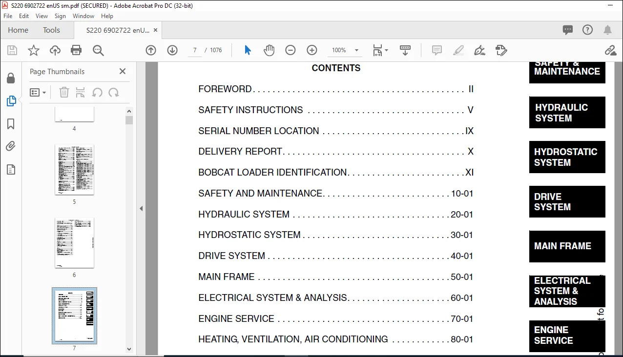
TABLE OF CONTENTS:
Bobcat S220 Turbo S220 Turbo High Flow Service Manual 6902722 (6-12) – PDF DOWNLOAD
MAINTENANCE SAFETY 3
ALPHABETICAL INDEX 5
CONTENTS 7
FOREWORD 8
SAFETY INSTRUCTIONS 11
Fire Prevention 13
SERIAL NUMBER LOCATION 15
Loader Serial Number 15
Engine Serial Number 15
DELIVERY REPORT 16
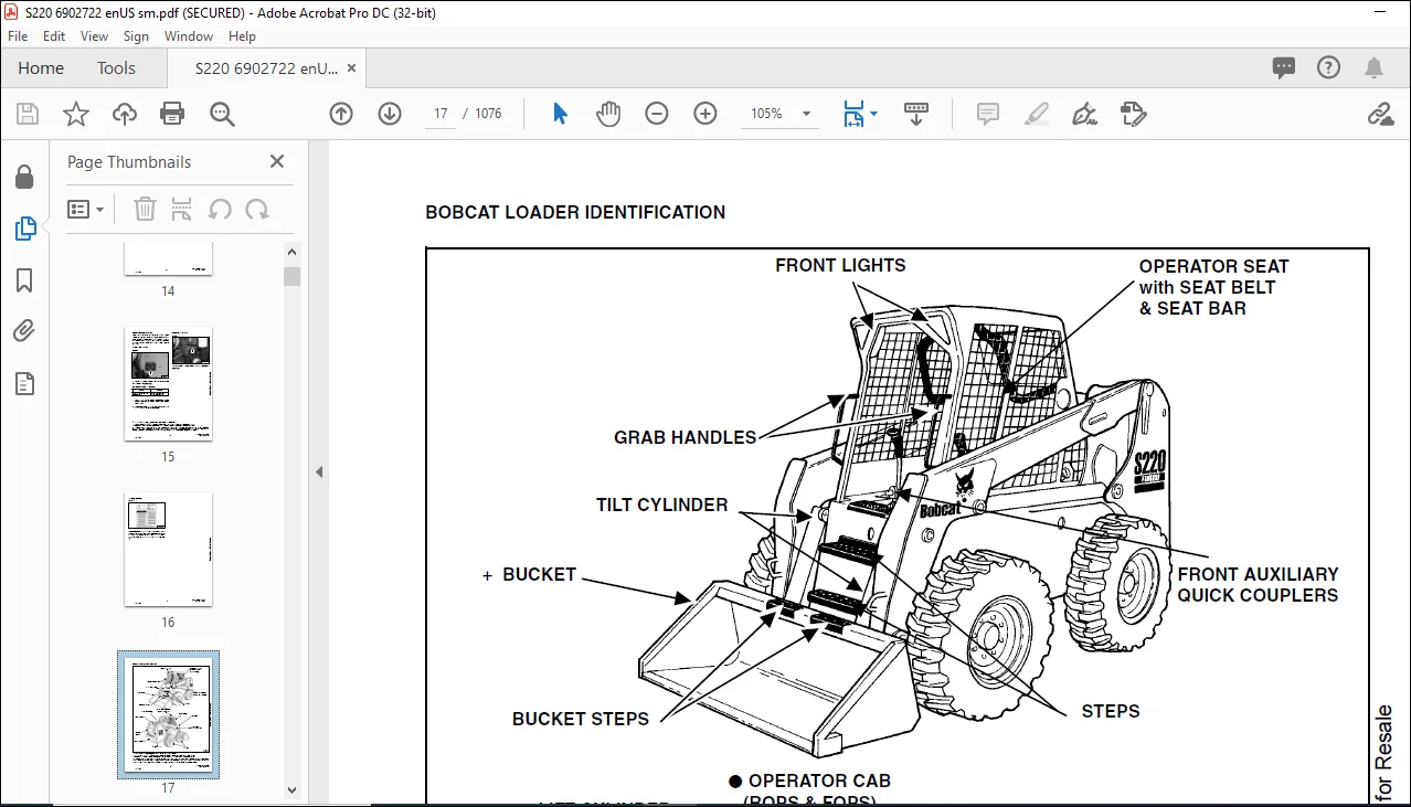
BOBCAT LOADER IDENTIFICATION 17
SAFETY AND MAINTENANCE 19
LIFTING AND BLOCKING THE LOADER 21
Procedure 21
LIFT ARM SUPPORT DEVICE 23
Engaging The Lift Arm Support Device 23
Disengaging The Lift Arm Support Device 24
OPERATOR CAB 25
Description 25
Raising The Operator Cab 25
Lowering The Operator Cab 26
Emergency Exit 26
TRANSPORTING THE BOBCAT LOADER 29
Procedure 29
TOWING THE LOADER 31
Procedure 31
REMOTE START 33
Procedure For Loader W/O Attachments Control Harness 33
Procedure For Loader With Attachments Control Harness 34
Procedure 35
SERVICE SCHEDULE 37
Chart 37
AIR CLEANER SERVICE 39
Replacing Filter Element 39
ENGINE COOLING SYSTEM 41
Cleaning Cooling System 41
Checking The Coolant Level 43
Adding The Coolant 44
FUEL SYSTEM 45
Fuel Specifications 45
Filling The Fuel Tank 45
Fuel Filter 45
Removing Air From The Fuel System 46
ENGINE LUBRICATION SYSTEM 47
Checking Engine Oil 47
Oil Chart 47
Replacing Oil And Filter 47
HYDRAULIC/HYDROSTATIC SYSTEM 49
Checking And Adding Fluid 49
Hydraulic Fluid Chart 49
Hydraulic/Hydrostatic Filter Replacement 50
Replacing Hydraulic Fluid And Case Drain Filters 51
FINAL DRIVE TRANSMISSION (CHAINCASE) 53
Checking And Adding Oil 53
Removing The Oil 53
FAN GEARBOX 55
Checking And Adding Oil 55
BOB-TACH 57
Inspection And Maintenance 57
POWER BOB-TACH 59
Inspection And Maintenance 59
LUBRICATING THE LOADER 61
Procedure 61
TIRE MAINTENANCE 63
Wheel Nuts 63
Tire Rotation 63
Tire Mounting 63
HYDRAULIC SYSTEM 65
HYDRAULIC/HYDROSTATIC SCHEMATICS 71
HYDRAULIC SYSTEM INFORMATION 103
Troubleshooting 107
Tightening Procedure 108
CYLINDER (LIFT) 109
Checking 109
Removal And Installation 109
Parts Identification 111
Disassembly 112
Assembly 113
CYLINDER (TILT) 117
Checking 117
Removal And Installation 117
Base Pin Removal And Installation 119
Parts Identification 120
Disassembly 121
Assembly 122
CYLINDER (POWER BOB-TACH) 125
Checking 125
Removal And Installation 126
Parts Identification 127
Disassembly 128
Assembly 129
MAIN RELIEF VALVE 133
Checking Main Relief 133
Adjustment 135
Removal And Installation 136
MAIN RELIEF VALVE (ACS) 137
Checking The Main Relief Valve At Front Aux Hyd 137
Removal And Installation 138
Adjustment 139
MAIN RELIEF VALVE (Selectable JOYSTICK Control) (Sjc) 141
Checking The Main Relief Valve At Front Auxiliary Hydraulics 141
Removal and Installation 142
Adjustment 143
HYDRAULIC CONTROL VALVE (2 PIECE CASTING) (FOOT CONTROL) 145
Identification 145
Removal And Installation 145
BICS™ Valve, Removal And Installation 149
BICS™ Valve, Lift Arm By-Pass Orifice Removal And Installation 151
BICS™ Valve, Check Valve Removal And Installation 152
Backslide, Lock Valve Removal And Installation 153
BICS™ Valve, Solenoid Removal And Installation 154
BICS™ Valve, Solenoid Testing 155
Identification Chart 156
Load Check Valve 157
Main Relief Valve 158
Port Relief Valve, Tilt Spool 158
Port Relief Valve, Lift Spool 159
Anti-Cavitation Valve/Port Relief Valve, Tilt Spool 159
Anti-Cavitation Valve, Lift Spool 160
Rubber Boot 160
Lift And Tilt Lock Block 161
Lift Spool And Detent Removal 162
Lift Spool And Detent Disassembly 164
Lift Spool And Detent Assembly 167
Lift Spool And Detent Installation 171
Tilt Spool Removal And Installation 172
Tilt Spool Disassembly And Assembly 173
Auxiliary Spool Removal And Installation 174
Auxiliary Plug Removal And Installation 176
Auxiliary Electric Solenoid Disassembly 177
Port-Auxiliary Section Removal And Installation 178
Cleaning And Inspection 178
HYDRAULIC CONTROL VALVE (2 PIECE CASTING) (ADVANCED CONTROL SYSTEM) (ACS) 179
Identification 179
Actuator Removal And Installation (In Loader) 180
Actuator Removal And Installation (Out Of Loader) 183
Removal And Installation 185
BICS™ Valve, Removal And Installation 189
BICS™ Valve, Lift Arm By-Pass Orifice Disassembly And Assembly 192
BICS™ Valve, Check Valve Disassembly And Assembly 193
BICS™ Valve, Lock Valve Disassembly And Assembly 194
BICS™ Valve, Solenoid Disassembly And Assembly 195
BICS™ Valve, Solenoid Testing 196
Identification Chart 197
Lift Base End Restrictor 198
Load Check Valve 199
Main Relief Valve 200
Port Relief Valve 202
Anti-Cavitation Valve/Port Relief Valve 203
Anti-Cavitation Valve 204
Lift Spool Removal 205
Lift Spool Removal And Installation 206
Lift and Tilt Spool Disassembly And Assembly 207
Auxiliary Spool Removal And Installation 208
Auxiliary Electric Solenoid Disassembly 209
Port-Auxiliary Section Disassembly 210
Cleaning And Inspection 210
HYDRAULIC CONTROL VALVE (2 PIECE CASTING) (selectable joystick control) (sjc) 211
Identification 211
Actuator Removal And Installation (In Loader) 212
Actuator Removal And Installation (Out Of Loader) 215
Removal And Installation 217
BICS™ Valve, Removal And Installation 221
BICS™ Valve, Lift Arm By-Pass Orifice Disassembly And Assembly 224
BICS™ Valve, Check Valve Disassembly And Assembly 225
BICS™ Valve, Lock Valve Disassembly And Assembly 226
BICS™ Valve, Solenoid Disassembly And Assembly 227
BICS™ Valve, Solenoid Testing 228
Identification Chart 229
Lift Base End Restrictor 230
Load Check Valve 230
Main Relief Valve 231
Port Relief Valve 232
Anti-Cavitation Valve/Port Relief Valve 233
Anti-Cavitation Valve 234
Lift Spool Removal 235
Lift Spool Removal And Installation 236
Lift and Tilt Spool Disassembly And Assembly 237
Auxiliary Spool Removal And Installation 238
Auxiliary Electric Solenoid Disassembly 239
Port-Auxiliary Section Disassembly 240
Cleaning And Inspection 240
HYDRAULIC CONTROL VALVE (1 PIECE CASTING) (FOOT CONTROL) 241
Removal And Installation 241
Identification Chart 246
BICS™ Valve, Lift Load Check Valve Removal And Installation 247
Load Check Valve Removal And Installation (Tilt & Auxiliary) 248
Anti-Cavitation Valve (Lift, Rod End) 248
Port Relief/Anti-Cavitation Valve (Lift, Base End) 249
Port Relief/Anti-Cavitation Valve (Tilt, Base End) 250
Port Relief/Anti-Cavitation Valve (Tilt, Rod End) 250
Port Relief Valve 251
Plug Removal 252
Rubber Boot Removal and Installation 253
End Cap/Spool Lock Block Removal and Installation 254
Lift Spool and Detent Removal and Installation 255
Auxiliary Spool Removal And Installation 267
Auxiliary Solenoid Disassembly and Assembly 269
BICS™ Valve Solenoid Disassembly And Assembly 270
BICS™ Valve, Lock Valve Removal And Installation 271
BICS™ Valve, Lift Arm By-Pass Orifice Disassembly And Assembly 273
Main Relief Valve 273
BICS™ Valve, Check Valve Removal and Installation 274
HYDRAULIC CONTROL VALVE (1 PIECE CASTING) (ADVANCED CONTROL SYSTEM) (ACS) 275
Identification 275
Removal And Installation 276
Actuator Removal And Installation (In Loader) 280
Identification Chart 285
BICS™ Valve, Lift Load Check Valve Removal And Installation 286
Load Check Valve Removal And Installation (Tilt & Auxiliary) 287
Anti-Cavitation Valve (Lift, Rod End) 287
Port Relief/Anti-Cavitation Valve (Lift, Base End) 288
Port Relief/Anti-Cavitation Valve (Tilt, Base End) 289
Port Relief/Anti-Cavitation Valve (Tilt, Rod End) 289
Port Relief Valve 290
Plug Removal 291
End Cap Block Removal And Installation 292
Lift Spool Removal And Installation 293
Auxiliary Spool Removal And Installation 299
Auxiliary Solenoid Disassembly And Assembly 301
BICS™ Valve Solenoid Disassembly And Assembly 302
BICS™ Valve, Lock Valve Removal And Installation 303
BICS™ Valve, Lift Arm By-Pass Orifice Disassembly And Assembly 305
Main Relief Valve 305
BICS™ Valve, Check Valve Removal And Installation 306
HYDRAULIC CONTROL VALVE (1 PIECE CASTING) (SELECTABLE JOYSTICK CONTROL) (SJC) 307
Identification 307
Removal And Installation 308
Actuator Removal And Installation (In Loader) 312
Identification Chart 317
BICS™ Valve, Lift Load Check Valve Removal And Installation 318
Load Check Valve Removal And Installation (Tilt & Auxiliary) 319
Anti-Cavitation Valve (Lift, Rod End) 319
Port Relief/Anti-Cavitation Valve (Lift, Base End) 320
Port Relief/Anti-Cavitation Valve (Tilt, Base End) 321
Port Relief/Anti-Cavitation Valve (Tilt, Rod End) 321
Port Relief Valve 322
Plug Removal 323
End Cap Block Removal And Installation 324
Lift Spool Removal And Installation 325
Auxiliary Spool Removal And Installation 331
Auxiliary Solenoid Disassembly And Assembly 333
BICS™ Valve Solenoid Disassembly And Assembly 334
BICS™ Valve, Lock Valve Removal And Installation 335
BICS™ Valve, Lift Arm By-Pass Orifice Disassembly And Assembly 337
Main Relief Valve 337
BICS™ Valve, Check Valve Removal And Installation 338
LIFT ARM BY-PASS CONTROL VALVE 339
Inspecting 339
Additional Inspection For Loaders W/Advanced Hand Controls 339
Removal And Installation 339
Disassembly And Assembly 340
HYDRAULIC PUMP 341
Check The Output Of The Hydraulic Pump 341
Removal And Installation 342
Identification 344
Disassembly And Assembly 345
HYDRAULIC PUMP (CHARGE) 353
Check The Output Of The Hydraulic Pump 353
Removal And Installation 356
Disassembly And Assembly 356
HYDRAULIC PUMP (HIGH FLOW) 357
Hydraulic Pump Test (30 GPM) 357
Hydraulic Pump Test (40 GPM) 358
Inline Hydraulic Pump Test (Standard) 359
Inline Hydraulic Pump Test (High Flow) (30 GPM And 40 GPM) 361
High Flow Relief Adjustment Procedure (30 GPM And 40 GPM) 363
High Flow Relief Valve Removal And Installation (30 GPM And 40 GPM) 365
Removal And Installation (30 GPM And 40 GPM) 366
Identification (30 GPM) (S/N 526214399 & Below) 368
Identification (40 GPM) (S/N 526214400 & Above) 369
Disassembly And Assembly (30 GPM And 40 GPM) 370
HYDRAULIC PUMP (SELECTABLE JOYSTICK CONTROL) (SJC) 383
Check The Output Of The Hydraulic Pump 383
Removal And Installation 384
Identification 386
Disassembly And Assembly 387
HYDRAULIC PUMP (HIGH FLOW) (SELECTABLE JOYSTICK CONTROL) (SJC) 393
Hydraulic Pump Test (30 GPM) 393
Hydraulic Pump Test (40 GPM) 394
Inline Hydraulic Pump Test (Standard) 395
Inline Hydraulic Pump Test (High Flow) (30 GPM and 40 GPM) 397
High Flow Relief Adjustment Procedure (30 GPM and 40 GPM) 399
High Flow Relief Valve Removal and Installation (30 GPM and 40 GPM) 401
Removal And Installation (30 GPM and 40 GPM) 403
Identification (30 GPM) (S/N 526214399 and Below) 405
Identification (40 GPM) (S/N 526214400 and Above) 406
Disassembly And Assembly (30 GPM and 40 GPM) 407
HYDRAULIC/HYDROSTATIC FILTER 417
Housing Removal And Installation 417
Mount Removal And Installation 418
HYDRAULIC FLUID RESERVOIR 419
Fluid Removal 419
Removal And Installation 419
Hydraulic Fluid Screen 422
BUCKET POSITION VALVE 425
Solenoid Removal And Installation 425
Solenoid Testing 425
Removal And Installation 426
Disassembly And Assembly 426
REAR AUXILIARY DIVERTER 429
Removal and Installation 429
Disassembly And Assembly 431
Solenoid Testing 436
Inspection 436
FRONT AUXILIARY HYDRAULIC COUPLER BLOCK 443
Removal and Installation 443
Disassembly And Assembly 443
HYDROSTATIC SYSTEM 445
HYDROSTATIC SYSTEM INFORMATION 447
Troubleshooting 447
Replenishing Valve Function 448
HYDROSTATIC MOTOR 449
Removal And Installation 449
Parts Identification 450
Disassembly 451
Inspection 453
Assembly 454
HYDROSTATIC MOTOR (TWO-SPEED) 459
Removal And Installation 459
Parts Identification 461
Disassembly 463
Inspection 470
Assembly 471
HYDROSTATIC MOTOR CARRIER 479
Removal and Installation 479
Parts Identification 481
Disassembly 482
Assembly 483
HYDROSTATIC MOTOR CARRIER (SELECTABLE JOYSTICK CONTROL) (SJC) 485
Removal And Installation 485
Parts Identification 486
Disassembly 487
Assembly 489
CHARGE PRESSURE 493
Testing 493
Removal And Installation 495
Setting Charge Pressure 496
HYDROSTATIC PUMP 497
Removal And Installation 497
Replenishing/High Pressure Relief Valve 499
Parts Identification (Right Half) 500
Parts Identification (Left Half) 502
Hydraulic Pump Removal And Installation 504
Pump Separation 504
Disassembly 505
Assembly 511
HYDROSTATIC PUMP (SELECTABLE JOYSTICK CONTROL) (SJC) 519
Pump Controller Removal And Installation 519
Hydrostatic Pump Calibration 522
Removal And Installation 527
Parts Identification (Right Half) 529
Parts Identification (Left Half) 531
System Check Relief Valves (High Pressure Relief, Charge Check & By-Pass Valve) 533
Charge Relief Valve 534
Pump Separation 536
Shaft Seal And Shaft Replacement 537
Shaft Seal And Shaft Installation 539
Charge Pump Removal 541
Charge Pump Inspection 543
Charge Pump Installation 544
Disassembly 546
Inspection 553
Assembly 557
Pump Neutral Adjustment 566
Pump Controller Neutral Adjustment 569
DRIVE BELT 573
Shield Removal And Installation 573
Adjustment 573
Replacement 573
Tensioner Pulley Removal And Installation 574
Tensioner Pulley Tension Spring 576
OIL COOLER (SEAL TO CONNECT) (STC) 577
Hydraulic Oil Cooler Removal And Installation 577
DRIVE SYSTEM 579
BRAKE 581
Disc Removal And Installation 581
BRAKE (TWO-SPEED) 585
Block Removal And Installation 585
Block Disassembly And Assembly 586
DRIVE COMPONENTS 591
Axle Seal Removal And Installation 591
Axle, Sprocket And Bearings Removal And Installation 593
Drive Chain Removal And Installation 598
CHAINCASE 599
Front Chaincase Cover Removal And Installation 599
Rear Chaincase Cover Removal And Installation 599
MAIN FRAME 601
SEAT BAR 605
Removal And Installation 605
Assembling Components 606
Compression Spring Disassembly And Assembly 607
OPERATOR CAB 609
Gas Cylinder Removal And Installation (Dual Gas Spring) 609
Gas Cylinder Removal And Installation (3rd Gas Spring) 611
Gas Cylinder Bracket Disassembly And Assembly 612
Removal And Installation 613
OPERATOR SEAT 617
Removal And Installation 617
Seat Belt Removal And Installation 617
OPERATOR SEAT (SUSPENSION) 619
Removal And Installation 619
Slide Rail Removal And Installation 620
Seat Belt Removal and Installation 620
Cushion Removal And Installation 621
Back Removal And Installation 622
Shock Removal And Installation 622
3-Point Seat Belt Removal And Installation 623
BOB-TACH 625
Removal And Installation 625
Bob-Tach Lever And Wedge 627
POWER BOB-TACH 629
Removal And Installation 629
Power Bob-Tach Lever And Wedge 631
Pivot Pin Bushing And Seal Replacement 633
LIFT ARMS 635
Removal And Installation 635
REAR GRILL 639
Removal And Installation 639
REAR DOOR 641
Removal And Installation 641
Striker Removal and Installation 642
Striker Disassembly and Assembly 642
Door Latch and Catch Adjustment 642
Latch Removal And Installation 643
FUEL TANK 645
Removal And Installation 645
Fuel Level Sender 646
CONTROL PEDALS 647
Removal And Installation 647
Pedal Adjustment 647
CONTROL PEDALS (ACS) 649
Foot Sensor Removal And Installation 649
Foot Pedal Removal And Installation 650
Foot Pedal Linkage Disassembly And Assembly 650
CONTROL PANEL (NON-ADJUSTABLE PINTLES) 651
Removal And Installation 651
Shock Removal And Installation 653
Shaft Removal And Installation 653
Shaft Disassembly And Assembly 653
Linkage Removal And Installation 655
Linkage Neutral Adjustment 658
CONTROL PANEL (ADJUSTABLE PINTLES) 665
Description 665
Removal And Installation 666
Shock Removal And Installation 668
Shaft Removal And Installation 668
Shaft Disassembly And Assembly 669
Linkage Removal And Installation 670
Pintle Arm Disassembly and Assembly 675
Linkage Neutral Adjustment 676
Linkage Travel Adjustment 680
CONTROL PANEL (SELECTABLE JOYSTICK CONTROL) (SJC) 685
Removal And Installation 685
CONTROL HANDLE 689
Lever Removal And Installation 689
Steering Lever Boot 689
CONTROL HANDLE (ADVANCED CONTROL SYSTEM) (ACS) SELECTABLE HAND/FOOT CONTROL 691
Components Identification 691
Handle Sensor Removal And Installation 691
Control Handle Removal And Installation 694
Control Handle Disassembly And Assembly 695
Control Lever Removal And Installation 696
Control Lever Boot 697
CONTROL HANDLE (SELECTABLE JOYSTICK CONTROL) (SJC) 699
Joystick Testing (Right & Left) 699
Joystick Removal (Right & Left) 700
Joystick Boot Removal (Right & Left) 701
Lever Assembly Removal (Right & Left) 701
INSIDE ACCESS PANEL 703
Removal And Installation (Left) 703
Removal And Installation (Right) 703
INSIDE ACCESS PANEL (SELECTABLE JOYSTICK CONTROL) (SJC) 705
Panel Removal (Right) 705
Panel Removal (Left) 708
ELECTRICAL SYSTEM & ANALYSIS 709
ELECTRICAL SCHEMATICS 713
ELECTRICAL SYSTEM INFORMATION 721
Troubleshooting 723
Description 724
Fuse Location 726
Relay Switch Location 726
Solenoid Test 727
BATTERY 729
Removal And Installation 729
Servicing The Electrical System 731
Using A Booster Battery (Jump Starting) 732
ALTERNATOR 733
Adjusting The Alternator Belt 733
Alternator Identification 733
Charging System Check 734
Alternator Voltage Test 735
Low Voltage Test 735
High Voltage Test 736
Removal And Installation 736
Rectifier Continuity (Diode) Test 737
Alternator Regulator Test 738
Disassembly 739
Stator Continuity Test 739
Stator Ground Test 739
Rotor Continuity Test 740
Rotor Ground Test 740
Assembly 740
STARTER 741
Checking 741
Removal And Installation 742
Parts Identification 743
Disassembly And Assembly 744
Inspection And Repair 747
No Load Test 750
INSTRUMENT PANEL 751
Left Panel 751
Right Panel (Standard) (With Key Switch) 752
Right Panel (Deluxe) (With Keyless Start) 753
Right Panel Setup Display Options (Deluxe) 755
Deluxe Panel Setup 756
Passwords (Deluxe) 756
Option And Field Accessory Panels (If Equipped) 758
Standard Panel Removal And Installation (Right Side) 759
Deluxe Panel Removal And Installation (Right Side) 760
Standard & Deluxe Panel Removal And Installation (Left Side) 761
Front Accessory Panel Removal And Installation 762
LIGHTS 763
Front Removal And Installation 763
Rear Removal And Installation 763
CONTROLLER (BOBCAT) 766
Identification Chart 766
Removal And Installation 768
CONTROLLER (SELECTABLE JOYSTICK CONTROL) (SJC) 769
Removal 769
Identification Chart 772
SPEED SENSOR (SELECTABLE JOYSTICK CONTROL) (SJC) 775
Testing 775
Removal 776
DIAGNOSTICS SERVICE CODES 779
Display 779
Number Codes List 780
BICS™ SYSTEM 785
Inspecting The BICS™ Controller (Engine STOPPED – Key ON) 785
Inspecting Deactivation Of The Auxiliary Hydraulics System (Engine STOPPED – Key ON) 785
Inspecting The Seat Bar Sensor (Engine RUNNING) 785
Inspecting The Traction Lock (Engine RUNNING) 785
Inspecting The Lift Arm By-Pass Control 786
Additional Inspection For Loaders With Advanced Controls System (ACS) or Selectable Joystick Control (SJC) 786
Troubleshooting 787
Troubleshooting Guide 788
SEAT BAR SENSOR 789
Troubleshooting Chart 789
Test 790
Removal And Installation 791
BICS™ Circuit Test 792
TRACTION LOCK 793
Troubleshooting 793
Removal And Installation (Single Speed) 794
Description Of The Control System (Two Speed) 795
Inspecting The Control System (Two Speed) 795
ADVANCED CONTROL SYSTEM (ACS) 797
Components Identification 797
Troubleshooting Guide 799
Controller, Connector And Wire Identification 800
ACS Controller Removal And Installation 801
Handle Sensor Connector 802
Switch Handle Removal 803
Switch Handle Installation 805
Actuators Disassembly And Assembly 808
Handle Lock Solenoid Removal And Installation 809
Handle Lock Solenoid Disassembly And Assembly 810
Handle Lock Solenoid Connector 810
Foot Sensor Disassembly And Assembly 811
Foot Sensor Connector 812
Foot Lock Solenoid Removal And Installation 813
Foot Lock Solenoid Connector 814
ELECTRICAL/HYDRAULIC CONTROLS REFERENCE 815
Controls Identification Chart 815
ELECTRICAL/HYDRAULIC CONTROLS REFERENCE (SELECTABLE JOYSTICK CONTROL) (SJC) 817
Controls Identification Chart 817
SERVICE PC (LAPTOP COMPUTER) 821
Connecting The Service PC To Remote Start Tool 821
CALIBRATION 823
Lift and Tilt Calibration Procedure (Selectable Joystick Control) (SJC) 823
Hydrostatic Pump Calibration (Selectable Joystick Control) (SJC) 825
Calibration Procedure (Advanced Control System) (ACS) 830
FLYWHEEL RPM SENSOR 833
Adjustment 833
ENGINE SERVICE 835
TROUBLESHOOTING 839
Chart 839
ENGINE SPEED CONTROL 841
Removal And Installation 841
Speed Control Cable 842
ENGINE SPEED CONTROL (SELECTABLE JOYSTICK CONTROL) (SJC) 845
Removal 845
Disassembly 847
Speed Control Cable 848
MUFFLER 849
Removal And Installation 849
AIR CLEANER 851
Housing Removal And Installation 851
RADIATOR 853
Removal And Installation 853
Mount Removal (Early Loaders) 855
Mount Removal (Later Loaders) 855
COOLING FAN 857
Drive Tension Pulley Removal And Installation 857
Gearbox/Blower Housing Removal And Installation 858
Blower Removal And Installation 859
Gearbox Parts Identification 861
Gearbox Disassembly 862
Gearbox Assembly 867
Gearbox, Checking Backlash 872
ENGINE 875
Removal And Installation 875
Mount Replacement 882
Removal And Installation Tools 883
FLYWHEEL AND HOUSING 885
Flywheel Removal And Installation 885
Ring Gear Removal And Installation 885
Flywheel Housing Removal And Installation 885
RECONDITIONING THE ENGINE 887
Engine Tools Identification Chart 887
Compression Pressure 892
Cylinder Head Clearance 892
Valve Cover, Injector Nozzle And Seal Removal And Installation 893
Checking Nozzle Injection Pressure 895
Nozzle Spraying Condition 896
Valve Seat Tightness 896
Rocker Arm And Push Rod Disassembly And Assembly 897
Valve Clearance 897
Cylinder Head And Tappet Disassembly And Assembly 898
Selecting Cylinder Head Gasket Disassembly And Assembly 899
Valve Disassembly And Assembly 901
Engine Timing (TDC) 901
Injection Pump Housing Removal 902
Injection Pump Governor Housing Removal And Installation 905
Injection Pump Governor Fork Lever Removal And Installation 907
Injection Pump Governor Lever Removal And Installation 907
Injection Pump Stop Lever Removal And Installation 908
Injection Pump Fuel Camshaft And Governor Weight Removal And Installation 908
Injection Pump Removal and Installation 910
Injection Pump Housing Installation 917
Injection Pump Timing 920
Fan Drive Pulley Disassembly And Assembly 922
Water Pump Disassembly And Assembly 923
Oil Cooler And Water Pipe Disassembly And Assembly 923
Gearcase Cover Disassembly And Assembly 924
Idle Gear And Camshaft Disassembly And Assembly 925
Oil Pan And Oil Strainer Disassembly And Assembly 925
Connecting Rod Cap Disassembly And Assembly 926
Piston Disassembly And Assembly 926
Piston Ring And Connecting Rod Disassembly And Assembly 927
Flywheel And Crankshaft Disassembly And Assembly 928
Bearing Case Cover Disassembly And Assembly 929
Flywheel Housing Disassembly And Assembly 930
Crankcase No 2 Disassembly And Assembly 930
Crankcase No 1 And No 2 Disassembly And Assembly 931
Crankshaft Disassembly And Assembly 931
Cylinder Head Surface Flatness 932
Cylinder Head Flaw 933
Valve Recessing 933
Valve Lapping 934
Clearance Between Valve Stem And Valve Guide 934
Replacing Valve Guide 935
Correcting Valve And Valve Seat 935
Free Length And Tilt Of Valve Spring 936
Valve Spring Setting Load 936
Oil Clearance Between Rocker Arm Shaft And Bearing 937
Oil Clearance Between Tappet And Tappet Guide Bore 937
Timing Gear Backlash 938
Idler Gear Side Clearance 938
Camshaft Side Clearance 939
Camshaft Alignment 939
Cam Height 939
Oil Clearance Between Idler Gear Shaft And Idler Gearing Bushing 940
Replacing Idler Gear Bushing 941
Piston Pin Bore I D 942
Oil Clearance Between Piston Pin And Small End Bushing 942
Replacing Small End Bushing 943
Clearance Between Piston Ring And Groove 943
Piston Ring Gap 944
Connecting Rod Alignment 944
Crankshaft Side Clearance 945
Crankshaft Alignment 946
Oil Clearance Between Crankpin And Crankpin Bearing 946
Oil Clearance Between Crankshaft Journal And Crankshaft Bearing 948
Replacing Crankshaft Sleeve 949
Cylinder Bore I D 949
Correcting Cylinder (Oversize +0 5 mm) 950
Engine Oil Pressure 950
Rotor Lobe Clearance 951
Clearance Between Outer Rotor And Pump Body 951
Clearance Between Rotor And Cover 951
Relief Valve 952
Thermostat Valve Opening Temperature 952
Radiator Water Leakage 952
Radiator Cap Air Leakage 953
Thermostat Assembly 953
Intake Air Heater 954
Air Cleaner, Intake Pipe, Inlet Pipe And Muffler 955
Oil Pipe 955
Turbocharger 956
HEATING, VENTILATION, AIR CONDITIONING 957
AIR CONDITIONING SYSTEM FLOW 960
Principals 960
Chart 961
COMPONENTS 963
Identification 963
SAFETY 967
Safety Equipment 967
REGULAR MAINTENANCE 969
Filter Elements Removal And Installation 969
Compressor Drive Belt Inspection 970
Cleaning The Condenser 971
BASIC TROUBLESHOOTING 973
Poor A/C Performance 973
Cleaning The A/C Evaporator Coil & Heater Coil 974
Compressor Drive Belt Inspection 974
Checking The Electrical System 975
Engine Coolant By-Passing The Heater Valve 983
Heater Valve Not Opening Or Closing 984
GENERAL AIR CONDITIONING SERVICE GUIDELINES 985
Compressor Oil 985
Compressor Oil Check 986
Component Replacement And Refrigeration Leaks 987
SYSTEM TROUBLESHOOTING CHART 989
Gauge Pressure Related Troubleshooting 990
Troubleshooting Tree 992
TEMPERATURE/PRESSURE 997
Chart 997
AIR CONDITIONING SERVICE 999
Chart 999
SYSTEM CHARGING AND RECLAMATION 1001
Reclamation Procedure 1001
Charging Procedure With A Manifold Gauge Set 1003
Charging Procedure 1004
COMPRESSOR 1007
Removal And Installation 1007
Compressor Clutch Disassembly 1008
CONDENSER 1013
Removal And Installation 1013
RECEIVER/DRIER 1015
Removal And Installation 1015
PRESSURE RELIEF VALVE 1017
Removal And Installation 1017
PRESSURE SWITCH 1019
Removal And Installation 1019
EVAPORATOR/HEATER UNIT 1021
Removal And Installation 1021
Disassembly And Assembly 1022
THERMOSTAT 1023
Removal And Installation 1023
EXPANSION VALVE 1025
Removal And Installation 1025
EVAPORATOR 1027
Removal And Installation 1027
HEATER COIL 1029
Removal And Installation With A/C 1029
BLOWER FAN 1031
Removal And Installation 1031
Disassembly And Assembly 1032
Wire Connector Removal And Installation 1034
HEATER VALVE 1037
Removal And Installation 1037
Disassembly And Assembly 1038
SPECIFICATIONS 1041
LOADER SPECIFICATIONS (S220) 1043
Machine Dimensions 1043
Performance 1044
Controls 1044
Engine 1044
Hydraulic System 1045
Electrical 1046
Drive System 1046
Capacities 1046
Tires 1046
ENGINE SPECIFICATIONS 1047
General 1047
Fuel System 1047
Valve And Valve Timing 1047
Valve Spring 1048
Piston And Piston Ring 1048
Connecting Rod 1048
Cylinder Head 1049
Crankshaft 1049
Cylinder Bore 1049
Oil Pump 1049
Rocker Arm 1050
Tappet 1050
Camshaft 1050
Thermostat 1050
Timing Gear 1051
Intake Air Heater 1051
Turbocharger Compressor Shaft 1051
TORQUE SPECIFICATIONS FOR BOLTS 1053
Torque For General SAE Bolts 1053
Torque For General Metric Bolts 1054
Torque For Kubota Metric Engine Bolts 1055
Tightening Torques For General Use Screws, Bolts And Nuts 1055
HYDRAULIC CONNECTION SPECIFICATIONS 1057
O-ring Face Seal Connection 1057
Straight Thread O-ring Fitting 1058
Tubelines And Hoses 1058
Flare Fitting 1058
O-ring Flare Fitting 1059
Port Seal Fitting 1061
HYDRAULIC FLUID SPECIFICATIONS 1063
Specifications 1063
CONVERSIONS 1065
Decimal And Millimeter Equivalents 1065
SMR 1067
Revision No: S220-1 1067
Revision No: S220-2 1069
Revision No: S220-3 1071
Revision No: S220-4 1073
Revision No: S220-5 1075
IMAGES PREVIEW OF THE MANUAL:
Contact us: [email protected]
PLEASE NOTE:
- This is the SAME manual used by the dealers to troubleshoot any faults in your vehicle. This can be yours in 2 minutes after the payment is made.
- Contact us at [email protected] should you have any queries before your purchase or that you need any other service / repair / parts operators manual.
S.V