Bobcat S250, S300 Skid-Steer Loader Service Manual 6904158 (3-09) – PDF DOWNLOAD
$36.95
Bobcat S250, S300 Skid-Steer Loader Service Manual 6904158 (3-09) – PDF DOWNLOAD
S/N 530911001 & Above
S/N 531011001 & Above
S/N 531111001 & Above
S/N 531211001 & Above
Description
Bobcat S250, S300 Skid-Steer Loader Service Manual 6904158 (3-09) – PDF DOWNLOAD
FILE DETAILS:
Bobcat S250, S300 Skid-Steer Loader Service Manual 6904158 (3-09) – PDF DOWNLOAD
Language : English
Pages : 1019
Downloadable : Yes
File Type : PDF
DESCRIPTION:
Bobcat S250, S300 Skid-Steer Loader Service Manual 6904158 (3-09) – PDF DOWNLOAD
S/N 530911001 & Above
S/N 531011001 & Above
S/N 531111001 & Above
S/N 531211001 & Above
FOREWORD:
This manual is for the Bobcat loader mechanic. It provides necessary servicing and adjustment procedures for the Bobcat loader and its component parts and systems. Refer to the Operation & Maintenance Manual for operating instructions, starting procedure, daily checks, etc.
A general inspection of the following items must be made after the loader has had service or repair:
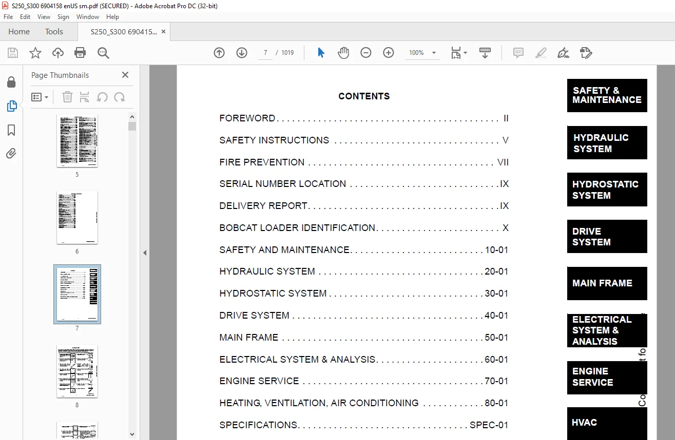
TABLE OF CONTENTS:
Bobcat S250, S300 Skid-Steer Loader Service Manual 6904158 (3-09) – PDF DOWNLOAD
MAINTENANCE SAFETY 3
ALPHABETICAL INDEX 5
CONTENTS 7
FOREWORD 8
SAFETY INSTRUCTIONS 11
FIRE PREVENTION 13
Maintenance 13
Operation 13
Electrical 13
Hydraulic System 13
Fueling 13
Starting 13
Spark Arrestor Exhaust System 13
Welding And Grinding 14
Fire Extinguishers 14
SERIAL NUMBER LOCATION 15
Loader Serial Number 15
Engine Serial Number 15
DELIVERY REPORT 15
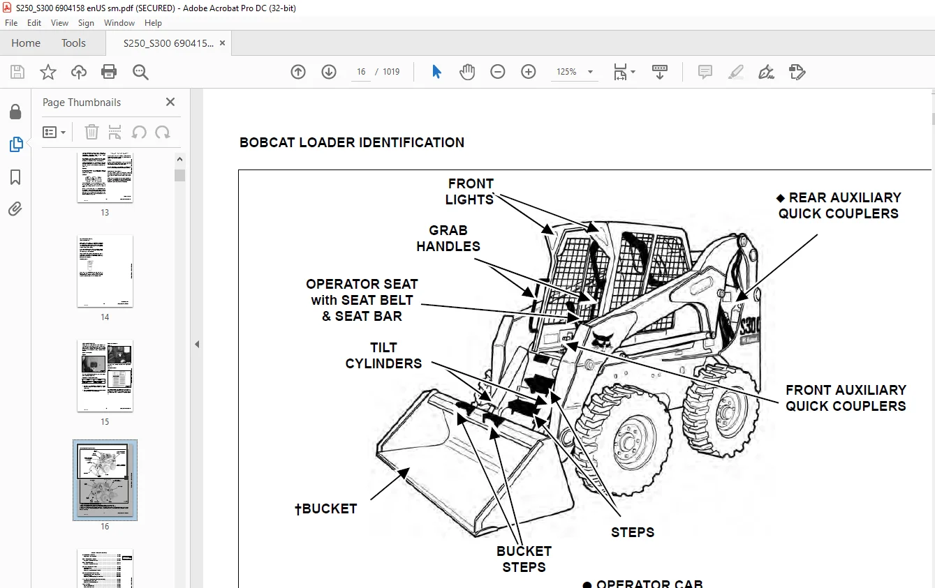
BOBCAT LOADER IDENTIFICATION 16
SAFETY AND MAINTENANCE 17
LIFTING AND BLOCKING THE LOADER 21
Procedure 21
LIFT ARM SUPPORT DEVICE 23
Installing 23
Removing 24
OPERATOR CAB 25
Description 25
Raising 25
Lowering 27
Cab Door Sensor 28
Special Applications Kit Inspection And Maintenance 28
TRANSPORTING THE LOADER ON A TRAILER 29
Loading And Unloading 29
Fastening 29
TOWING THE LOADER 31
Procedure 31
REMOTE START TOOL KIT-MEL1563 33
Remote Start Tool – MEL1563 33
Service Tool Harness Control – MEL1565 34
Service Tool Harness Communicator – MEL1566 35
Remote Start Procedure 36
REMOTE START TOOL (SERVICE TOOL) KIT – 6689779 39
Description 39
Remote Start Tool (Service Tool) – 6689778 40
Loader Service Tool Harness – 6689747 41
Computer Service Tool Harness – 6689746 42
Remote Start Procedure 43
SERVICE SCHEDULE 47
Chart 47
AIR CLEANER SERVICE 49
Replacing Filter Elements 49
ENGINE COOLING SYSTEM 51
Cleaning 51
Removing And Replacing Coolant 52
Checking Level 52
FUEL SYSTEM 53
Fuel Specifications 53
Biodiesel Blend Fuel 53
Filling The Fuel Tank 54
Fuel Filter 54
Removing Air From The Fuel System 55
ENGINE LUBRICATION SYSTEM 57
Checking And Adding Engine Oil 57
Engine Oil Chart 57
Removing And Replacing Oil And Filter 58
HYDRAULIC / HYDROSTATIC SYSTEM 59
Checking And Adding Fluid 59
Hydraulic / Hydrostatic Fluid Chart 59
Removing And Replacing Hydraulic Fluid 60
Removing And Replacing Hydraulic / Hydrostatic Filter 61
Removing And Replacing Case Drain Filters 62
Removing And Replacing Hydraulic Charge Filter 63
Breather Cap 64
FINAL DRIVE TRANSMISSION (CHAINCASE) 65
Checking And Adding Oil 65
Removing And Replacing Oil 65
BOB-TACH (HAND LEVER) 67
Inspection And Maintenance 67
BOB-TACH (POWER) 69
Inspection And Maintenance 69
LUBRICATING THE LOADER 71
Lubrication Locations 71
TIRE MAINTENANCE 73
Wheel Nuts 73
Rotating 73
Mounting 74
SPARK ARRESTOR MUFFLER 75
Cleaning Procedure 75
PIVOT PINS 77
Inspection And Maintenance 77
LOADER STORAGE AND RETURN TO SERVICE 79
Storage 79
Return to Service 79
STOPPING THE ENGINE AND LEAVING THE LOADER 81
Procedure 81
Emergency Exit 82
HYDRAULIC SYSTEM 83
HYDRAULIC / HYDROSTATIC SCHEMATICS 89
HYDRAULIC SYSTEM INFORMATION 121
Glossary Of Hydraulic / Hydrostatic Symbols 121
Troubleshooting 125
CYLINDER (LIFT) 127
Testing 127
Removal And Installation 128
Parts Identification 130
Disassembly 131
Assembly 133
CYLINDER (TILT) 135
Testing 135
Removal And Installation 136
Base End Pivot Pin Removal And Installation 138
Parts Identification 139
Disassembly 140
Assembly 142
CYLINDER (BOB-TACH) 145
Testing 145
Removal And Installation 146
Parts Identification 147
Disassembly 148
Assembly 149
MAIN RELIEF VALVE 153
Description 153
Testing 154
Adjusting 156
Removal And Installation 157
HYDRAULIC CONTROL VALVE (STANDARD) 159
Description 159
Removal And Installation 160
Identification Chart 164
Mount Bracket Removal And Installation 165
Lift Load Check Valve Removal And Installation 165
Load Check Valve Removal And Installation (Tilt & Auxiliary) 166
Anti-Cavitation Valve Removal And Installation (Lift, Rod End) 166
Port Relief / Anti-Cavitation Valve Removal And Installation (Lift, Base End) 167
Port Relief / Anti-Cavitation Valve Removal And Installation (Tilt, Base End) 168
Port Relief / Anti-Cavitation Valve Removal And Installation (Tilt, Rod End) 168
Port Relief Valve Removal And Installation 169
Plug Removal And Installation 170
Rubber Boot Removal And Installation 171
End Cap Block Removal And Installation 172
Lift Spool And Detent Removal And Installation 173
Tilt Spool Removal And Installation 183
Auxiliary Spool Removal And Installation 185
Auxiliary Solenoid Removal And Installation 187
Solenoid Removal And Installation 188
Lock Valve Removal And Installation 189
Lift Arm By-Pass Orifice Removal And Installation 191
Main Relief Valve Removal And Installation 191
Check Valve Removal And Installation 192
HYDRAULIC CONTROL VALVE (ACS) OR (SJC) 193
Description 193
Removal And Installation 194
Actuator Removal And Installation (In Loader) 198
Actuator Removal And Installation (Out Of Loader) 200
Identification Chart 203
Mount Bracket Removal And Installation 204
Lift Load Check Valve Removal And Installation 204
Load Check Valve Removal And Installation (Tilt & Auxiliary) 205
Anti-Cavitation Valve Removal And Installation (Lift, Rod End) 205
Port Relief / Anti-Cavitation Valve Removal And Installation (Lift, Base End) 206
Port Relief / Anti-Cavitation Valve Removal And Installation (Tilt, Base End) 207
Port Relief / Anti-Cavitation Valve Removal And Installation (Tilt, Rod End) 207
Port Relief Valve Removal And Installation 208
Plug Removal And Installation 209
End Cap Block Removal And Installation 210
Lift Spool And Detent Removal And Installation 211
Tilt Spool Removal And Installation 216
Auxiliary Spool Removal And Installation 218
Auxiliary Solenoid Removal And Installation 220
Solenoid Removal And Installation 221
Lock Valve Removal And Installation 222
Lift Arm By-Pass Orifice Removal And Installation 224
Main Relief Valve Removal And Installation 224
Check Valve Removal And Installation 225
LIFT ARM BYPASS CONTROL VALVE 227
Description 227
Testing 228
Removal And Installation 229
Disassembly And Assembly 230
HYDRAULIC PUMP (STANDARD) 231
Description 231
Pump Test at Quick Couplers 232
Direct Pump Test (Standard Section) 233
Direct Pump Test (Charge Section) 235
Removal And Installation 239
Hydraulic Pump Start Up 241
Parts Identification 242
Disassembly And Assembly 243
HYDRAULIC PUMP (STANDARD) (HIGH FLOW) 245
Description 245
Pump Test At Quick Couplers 246
Direct Pump Test (Standard Section) 247
Direct Pump Test (Charge Section) 249
Direct Pump Test (High Flow Section) 253
High Flow Relief Valve Adjustment 255
High Flow Relief Valve Removal And Installation 258
Solenoid Removal And Installation 259
Removal And Installation 260
Hydraulic Pump Start Up 262
Parts Identification 264
Disassembly And Assembly 265
HYDRAULIC PUMP (SJC) 267
Description 267
Pump Test At Quick Couplers 268
Direct Pump Test (Standard Section) 269
Direct Pump Test (Charge Section) 271
Removal And Installation 275
Hydraulic Pump Start Up 277
Parts Identification 278
Disassembly And Assembly 279
HYDRAULIC PUMP (SJC) (HIGH FLOW) 281
Description 281
Pump Test At Quick Couplers 282
Direct Pump Test (Standard Section) 283
Direct Pump Test (Charge Section) 285
Direct Pump Test (High Flow Section) 289
High Flow Relief Valve Adjustment 291
High Flow Relief Valve Removal And Installation 294
Solenoid Removal And Installation 295
Removal And Installation 296
Hydraulic Pump Start Up 298
Parts Identification 300
Disassembly And Assembly 301
HYDRAULIC/HYDROSTATIC FILTERS 303
Description 303
Housing Removal And Installation 303
Charge Filter Housing Removal And Installation 305
HYDRAULIC FLUID RESERVOIR 307
Description 307
Removal And Installation 307
Hydraulic Fluid Screen 310
OIL COOLER 311
Description 311
Removal And Installation 311
BUCKET POSITION VALVE 313
Description 313
Solenoid Removal And Installation 314
Solenoid Testing 315
Removal And Installation 315
Disassembly And Assembly 316
REAR AUXILIARY DIVERTER VALVE 319
Description 319
Solenoid Testing 319
Removal And Installation 320
Disassembly And Assembly 322
BOB-TACH (POWER) BLOCK 329
Description 329
Removal And Installation 329
Disassembly And Assembly 331
FRONT AUXILIARY HYDRAULIC COUPLER BLOCK 335
Description 335
Removal and Installation 335
Disassembly And Assembly 336
HYDROSTATIC SYSTEM 339
HYDROSTATIC SYSTEM INFORMATION 341
Troubleshooting 341
Description 342
HYDROSTATIC MOTOR 343
Description 343
Removal And Installation 344
Parts Identification 346
Disassembly And Assembly 347
HYDROSTATIC MOTOR (TWO-SPEED) 351
Description 351
Removal And Installation 352
Parts Identification 355
Disassembly 357
Assembly 363
HYDROSTATIC MOTOR CARRIER 367
Description 367
Removal and Installation 368
Parts Identification 369
Disassembly 370
Assembly 371
HYDROSTATIC MOTOR CARRIER (SJC) 373
Description 373
Removal and Installation 374
Parts Identification 375
Disassembly 376
Assembly 378
CHARGE PRESSURE 381
Description 381
Testing 382
Sender Removal And Installation 384
Adjusting 385
HYDROSTATIC PUMP 387
Description 387
Removal And Installation 388
Hydrostatic Pump Start Up 390
Replenishing / High Pressure Relief Valve Removal And Installation 391
Parts Identification (Left Half) 392
Parts Identification (Right Half) 393
Disassembly 394
Assembly 401
HYDROSTATIC PUMP (SJC) 407
Description 407
Hydraulic Controller Removal And Installation 408
Removal And Installation 410
Hydrostatic Pump Start Up 412
Parts Identification 413
High Pressure Relief And By-Pass Valve 414
Charge Relief Valve 415
Disassembly And Assembly 416
Mechanical Neutral Adjustment 433
Hydraulic Controller Neutral Adjustment 436
DRIVE BELT 439
Description 439
Drive Belt Shield Removal And Installation 439
Adjusting 440
Belt Removal And Installation 440
Tensioner Pulley Removal And Installation 441
Tensioner Pulley Tension Spring Removal And Installation 443
CASE DRAIN FILTER 445
Description 445
Disassembly And Assembly 445
DRIVE SYSTEM 447
BRAKE (S/N 530917348 & BELOW, 531012023 & BELOW, 531116712 & BELOW AND 531211918 & BELOW) 449
Description 449
Disc Removal And Installation 450
BRAKE (S/N 530917349 & ABOVE, 531012024 & ABOVE, 531116713 & ABOVE AND 531211919 & ABOVE) 453
Description 453
Disc Removal And Installation 454
BRAKE (TWO-SPEED) 457
Description 457
Block Removal And Installation 458
Block Disassembly And Assembly 460
DRIVE COMPONENTS 465
Description 465
Axle Seal Removal And Installation 466
Axle, Sprocket And Bearings Removal And Installation 468
Chain Removal And Installation 473
CHAINCASE 475
Description 475
Front Cover Removal And Installation 475
Center Cover Removal And Installation 476
Rear Cover Removal And Installation 477
MAIN FRAME 479
SEAT BAR 483
Description 483
Removal And Installation 483
Disassembly And Assembly 485
Compression Spring Disassembly And Assembly 486
OPERATOR CAB 487
Gas Cylinder Removal And Installation 487
Gas Cylinder Bracket Disassembly And Assembly 489
Removal And Installation 490
OPERATOR SEAT 493
Removal And Installation 493
Seat Belt Removal And Installation 493
OPERATOR SEAT (SUSPENSION) 495
Removal And Installation 495
Slide Rail Removal And Installation 496
Seat Belt Removal And Installation 496
Cushion Removal And Installation 497
Back Removal And Installation 498
Shock Removal And Installation 498
3-Point Seat Belt Removal And Installation 499
BOB-TACH (HAND LEVER) 501
Description 501
Removal And Installation 501
Lever And Wedge Disassembly And Assembly 504
Pivot Pin Bushing And Seal Removal And Installation 505
BOB-TACH (POWER – OPTION) 507
Description 507
Removal And Installation 507
Lever And Wedge Disassembly And Assembly 510
Pivot Pin Bushing And Seal Removal And Installation 512
LIFT ARMS 513
Stabilizer Bar Removal And Installation 513
Link Removal And Installation 514
Removal And Installation 515
REAR GRILL 519
Removal And Installation 519
REAR DOOR 521
Removal And Installation 521
Striker Removal And Installation 522
Striker Disassembly And Assembly 522
Striker (Adjusting) 523
Latch Removal And Installation 524
FUEL TANK 525
Removal And Installation 525
Fuel Level Sender Removal And Installation 527
Fuel Fill Screen Removal And Installation 527
CONTROL PEDALS AND LINKAGES 529
Description 529
Pedal Removal And Installation 530
Linkage Removal And Installation 531
Pedal (Adjusting) 532
CONTROL PEDALS (ACS) 533
Description 533
Foot Sensor Removal And Installation 534
Foot Pedal Removal And Installation 535
Foot Pedal Linkage Disassembly And Assembly 535
CONTROL PANEL (S/N 531011925 & BELOW, 530917134 & BELOW, 531116513 & BELOW, AND 531211869 & BELOW) 537
Description 537
Removal And Installation 538
Shock Removal And Installation 540
Shaft Removal And Installation 540
Shaft Disassembly And Assembly 541
Linkage Removal And Installation 542
Pintle Arm Disassembly and Assembly 546
Linkage Neutral (Adjusting) 547
Linkage Travel (Adjusting) 551
CONTROL PANEL (S/N 531011926 & ABOVE, 530917135 & ABOVE, 531116514 & ABOVE, AND 531211870 & ABOVE) 555
Description 555
Removal And Installation 556
Shock Removal And Installation 558
Shaft Removal And Installation 559
Linkage Removal And Installation 560
Pintle Arm Disassembly and Assembly 564
Linkage Neutral (Adjusting) 565
Linkage Travel (Adjusting) 569
CONTROL PANEL (S/N 531011925 & BELOW, 530917134 & BELOW, 531116513 & BELOW, AND 531211869 & BELOW) (SJC) 573
Description 573
Removal And Installation 574
CONTROL PANEL (S/N 531011926 & ABOVE, 530917135 & ABOVE, 531116514 & ABOVE, AND 531211870 & ABOVE) (SJC) 577
Description 577
Removal And Installation 578
CONTROL HANDLE / LEVER 581
Description 581
Lever Removal And Installation 581
Boot Removal And Installation 582
CONTROL HANDLE / LEVER (ACS) 583
Description 583
Handle Sensor Removal And Installation 583
Handle Removal And Installation 586
Handle Disassembly And Assembly 587
Lever Removal And Installation 588
Boot Removal And Installation 589
JOYSTICK CONTROL 591
Description (Earlier Models And Later Models) 591
Testing (Earlier Models And Later Models) 592
Removal And Installation (Earlier Models) 593
Removal And Installation (Later Models) 594
Boot Removal And Installation (Earlier Models) 595
Joystick Mount Removal And Installation (Earlier Models) 595
Joystick Mount Removal And Installation (Earlier Models) (Cont’d) 596
Joystick Mount Removal And Installation (Later Models) 596
ACCESS PANEL (INSIDE) 597
Removal And Installation (Left) 597
Removal And Installation (Right) 597
ACCESS PANEL (INSIDE) (SJC) 599
Removal And Installation (Left) 599
Removal And Installation (Right) 600
WINDOW (REAR) 603
Removal 603
Installation 603
WINDOW (TOP) 605
Removal And Installation 605
WINDOW (SIDE) 607
Removal And Installation 607
WINDOW (FRONT DOOR) 609
Removal (Standard Window) 609
Installation (Standard Window) 610
Removal And Installation (Special Applications Window) 612
CAB DOOR 613
Description 613
Removal And Installation 613
Aligning 614
Adjusting 615
Checking Operation 615
ELECTRICAL SYSTEM & ANALYSIS 617
ELECTRICAL SCHEMATICS 621
ELECTRICAL SYSTEM INFORMATION 634
Glossary Of Electrical Symbols 634
Cab Harness Connectors 637
Mainframe Harness Connectors 638
Troubleshooting 639
Description 640
Fuse And Relay Location / Identification 641
Solenoid Testing 642
BATTERY 644
Servicing 644
Using A Booster Battery (Jump Starting) 644
Removal And Installation 646
ALTERNATOR 648
Belt Adjustment 648
Belt Replacement 648
Charging System Inspection 649
Alternator Voltage Testing 650
Low Voltage Testing 650
High Voltage Testing 651
Removal And Installation 652
Parts Identification 653
STARTER 654
Testing 654
Removal And Installation 655
Parts Identification 656
INSTRUMENT PANELS 658
Left Panel 658
Right Panel (Key Switch) 659
Right Panel (Keyless) 660
Side And Front Panels 662
Removal And Installation (Left And Right) 663
Bulb Removal And Installation (Left Only) 666
Key Switch Removal And Installation 667
Alarm Removal And Installation 668
Front Panel Removal And Installation 668
LIGHTS 670
Front Removal And Installation 670
Rear Removal And Installation 671
Cab Light Removal And Installation 671
BOBCAT CONTROLLER (MAIN) 672
Description 672
Connector Identification 673
Removal And Installation 675
BOBCAT CONTROLLER (ACS) 676
Description 676
Connector And Wire Identification 677
Removal And Installation 678
BOBCAT CONTROLLER (SJC) (DRIVE) 680
Description 680
Connector Identification 681
Removal And Installation 683
SPEED SENSOR (SJC) 684
Description 684
Testing 685
Removal And Installation 686
DIAGNOSTIC SERVICE CODES 688
Viewing Service Codes (Key Switch) 688
Viewing Service Codes (Keyless) 688
Service Codes List 689
BOBCAT INTERLOCK CONTROL SYSTEM (BICS) 694
Description 694
Inspecting The BICS Controller (Engine Stopped – Key ON) 695
Inspecting Deactivation Of The Auxiliary Hydraulics System (Engine STOPPED – Key ON) 695
Inspecting The Seat Bar Sensor (Engine RUNNING) 695
Inspecting The Traction Lock (Engine RUNNING) 695
Inspecting The Lift Arm Bypass Control 695
Inspecting Deactivation Of Lift And Tilt Functions (ACS and SJC) 695
Troubleshooting 696
Troubleshooting Chart 697
SEAT BAR SENSOR 698
Description 698
Troubleshooting 699
Testing 700
Removal And Installation 701
Bobcat Interlock Control System (BICS) Circuit Test 702
TRACTION LOCK 704
Description 704
Troubleshooting 705
Removal And Installation (Single Speed) 706
Inspecting (Single and Two Speed) 710
CONTROL SYSTEM (ACS) 712
Description 712
Troubleshooting Chart 713
Handle Sensor Connector Disassembly And Assembly 714
Switch Handle Removal 715
Switch Handle Installation 717
Actuator Connector Disassembly And Assembly 720
Handle Lock Solenoid Removal And Installation 721
Handle Lock Solenoid Disassembly And Assembly 722
Foot Sensor Disassembly And Assembly 722
Foot Lock Solenoid Removal And Installation 723
ELECTRICAL / HYDRAULIC CONTROLS 724
Identification Chart 724
ELECTRICAL / HYDRAULIC CONTROLS (SJC) 726
Identification Chart 726
SERVICE PC (LAPTOP COMPUTER) 730
Connecting Remote Start Tool 730
Connecting Remote Start Tool (Service Tool) 730
CALIBRATION 732
Description 732
Actuator Testing 732
Lift And Tilt Calibration (ACS) 734
Lift And Tilt Calibration (SJC) 736
Hydrostatic Pump Calibration (SJC) 738
STEERING DRIFT COMPENSATION 744
Description 744
Selecting And Adjusting 744
Exiting And Saving 745
FLYWHEEL RPM SENSOR 746
Description 746
Adjustment 747
CONTROL PANEL SETUP 748
Right Panel Setup (Keyless) 748
Attachment Control Information (Keyless) 749
PASSWORD SETUP (IF EQUIPPED WITH KEYLESS START) 750
Password Description 750
Changing The Owner Password 750
Changing The User Passwords 751
Password Lockout Feature 751
MAINTENANCE CLOCK 752
Description 752
Setup 753
Reset 757
BACK-UP ALARM SYSTEM 758
Description 758
Inspecting 758
Adjusting Switch Position 759
Troubleshooting (Standard And ACS) 760
Troubleshooting (Joystick) 761
Alarm Removal And Installation 762
Switch Removal And Installation 762
ENGINE SERVICE 764
ENGINE INFORMATION 768
Description 768
Specifications 769
Torque Values 773
Troubleshooting 774
Engine Removal And Installation 776
Engine Mount Replacement 785
Compression -Checking 786
ENGINE SPEED CONTROL 788
Removal And Installation 788
Cable Removal And Installation 789
ENGINE SPEED CONTROL (SJC) 790
Removal And Installation 790
Disassembly And Assembly 792
Speed Control Cable Removal And Installation 793
MUFFLER 794
Removal And Installation 794
AIR CLEANER 796
Housing Removal And Installation 796
ENGINE COOLING SYSTEM 798
Radiator Removal And Installation (S/N 530915315 & Below, 531011742 & Below, 531115050 & Below, 531211660 & Below) 798
Radiator Removal And Installation (S/N 530915316 & Above, 531011743 & Above, 531115051 & Above, 531211661 & Above) 800
Radiator Mount Removal And Installation 802
Hydraulic Fan Motor Description (S/N 530915315 & Below, 531011742 & Below, 531115050 & Below, 531211660 & Below) 803
Blower Housing Removal And Installation (S/N 530915315 & Below, 531011742 & Below, 531115050 & Below, 531211660 & Below) 803
Fan Removal And Installation (S/N 530915315 & Below, 531011742 & Below, 531115050 & Below, 531211660 & Below) 805
Hydraulic Fan Motor Removal And Installation (S/N 530915315 & Below, 531011742 & Below, 531115050 & Below, 531211660 & Below) 806
Hydraulic Fan Motor Disassembly And Assembly (S/ N 530915315 & Below, 531011742 & Below, 531115050 & Below, 531211660 & Below) 806
Hydraulic Fan Motor Description (S/N 530915316 – 530940000, 531011743 – 531040000, 531115051 – 531140000, 531211661 – 531240000) 807
Axial Fan Housing Removal And Installation (S/N 530915316 – 530940000, 531011743 – 531040000, 531115051 – 531140000, & 531211661 – 531240000) 807
Axial Fan Removal And Installation (S/N 530915316 – 530940000, 531011743 – 531040000, 531115051 – 531140000, & 531211661 – 531240000) 809
Hydraulic Fan Motor Removal And Installation (S/N 530915316 – 530940000, 531011743 – 531040000, 531115051 – 531140000, & 531211661 – 531240000) 811
Hydraulic Fan Motor Disassembly And Assembly (S/ N 530915316 – 530940000, 531011743 – 531040000, 531115051 – 531140000, & 531211661 – 531240000) 811
Hydraulic Fan Motor Description (S/N 530940001 & Above, 531040001 & Above, 531140001 & Above, 531240001 & Above) 812
Axial Fan Housing Removal And Installation (S/N 530940001 & Above, 531040001 & Above, 531140001 & Above, 531240001 & Above) 812
Axial Fan Removal And Installation (S/N 530940001 & Above, 531040001 & Above, 531140001 & Above, 531240001 & Above) 815
Hydraulic Fan Motor Removal And Installation (S/N 530940001 & Above, 531040001 & Above, 531140001 & Above, 531240001 & Above) 816
Hydraulic Fan Motor Disassembly And Assembly (S/ N 530940001 & Above, 531040001 & Above, 531140001 & Above, 531240001 & Above) 817
Water Pump Removal And Installation 818
Water Pump Disassembly And Assembly 819
Thermostat Housing Removal And Installation 819
LUBRICATION SYSTEM 822
Oil Pan Removal And Installation 822
Oil Pump Removal And Installation 823
Oil Pump Inspection 823
Oil Filter Cooler Removal And Installation 826
Engine Oil Pressure – Testing 827
FUEL SYSTEM 828
Fuel Camshaft Removal And Installation 828
Injection Pump Governor Housing Removal And Installation 830
Injection Pump Governor Housing Disassembly And Assembly 832
Fuel Shutoff Solenoid – Checking 834
Fuel Shutoff Solenoid – Removal And Installation 834
Fuel Injection Pump Removal And Installation 835
Fuel Injection Pump Housing Removal 843
Fuel Injection Pump Housing Installation 847
Injection Pump Timing 850
Fuel Injector Removal and Installation 853
Fuel Injector Nozzle Pressure – Checking 854
Nozzle Spraying Condition 855
Valve Seat Tightness 855
CYLINDER HEAD 856
Intake Air Heater – Testing 856
Intake Air Heater Removal And Installation 856
Valve Clearance Adjustment 857
Valve Timing – Checking 858
Cylinder Head Removal And Installation 859
Cylinder Head Disassembly And Assembly 862
Cylinder Head – Servicing 862
Cylinder Head Top Clearance 863
Valve Guide – Checking 864
Reconditioning The Valve And Valve Seat 866
Valve Spring 868
Valve Tappets 869
Rocker Arm And Shaft – Checking 870
CRANKSHAFT AND PISTONS 872
Piston And Connecting Rod Removal And Installation 872
Piston And Connecting Rod – Servicing 874
Cylinder Bore Checking 879
Connecting Rod Alignment 880
Crankshaft Gear Removal And Installation 880
Crankshaft And Bearings Removal and Installation 881
Crankshaft And Bearings – Servicing 885
CAMSHAFT AND TIMING GEArS 892
Timing Gearcase Cover Removal And Installation 892
Timing Gears Backlash – Checking 893
Camshaft – Servicing 894
Idle Gear And Shaft Removal And Installation 896
Idler Gear And Shaft – Servicing 897
TURBOCHARGER 900
Description 900
Testing 900
Removal And Installation 901
FLYWHEEL AND HOUSING 902
Flywheel Removal And Installation 902
Ring Gear Removal And Installation 902
Housing Removal And Installation 903
HEATING, VENTILATION, AIR CONDITIONING 904
AIR CONDITIONING SYSTEM FLOW 907
Description 907
Chart 908
Components 909
Safety Equipment 912
REGULAR MAINTENANCE 914
Filter Elements Removal And Installation 914
Compressor Drive Belt Inspection 915
Condenser 916
Air Conditioning Lubrication 917
Air Conditioning Service Chart 917
A/C Evaporator Coil & Heater Coil 918
TROUBLESHOOTING 920
Blower Motor Does Not Operate 920
Blower Motor Operates Normally, But Air Flow Is Insufficient 920
Insufficient Cooling Although Air Flow And Compressor Operation Are Normal 920
The Compressor Does Not Operate At All, Or Operates Improperly 920
Gauge Pressure Related Troubleshooting 921
Troubleshooting Tree 923
Temperature / Pressure Chart 927
Poor A/C Performance 929
HVAC Repair And Leaks 930
Electrical System 931
Engine Coolant By-Passing The Heater Valve 938
Heater Valve Not Opening Or Closing 939
SYSTEM CHARGING AND RECLAMATION 940
Refrigerant Identification 940
Reclamation And Charging With Recovery / Charging Unit 941
Charging With A Manifold Gauge Set 943
COMPRESSOR 946
Belt Adjustment 946
Removal And Installation 946
Oil 947
Oil Check 948
Clutch Disassembly And Assembly 949
CONDENSER 954
Removal And Installation 954
RECEIVER / DRIER 956
Receiver / Drier Removal And Installation 956
Pressure Relief Valve Removal And Installation 957
Pressure Switch Removal And Installation 957
Schraeder Valve Removal And Installation 958
EVAPORATOR / HEATER UNIT 960
Removal And Installation 960
THERMOSTAT 962
Removal And Installation 962
EXPANSION VALVE 964
Removal And Installation 964
EVAPORATOR 966
Removal And Installation 966
HEATER COIL 968
Removal And Installation With A/C 968
Removal And Installation Without A/C 970
BLOWER FAN 972
Removal And Installation 972
Disassembly And Assembly 973
Connector Identification 975
HEATER VALVE 976
Removal and Installation 976
Disassembly And Assembly 977
SPECIFICATIONS 978
(S250) LOADER SPECIFICATIONS 980
Dimensions 980
Performance 981
Controls 981
Engine 981
Hydraulic System 982
Electrical 982
Drive System 983
Capacities 983
Tires 983
(S300) LOADER SPECIFICATIONS 984
Dimensions 984
Performance 985
Controls 985
Engine 985
Hydraulic System 986
Electrical 986
Drive System 987
Capacities 987
Tires 987
TORQUE SPECIFICATIONS FOR BOLTS 988
Torque For General SAE Bolts 988
Torque For General Metric Bolts 989
HYDRAULIC CONNECTION SPECIFICATIONS 990
O-ring Face Seal Connection 990
Straight Thread O-ring Fitting 991
Tubelines And Hoses 991
Flare Fitting 992
Port Seal Fitting 993
HYDRAULIC / HYDROSTATIC FLUID SPECIFICATIONS 994
Specifications 994
CONVERSIONS 996
Decimal And Millimeter Equivalents 996
U S To Metric Conversion Chart 996
SERVICE MANUAL REVISION 998
Revision No: S250 / S300 – 1 998
Revision No: S250 / S300 – 2 1000
Revision No: S250 / S300 – 3 1002
Revision No: S250 / S300 – 4 1004
Revision No: S250 / S300 – 5 1006
Revision No: S250 / S300 – 6 1008
Revision No: S250 / S300 – 7 1010
Revision No: S250 / S300 – 8 1012
Revision No: S250 / S300 – 9 1014
Revision No: S250 / S300 – 10 1016
Revision No: S250 / S300 – 11 1018
IMAGES PREVIEW OF THE MANUAL:
Questions? Email us: [email protected]
PLEASE NOTE:
- This is the SAME exact manual used by your dealers to fix your vehicle.
- The same can be yours in the next 2-3 mins as you will be directed to the download page immediately after paying for the manual.
- Any queries / doubts regarding your purchase, please feel free to contact [email protected]
S.V