Bobcat S300 Skid-Steer Loader Service Manual SN AJ4M11001 & Above – PDF DOWNLOAD
$34.95
Bobcat S300 Skid-Steer Loader Service Manual SN AJ4M11001 & Above – PDF DOWNLOAD
Description
Bobcat S300 Skid-Steer Loader Service Manual SN AJ4M11001 & Above – PDF DOWNLOAD
FILE DETAILS:
Bobcat S300 Skid-Steer Loader Service Manual SN AJ4M11001 & Above – PDF DOWNLOAD
Language : English
Pages : 952
Downloadable : Yes
File Type : PDF
DESCRIPTION:
Bobcat S300 Skid-Steer Loader Service Manual SN AJ4M11001 & Above – PDF DOWNLOAD
FOREWORD:
This manual is for the Bobcat loader mechanic. It provides necessary servicing and adjustment procedures for the Bobcat loader and its component parts and systems. Refer to the Operation & Maintenance Manual for operating instructions, starting procedure, daily checks, etc.
A general inspection of the following items must be made after the loader has had service or repair:
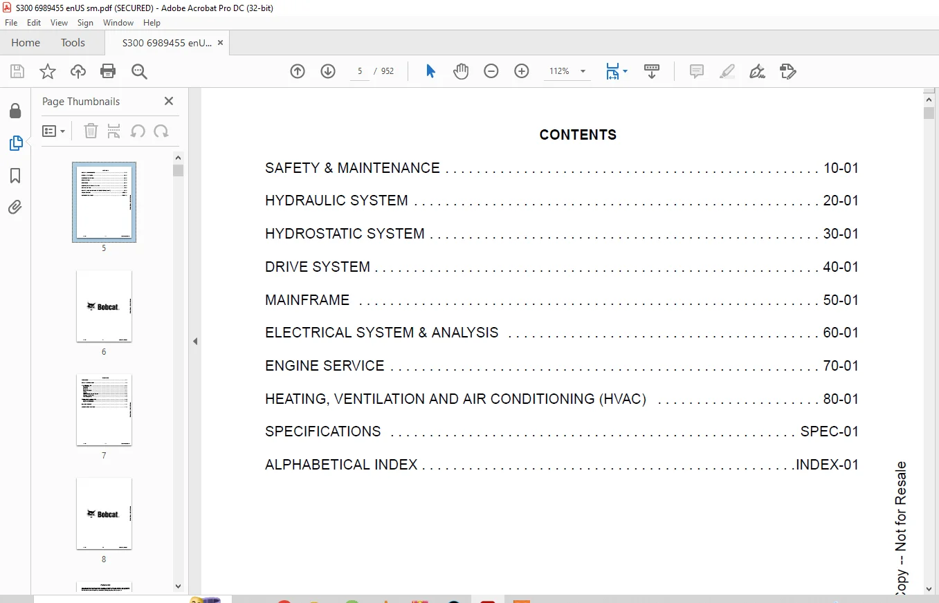
TABLE OF CONTENTS:
Bobcat S300 Skid-Steer Loader Service Manual SN AJ4M11001 & Above – PDF DOWNLOAD
MAINTENANCE SAFETY 3
CONTENTS 5
FOREWORD 7
FOREWORD 9
SAFETY INSTRUCTIONS 11
FIRE PREVENTION 13
Maintenance 13
Operation 13
Electrical 13
Hydraulic System 13
Fueling 13
Starting 13
Spark Arrester Exhaust System 13
Welding And Grinding 14
Fire Extinguishers 14
SERIAL NUMBER LOCATION 15
Loader Serial Number 15
Engine Serial Number 15
DELIVERY REPORT 16
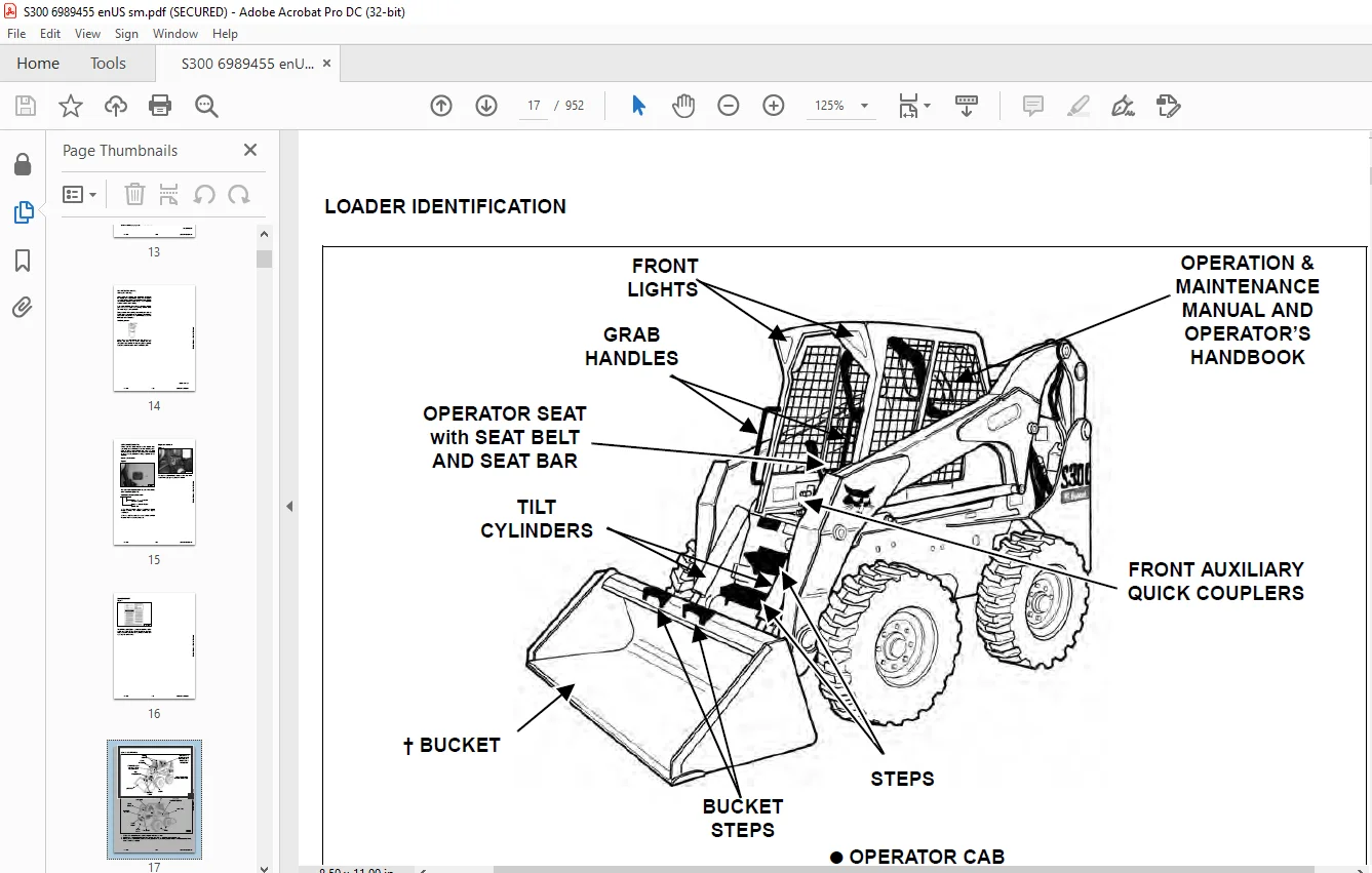
LOADER IDENTIFICATION 17
SAFETY & MAINTENANCE 19
LIFTING AND BLOCKING THE LOADER 23
Procedure 23
LIFT ARM SUPPORT DEVICE 25
Installing 25
Removing 26
OPERATOR CAB 27
Description 27
Raising 28
Lowering 29
Cab Door Sensor 30
Special Applications Kit 30
Special Applications Kit Inspection And Maintenance 30
Forestry Door And Window Kit 31
Forestry Door And Window Kit Inspection And Maintenance 31
TRANSPORTING THE LOADER ON A TRAILER 33
Loading And Unloading 33
Fastening 33
TOWING THE LOADER 35
Procedure 35
REMOTE START TOOL KIT- MEL1563 37
Remote Start Tool – MEL1563 37
SERVICE TOOL HARNESS COMMUNICATOR – MEL1566 39
Remote Start Procedure 40
REMOTE START TOOL (SERVICE TOOL) KIT – 7217666 43
Description 43
Remote Start Tool (Service Tool) – 7022042 44
Loader Service Tool Harness – 6689747 45
Computer Service Tool Harness – 6689746 46
Remote Start Procedure 47
SERVICE SCHEDULE 51
Chart 51
AIR CLEANER SERVICE 53
Replacing Filter Elements 53
ENGINE COOLING SYSTEM 55
Maintenance Platform 55
Cleaning 55
Removing And Replacing Coolant 57
Checking Level 57
FUEL SYSTEM 59
Fuel Specifications 59
Biodiesel Blend Fuel 59
Filling The Fuel Tank 60
Fuel Filter 61
Removing Air From The Fuel System 61
ENGINE LUBRICATION SYSTEM 63
Checking And Adding Engine Oil 63
Engine Oil Chart 63
Removing And Replacing Oil And Filter 64
HYDRAULIC / HYDROSTATIC SYSTEM 65
Checking And Adding Fluid 65
Hydraulic / Hydrostatic Fluid Chart 65
Removing And Replacing Hydraulic Fluid 66
Removing And Replacing Hydraulic / Hydrostatic Filter 67
Removing And Replacing Case Drain Filters 68
Removing And Replacing Hydraulic Charge Filter 69
Breather Cap 70
FINAL DRIVE TRANSMISSION (CHAINCASE) 71
Checking And Adding Oil 71
Removing And Replacing Oil 71
BOB-TACH (HAND LEVER) 73
Inspection And Maintenance 73
BOB-TACH (POWER) 75
Inspection And Maintenance 75
LUBRICATING THE LOADER 77
Lubrication Locations 77
TIRE MAINTENANCE 79
Wheel Nuts 79
Rotating 79
Mounting 80
SPARK ARRESTER MUFFLER 81
Cleaning Procedure 81
PIVOT PINS 83
Inspection And Maintenance 83
LOADER STORAGE AND RETURN TO SERVICE 85
Storage 85
Return To Service 85
STOPPING THE ENGINE AND LEAVING THE LOADER 87
Procedure 87
EMERGENCY EXIT 89
Rear Window 89
Front Door 89
SEAT BELT 91
Inspection And Maintenance 91
HYDRAULIC SYSTEM 93
HYDRAULIC/HYDROSTATIC SCHEMATIC 97
HYDRAULIC SYSTEM INFORMATION 113
Glossary Of Hydraulic / Hydrostatic Symbols 113
Troubleshooting 117
CYLINDER (LIFT) 119
Testing 119
Removal And Installation 120
Parts Identification 122
Disassembly 123
Assembly 125
CYLINDER (TILT) 129
Testing 129
Removal And Installation 130
Base End Pivot Pin Removal And Installation 132
Parts Identification 133
Disassembly 134
Assembly 136
CYLINDER (BOB-TACH) 139
Testing 139
Removal And Installation 140
Parts Identification 141
Disassembly 142
Assembly 143
MAIN RELIEF VALVE 147
Description 147
Testing 148
Adjusting 150
Removal And Installation 151
HYDRAULIC CONTROL VALVE (STANDARD) 153
Description 153
Removal And Installation 154
Identification Chart 158
Mount Bracket Removal And Installation 159
Lift Load Check Valve Removal And Installation 159
Load Check Valve Removal And Installation (Tilt And Auxiliary) 160
Anti-Cavitation Valve Removal And Installation (Lift, Rod End) 160
Port Relief / Anti-Cavitation Valve Removal And Installation (Lift, Base End) 161
Port Relief / Anti-Cavitation Valve Removal And Installation (Tilt, Base End) 162
Port Relief / Anti-Cavitation Valve Removal And Installation (Tilt, Rod End) 162
Port Relief Valve Removal And Installation 163
Plug Removal And Installation 164
Rubber Boot Removal And Installation 165
End Cap Block Removal And Installation 166
Lift Spool And Detent Removal And Installation 167
Tilt Spool Removal And Installation 177
Auxiliary Spool Removal And Installation 179
Auxiliary Solenoid Removal And Installation 181
Solenoid Removal And Installation 182
Lock Valve Removal And Installation 183
Lift Arm Bypass Orifice Removal And Installation 185
Main Relief Valve Removal And Installation 185
Check Valve Removal And Installation 186
HYDRAULIC CONTROL VALVE (ACS) OR (SJC) 187
Description 187
Removal And Installation 188
Actuator Removal And Installation (In Loader) 192
Actuator Removal And Installation (Out Of Loader) 194
Identification Chart 197
Mount Bracket Removal And Installation 198
Lift Load Check Valve Removal And Installation 198
Load Check Valve Removal And Installation (Tilt And Auxiliary) 199
Anti-Cavitation Valve Removal And Installation (Lift, Rod End) 200
Port Relief / Anti-Cavitation Valve Removal And Installation (Lift, Base End) 201
Port Relief / Anti-Cavitation Valve Removal And Installation (Tilt, Base End) 201
Port Relief / Anti-Cavitation Valve Removal And Installation (Tilt, Rod End) 202
Port Relief Valve Removal And Installation 202
Plug Removal And Installation 203
End Cap Block Removal And Installation 204
Lift Spool And Detent Removal And Installation 205
Tilt Spool Removal And Installation 210
Auxiliary Spool Removal And Installation 212
Auxiliary Solenoid Removal And Installation 214
Solenoid Removal And Installation 215
Lock Valve Removal And Installation 216
Lift Arm Bypass Orifice Removal And Installation 218
Main Relief Valve Removal And Installation 218
Check Valve Removal And Installation 219
LIFT ARM BYPASS CONTROL VALVE 221
Description 221
Testing 221
Removal And Installation 222
Disassembly And Assembly 223
HYDRAULIC PUMP (STANDARD) 225
Description 225
Pump Test at Quick Couplers 226
Direct Pump Test (Standard Section) 227
Direct Pump Test (Charge Section) 229
Removal And Installation 233
Hydraulic Pump Startup 235
Parts Identification 236
Disassembly And Assembly 237
HYDRAULIC PUMP (STANDARD) (HIGH FLOW) 239
Description 239
Pump Test At Quick Couplers 240
Direct Pump Test (Standard Section) 241
Direct Pump Test (Charge Section) 243
Direct Pump Test (High Flow Section) 247
High Flow Relief Valve Adjustment 249
High Flow Relief Valve Removal And Installation 251
Solenoid Removal And Installation 252
Removal And Installation 253
Hydraulic Pump Startup 255
Parts Identification 256
Disassembly And Assembly 257
HYDRAULIC PUMP (SJC) 259
Description 259
Pump Test At Quick Couplers 260
Direct Pump Test (Standard Section) 261
Direct Pump Test (Charge Section) 263
Removal And Installation 267
Hydraulic Pump Startup 269
Parts Identification 270
Disassembly And Assembly 271
HYDRAULIC PUMP (SJC) (HIGH FLOW) 273
Description 273
Pump Test At Quick Couplers 274
Direct Pump Test (Standard Section) 275
Direct Pump Test (Charge Section) 277
Direct Pump Test (High Flow Section) 281
High Flow Relief Valve Adjustment 283
High Flow Relief Valve Removal And Installation 285
Solenoid Removal And Installation 286
Removal And Installation 287
Hydraulic Pump Startup 289
Parts Identification 290
Disassembly And Assembly 291
HYDRAULIC / HYDROSTATIC FILTERS 293
Description 293
Housing Removal And Installation 293
HYDRAULIC FLUID RESERVOIR 295
Description 295
Removal And Installation 295
Hydraulic Fluid Screen 298
OIL COOLER 299
Description 299
Removal And Installation 299
BUCKET POSITION VALVE 303
Description 303
Solenoid Removal And Installation 304
Solenoid Testing 305
Removal And Installation 305
Disassembly And Assembly 306
REAR AUXILIARY DIVERTER VALVE 309
Description 309
Solenoid Testing 309
Removal And Installation 310
Disassembly And Assembly 312
BOB-TACH (POWER) BLOCK 319
Description 319
Removal And Installation 319
Disassembly And Assembly 321
FRONT AUXILIARY HYDRAULIC COUPLER BLOCK 325
Description 325
Removal And Installation 325
Disassembly And Assembly 326
HYDROSTATIC SYSTEM 329
HYDROSTATIC SYSTEM INFORMATION 331
Troubleshooting 331
Description 332
HYDROSTATIC MOTOR 333
Description 333
Removal And Installation 334
Parts Identification 336
Disassembly And Assembly 337
HYDROSTATIC MOTOR (TWO-SPEED) 341
Description 341
Removal And Installation 342
Parts Identification 345
Disassembly 346
Assembly 352
HYDROSTATIC MOTOR CARRIER 357
Description 357
Removal And Installation 358
Parts Identification 359
Disassembly 360
Assembly 361
HYDROSTATIC MOTOR CARRIER (SJC) 363
Description 363
Removal And Installation 364
Parts Identification 365
Disassembly 366
Assembly 368
CHARGE PRESSURE 371
Description 371
Testing 372
Sender Removal And Installation 374
Adjusting 375
HYDROSTATIC PUMP 377
Description 377
Removal And Installation 378
Hydrostatic Pump Startup 380
Replenishing / High Pressure Relief Valve Removal And Installation 380
Parts Identification (Left Half) 381
Parts Identification (Right Half) 382
Disassembly 383
Assembly 390
HYDROSTATIC PUMP (SJC) 397
Description 397
Hydraulic Controller Removal And Installation 398
Removal And Installation 400
Hydrostatic Pump Startup 401
Parts Identification 402
High Pressure Relief And Bypass Valve 403
Charge Relief Valve 404
Disassembly And Assembly 405
Mechanical Neutral Adjustment 418
Hydraulic Controller Neutral Adjustment 421
DRIVE BELT 425
Description 425
Shield Removal And Installation 425
Adjusting 426
Belt Removal And Installation 426
Tensioner Pulley Removal And Installation 427
Tensioner Pulley Disassembly And Assembly 428
Tensioner Pulley Tension Spring Removal And Installation 429
Tensioner Pulley Tension Disassembly And Assembly 429
CASE DRAIN FILTER 431
Description 431
Disassembly And Assembly 431
DRIVE SYSTEM 433
BRAKE 435
Description 435
Disc Removal And Installation 436
BRAKE (TWO-SPEED) 439
Description 439
Block Removal And Installation 440
Block Disassembly And Assembly 442
DRIVE COMPONENTS 447
Description 447
Axle Seal Removal And Installation 448
Axle, Sprocket And Bearings Removal And Installation 450
Chain Removal And Installation 454
CHAINCASE 457
Description 457
Front Cover Removal And Installation 457
Center Cover Removal And Installation 458
Rear Cover Removal And Installation 459
MAINFRAME 461
SEAT BAR 465
Description 465
Removal And Installation 465
Disassembly And Assembly 466
Compression Spring Disassembly And Assembly 467
OPERATOR CAB 469
Gas Cylinder Removal And Installation 469
Gas Cylinder Bracket Disassembly And Assembly 471
Removal And Installation 472
OPERATOR SEAT 475
Removal And Installation 475
Seat Belt Removal And Installation 475
OPERATOR SEAT (SUSPENSION) 477
Removal And Installation 477
Slide Rail Removal And Installation 478
Seat Belt Removal And Installation 478
Lower Cushion Removal And Installation 479
Back Cushion Removal And Installation 480
Shock Removal And Installation 480
3-Point Seat Belt Removal And Installation 481
BOB-TACH (HAND LEVER) 483
Description 483
Removal And Installation 483
Lever And Wedge Disassembly And Assembly 486
Pivot Pin Bushing And Seal Removal And Installation 487
BOB-TACH (POWER) 489
Description 489
Removal And Installation 489
Lever And Wedge Disassembly And Assembly 492
Pivot Pin Bushing And Seal Removal And Installation 494
LIFT ARMS 495
Stabilizer Bar Removal And Installation 495
Link Removal And Installation 496
Removal And Installation 497
REAR GRILLE 501
Removal And Installation 501
REAR DOOR 503
Removal And Installation 503
Striker Removal And Installation 504
Striker Disassembly And Assembly 504
Striker (Adjusting) 505
Latch Removal And Installation 506
FUEL TANK 507
Removal And Installation 507
Fuel Level Sender Removal And Installation 510
Fuel Fill Screen Removal And Installation 510
CONTROL PEDALS AND LINKAGES 511
Description 511
Pedal Removal And Installation 512
Linkage Removal And Installation 513
Pedal (Adjusting) 514
CONTROL PEDALS (ACS) 515
Description 515
Foot Sensor Removal And Installation 516
Foot Pedal Removal And Installation 517
Foot Pedal Linkage Disassembly And Assembly 517
CONTROL PANEL 519
Description 519
Removal And Installation 520
Shock Removal And Installation 522
Shaft Removal And Installation 523
Shaft Disassembly And Assembly 523
Linkage Removal And Installation 524
Pintle Arm Disassembly And Assembly 528
Linkage Neutral (Adjusting) 529
Linkage Travel (Adjusting) 533
CONTROL PANEL (SJC) 537
Description 537
Removal And Installation 538
CONTROL HANDLE / LEVER 541
Description 541
Lever Removal And Installation 541
Boot Removal And Installation 542
CONTROL HANDLE / LEVER (ACS) 543
Description 543
Handle Sensor Removal And Installation 543
Handle Removal And Installation 546
Handle Disassembly And Assembly 547
Lever Removal And Installation 548
Boot Removal And Installation 549
CONTROL HANDLE / LEVER (SJC) 551
Description 551
Joystick Testing 552
Joystick Removal And Installation 553
Joystick Mount Removal And Installation 554
ACCESS PANEL (INSIDE) 555
Removal And Installation (Left) 555
Removal And Installation (Right) 555
ACCESS PANEL (INSIDE) (SJC) 557
Removal And Installation (Left) 557
Removal And Installation (Right) 558
WINDOW (REAR) 561
Removal 561
Installation 561
WINDOW (TOP) 563
Removal And Installation 563
WINDOW (SIDE) 565
Removal And Installation 565
WINDOW (CAB DOOR) 567
Removal (Standard Window) 567
Installation (Standard Window) 568
Removal And Installation (Special Applications Window) 570
CAB DOOR 571
Description 571
Removal And Installation 571
Aligning 572
Adjusting 573
Checking Operation 573
ELECTRICAL SYSTEM & ANALYSIS 575
ELECTRICAL SCHEMATICS 579
ELECTRICAL SYSTEM INFORMATION 585
Glossary Of Electrical Symbols 585
Cab Harness Connectors 588
Mainframe Harness Connectors 589
Description 591
Troubleshooting 592
Fuse And Relay Location / Identification 593
Solenoid Testing 594
BATTERY 595
Removal And Installation 595
Servicing 596
Using A Booster Battery (Jump Starting) 597
ALTERNATOR 599
Belt Adjustment 599
Belt Replacement 599
Charging System Inspection 600
Alternator Voltage Testing 601
Low Voltage Testing 601
High Voltage Testing 602
Removal And Installation 603
Parts Identification 604
STARTER 605
Testing 605
Removal And Installation 606
Parts Identification 607
INSTRUMENT PANELS 609
Left Panel 609
Standard Key Panel 611
Keyless Start Panel 611
Deluxe Instrumentation Panel 612
Side Panel 613
Front Panel 613
Front Panel Removal And Installation 614
Removal And Installation (Left And Right) 614
Key Switch Removal And Installation 616
Alarm Removal And Installation 617
LIGHTS 619
Front Removal And Installation 619
Rear Removal And Installation 620
Cab Light Removal And Installation 620
BOBCAT CONTROLLER (GATEWAY AND AUXILIARY) 621
Description 621
Connector Identification 622
Removal And Installation 628
BOBCAT CONTROLLER (ACS) 629
Description 629
Connector And Wire Identification 630
Removal And Installation 631
BOBCAT CONTROLLER (SJC) (DRIVE) 633
Description 633
Connector Identification 634
Removal And Installation 636
SPEED SENSOR (SJC) 637
Description 637
Testing 638
Removal And Installation 639
DIAGNOSTIC SERVICE CODES 641
Viewing Service Codes 641
Service Codes List 642
BOBCAT INTERLOCK CONTROL SYSTEM (BICS™) 647
Description 647
Inspecting The BICS™ (Engine STOPPED – Key ON) 647
Inspecting Deactivation Of The Auxiliary Hydraulics System (Engine STOPPED – Key ON) 647
Inspecting The Seat Bar Sensor (Engine RUNNING) 647
Inspecting The Traction Lock (Engine RUNNING) 647
Inspecting The Lift Arm Bypass Control 647
Inspecting Deactivation Of Lift And Tilt Functions (ACS and SJC) 648
Troubleshooting 648
SEAT BAR SENSOR 649
Description 649
Troubleshooting 649
Testing 650
Removal And Installation 651
Bobcat Interlock Control System (BICS™) Circuit Test 654
TRACTION LOCK 657
Description 657
Troubleshooting 658
Removal And Installation (Single Speed) 659
Inspecting (Single And Two-Speed) 663
CONTROL SYSTEM (ACS) 665
Description 665
Troubleshooting 666
Handle Sensor Connector Disassembly And Assembly 667
Switch Handle Removal 668
Switch Handle Installation 670
Actuator Connector Disassembly And Assembly 673
Handle Lock Solenoid Removal And Installation 674
Handle Lock Solenoid Disassembly And Assembly 675
Foot Sensor Disassembly And Assembly 675
Foot Lock Solenoid Removal And Installation 676
ELECTRICAL / HYDRAULIC CONTROLS 677
Identification Chart 677
Description 678
Identification Chart ACD Group 0 679
Identification Chart ACD Group 1 680
Identification Chart ACD Group 2 681
Identification Chart ACD Group 3 682
ELECTRICAL / HYDRAULIC CONTROLS (SJC) 683
Identification Chart 683
Description 684
Identification Chart ACD Group 0 685
Identification Chart ACD Group 1 686
Identification Chart ACD Group 2 687
Identification Chart ACD Group 3 688
SERVICE PC (LAPTOP COMPUTER) 689
Connecting Remote Start Tool 689
Connecting Remote Start Tool (Service Tool) 689
CALIBRATION 691
Description 691
Actuator Testing 691
Lift And Tilt Calibration (SJC) 694
Hydrostatic Pump Calibration (SJC) 696
Lift And Tilt Calibration (ACS) 701
STEERING DRIFT COMPENSATION 703
Description 703
Operation 703
FLYWHEEL RPM SENSOR 705
Description 705
Adjusting 706
CONTROL PANEL SETUP 707
Right Panel Setup (Deluxe Instrumentation Panel) 707
Attachment Control Information (Deluxe Instrumentation Panel) 708
PASSWORD SETUP (DELUXE INSTRUMENTATION PANEL) 709
Password Description 709
Changing The Owner Password 709
Changing The User Passwords 710
Password Lockout Feature 710
PASSWORD SETUP (KEYLESS START PANEL) 711
Password Description 711
Changing The Owner Password 711
Password Lockout Feature 711
MAINTENANCE CLOCK 713
Description 713
Setup 714
Reset 717
BACK-UP ALARM SYSTEM 719
Description 719
Inspecting 719
Adjusting Switch Position 720
Troubleshooting (Standard And ACS) 721
Troubleshooting (Joystick) 722
Alarm Removal And Installation 723
Switch Removal And Installation 723
ENGINE SERVICE 725
ENGINE INFORMATION 729
Description 729
Specifications 730
Torque Values 734
Troubleshooting 735
Engine Removal And Installation 737
Engine Mount Replacement 744
Compression – Testing 745
ENGINE SPEED CONTROL 747
Removal And Installation 747
Cable Removal And Installation 747
ENGINE SPEED CONTROL (SJC) 749
Removal And Installation 749
Disassembly And Assembly 751
Cable Removal And Installation 752
MUFFLER 753
Removal And Installation 753
AIR CLEANER 755
Housing Removal And Installation 755
ENGINE COOLING SYSTEM 757
Radiator Removal And Installation 757
Radiator Mount Removal And Installation 759
Hydraulic Fan Motor Description 760
Axial Fan Housing Removal And Installation 761
Axial Fan Removal And Installation 763
Hydraulic Fan Motor Removal And Installation 765
Hydraulic Fan Motor Disassembly And Assembly 765
Water Pump Removal And Installation 767
Water Pump Disassembly And Assembly 767
Thermostat Housing Removal And Installation 768
Thermostat Testing 768
LUBRICATION SYSTEM 769
Oil Pan Removal And Installation 769
Oil Pump Removal And Installation 770
Oil Pump Inspection 770
Oil Filter Cooler Removal And Installation 772
Engine Oil Pressure – Testing 773
FUEL SYSTEM 775
Fuel Shutoff Solenoid – Testing 775
Fuel Shutoff Solenoid – Removal And Installation 775
Fuel Injection Pump Assembly Removal 776
Fuel Injection Pump Assembly Installation 780
Governor Housing Disassembly And Assembly 783
Governor Disassembly And Assembly 784
Fuel Camshaft Removal And Installation 787
Fuel Injection Pump Removal And Installation 789
Fuel Injection Pump Timing 797
Fuel Injector Removal And Installation 800
Fuel Injector Nozzle Pressure – Testing 801
Nozzle Spraying Condition 802
Valve Seat Tightness 802
CYLINDER HEAD 803
Intake Air Heater – Testing 803
Intake Air Heater Removal And Installation 803
Valve Clearance Adjustment 804
Valve Timing – Checking 805
Cylinder Head Removal And Installation 806
Cylinder Head Disassembly And Assembly 809
Cylinder Head – Servicing 809
Cylinder Head Top Clearance 810
Valve Guide – Checking 811
Valve Guide Removal And Installation 812
Reconditioning The Valve And Valve Seat 813
Valve Spring 815
Valve Tappets 816
Rocker Arm And Shaft – Checking 817
Push Rod Alignment – Checking 817
CRANKSHAFT AND PISTONS 819
Piston And Connecting Rod Removal And Installation 819
Piston And Connecting Rod – Servicing 821
Cylinder Bore Checking 826
Connecting Rod Alignment 827
Crankshaft Gear Removal And Installation 827
Crankshaft And Bearings Removal and Installation 828
Crankshaft And Bearings – Servicing 832
CAMSHAFT AND TIMING GEARS 839
Timing Gearcase Cover Removal And Installation 839
Timing Gears Backlash – Checking 840
Idle Gear And Camshaft Removal And Installation 841
Camshaft – Servicing 842
Idler Gear And Shaft – Servicing 844
TURBOCHARGER 847
Description 847
Testing 847
Removal And Installation 848
FLYWHEEL AND HOUSING 849
Flywheel Removal And Installation 849
Ring Gear Removal And Installation 850
Housing Removal And Installation 850
HEATING, VENTILATION AND AIR CONDITIONING (HVAC) 851
AIR CONDITIONING SYSTEM FLOW 854
Description 854
Chart 855
Components 856
Safety Equipment 859
REGULAR MAINTENANCE 861
Filters 861
Compressor Drive Belt Adjustment 862
Compressor Drive Belt Replacement 862
Condenser 863
Air Conditioning Lubrication 863
Air Conditioning Service Chart 863
Evaporator / Heater Coil 864
TROUBLESHOOTING 865
Blower Motor Does Not Operate 865
Blower Motor Operates Normally, But Air Flow Is Insufficient 865
Insufficient Cooling Although Air Flow And Compressor Operation Are Normal 865
The Compressor Does Not Operate At All, Or Operates Improperly 865
Gauge Pressure Related Troubleshooting 866
Troubleshooting Tree 868
Temperature / Pressure Chart 872
Poor A/C Performance 874
HVAC Repair And Leaks 875
Electrical System 876
Engine Coolant Bypassing The Heater Valve 883
Heater Valve Not Opening Or Closing 884
SYSTEM CHARGING AND RECLAMATION 885
Refrigerant Identification 885
Reclamation And Charging With Recovery / Charging Unit 886
Charging With A Manifold Gauge Set 888
COMPRESSOR 891
Removal And Installation 891
Oil 892
Oil Check 892
Clutch Disassembly And Assembly 894
CONDENSER 899
Removal And Installation 899
RECEIVER / DRIER 901
Receiver / Drier Removal And Installation 901
Pressure Relief Valve Removal And Installation 902
Pressure Switch Removal And Installation 902
Schraeder® Valve Removal And Installation 903
EVAPORATOR / HEATER UNIT 905
Removal And Installation 905
THERMOSTAT 907
Description 907
Removal And Installation 908
EXPANSION VALVE 909
Removal And Installation 909
EVAPORATOR COIL 911
Removal And Installation 911
HEATER COIL 913
Removal And Installation With A/C 913
Removal And Installation Without A/C 915
BLOWER FAN 917
Removal And Installation 917
Disassembly And Assembly 918
Connector Identification 920
HEATER VALVE 921
Removal And Installation 921
Disassembly And Assembly 922
SPECIFICATIONS 923
(S300) LOADER SPECIFICATIONS 925
Machine Dimensions 925
Performance 926
Engine 926
Drive System 926
Controls 927
Hydraulic System 927
Electrical 928
Capacities 928
Tires 928
TORQUE SPECIFICATIONS FOR BOLTS 929
Torque For General SAE Bolts 929
Torque For General Metric Bolts 930
HYDRAULIC CONNECTION SPECIFICATIONS 931
O-ring Face Seal Connection 931
Straight Thread O-ring Fitting 932
Tubelines And Hoses 932
Flare Fitting 933
Port Seal Fitting 934
HYDRAULIC / HYDROSTATIC FLUID SPECIFICATIONS 935
Specifications 935
CONVERSIONS 937
Decimal And Millimeter Equivalents 937
U S To Metric Conversion Chart 937
SERVICE TOOLS REQUIRED 939
Remote Start Tools 939
Hydraulic Tools 940
Mainframe And Drive Tools 942
Electrical Tools 943
Engine Tools 943
HVAC Tools 948
ALPHABETICAL INDEX 949
IMAGES PREVIEW OF THE MANUAL:
Questions? Email us: [email protected]
https://vimeo.com/843766782?share=copy
PLEASE NOTE:
- This is the same manual used by the dealers to diagnose and troubleshoot your vehicle
- You will be directed to the download page as soon as the purchase is completed. The whole payment and downloading process will take anywhere between 2-5 minutes
- Need any other service / repair / parts manual, please feel free to contact [email protected] . We still have 50,000 manuals unlisted
S.V


