Bobcat S330 Skid-Steer Loader Service Manual 6987040 – PDF DOWNLOAD
$34.95
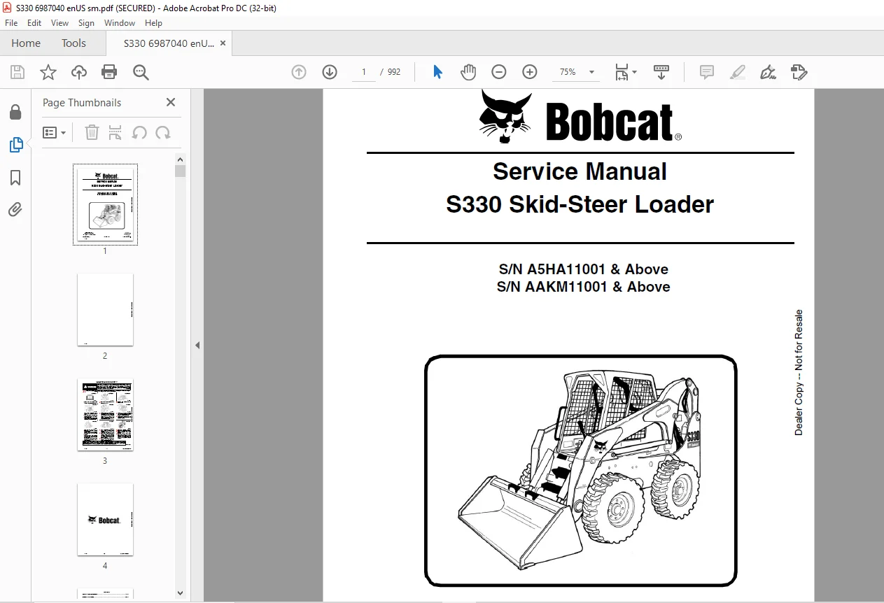
Bobcat S330 Skid-Steer Loader Service Manual 6987040 – PDF DOWNLOAD
S/N A5HA11001 & Above
S/N AAKM11001 & Above
Description
Bobcat S330 Skid-Steer Loader Service Manual 6987040 – PDF DOWNLOAD
FILE DETAILS:
Bobcat S330 Skid-Steer Loader Service Manual 6987040 – PDF DOWNLOAD
Language : English
Pages : 992
Downloadable : Yes
File Type : PDF
DESCRIPTION:
Bobcat S330 Skid-Steer Loader Service Manual 6987040 – PDF DOWNLOAD
S/N A5HA11001 & Above
S/N AAKM11001 & Above
FOREWORD:
This manual is for the Bobcat loader mechanic. It provides necessary servicing and adjustment procedures for the Bobcat loader and its component parts and systems. Refer to the Operation & Maintenance Manual for operating instructions, starting procedure, daily checks, etc.
A general inspection of the following items must be made after the loader has had service or repair:
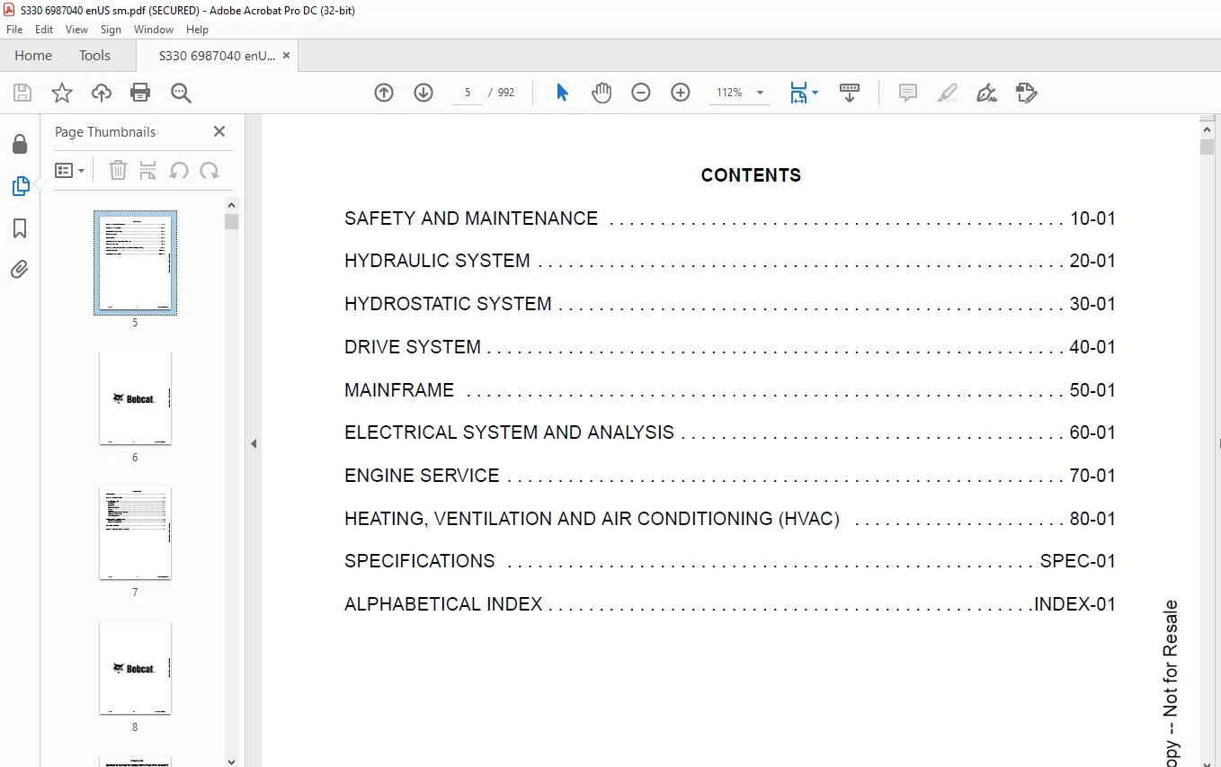
TABLE OF CONTENTS:
Bobcat S330 Skid-Steer Loader Service Manual 6987040 – PDF DOWNLOAD
MAINTENANCE SAFETY 3
CONTENTS 5
FOREWORD 7
FOREWORD 9
SAFETY INSTRUCTIONS 11
FIRE PREVENTION 13
Maintenance 13
Operation 13
Electrical 13
Hydraulic System 13
Fueling 13
Starting 13
Spark Arrester Exhaust System 13
Welding And Grinding 14
Fire Extinguishers 14
SERIAL NUMBER LOCATION 15
Loader Serial Number 15
Engine Serial Number 15
DELIVERY REPORT 16
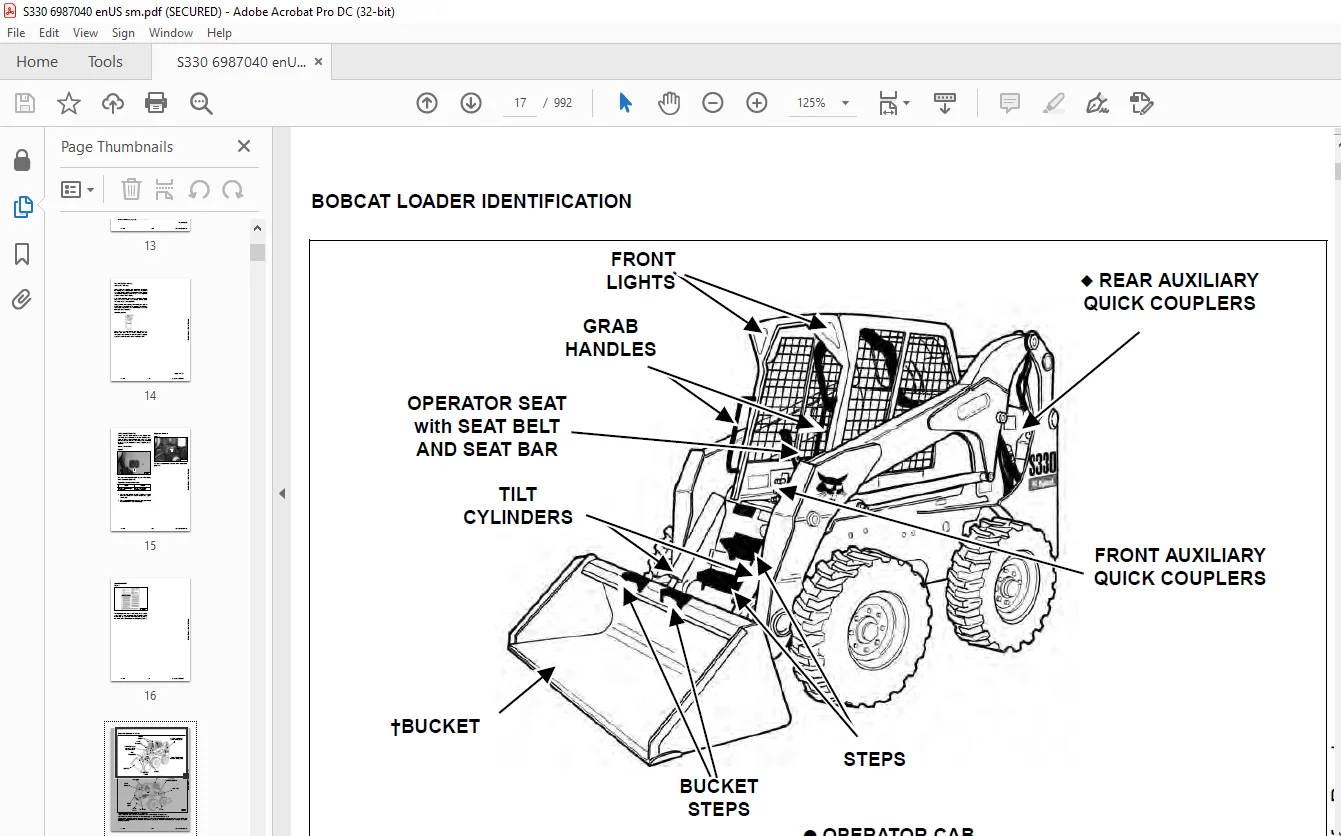
BOBCAT LOADER IDENTIFICATION 17
SAFETY AND MAINTENANCE 19
LIFTING AND BLOCKING THE LOADER 23
Procedure 23
LIFT ARM SUPPORT DEVICE 25
Installing 25
Removing 26
OPERATOR CAB 27
Description 27
Raising 27
Lowering 28
Cab Door Sensor 29
Special Applications Kit 30
Special Applications Kit Inspection And Maintenance 30
Forestry Door And Window Kit 31
Forestry Door And Window Kit Inspection And Maintenance 31
Forestry Door Emergency Exit 31
TRANSPORTING THE LOADER ON A TRAILER 33
Loading And Unloading 33
Fastening 33
TOWING THE LOADER 35
Procedure 35
REMOTE START TOOL KIT-MEL1563 37
Remote Start Tool – MEL1563 37
Service Tool Harness Communicator – MEL1566 39
Remote Start Procedure 40
REMOTE START TOOL (SERVICE TOOL) KIT – 7217666 43
Description 43
Remote Start Tool (Service Tool) – 7022042 44
Loader Service Tool Harness – 6689747 45
Computer Service Tool Harness – 6689746 46
Remote Start Procedure 47
SERVICE SCHEDULE 51
Chart 51
AIR CLEANER SERVICE 53
Replacing Filter Elements 53
ENGINE COOLING SYSTEM 55
Maintenance Platform 55
Description 55
Cleaning (Earlier Models) 55
Cleaning (Later Models) 57
Removing And Replacing Coolant 58
Checking Level 59
FUEL SYSTEM 61
Fuel Specifications 61
Biodiesel Blend Fuel 61
Filling The Fuel Tank 62
Fuel Filter 62
Removing Air From The Fuel System 63
ENGINE LUBRICATION SYSTEM 65
Checking And Adding Engine Oil 65
Engine Oil Chart 65
Removing And Replacing Oil And Filter 66
HYDRAULIC / HYDROSTATIC SYSTEM 67
Checking And Adding Fluid 67
Hydraulic / Hydrostatic Fluid Chart 67
Removing And Replacing Hydraulic Fluid 68
Removing And Replacing Hydraulic / Hydrostatic Filter 69
Removing And Replacing Case Drain Filters 70
Removing And Replacing Hydraulic Charge Filter 71
Breather Cap 72
FINAL DRIVE TRANSMISSION (CHAINCASE) 73
Checking And Adding Oil 73
Removing And Replacing Oil 73
BOB-TACH (HAND LEVER) 75
Inspection And Maintenance 75
BOB-TACH (POWER) 77
Inspection And Maintenance 77
LUBRICATING THE LOADER 79
Lubrication Locations 79
TIRE MAINTENANCE 81
Wheel Nuts 81
Rotating 82
Mounting 82
SPARK ARRESTER MUFFLER 83
Cleaning Procedure 83
PIVOT PINS 85
Inspection And Maintenance 85
LOADER STORAGE AND RETURN TO SERVICE 87
Storage 87
Return To Service 87
STOPPING THE ENGINE AND LEAVING THE LOADER 89
Procedure 89
EMERGENCY EXIT 91
Rear Window 91
Front Door 91
SEAT BELT 93
Inspection And Maintenance 93
HYDRAULIC SYSTEM 95
HYDRAULIC/HYDROSTATIC SCHEMATICS 101
HYDRAULIC SYSTEM INFORMATION 117
Glossary Of Hydraulic / Hydrostatic Symbols 117
Troubleshooting 121
CYLINDER (LIFT) 123
Testing 123
Removal And Installation 124
Parts Identification 126
Disassembly 127
Assembly 129
CYLINDER (TILT) 133
Testing 133
Removal And Installation 134
Base End Pivot Pin Removal And Installation 136
Parts Identification 137
Disassembly 138
Assembly 140
CYLINDER (BOB-TACH) 143
Testing 143
Removal And Installation 144
Parts Identification 145
Disassembly 146
Assembly 147
MAIN RELIEF VALVE 151
Description 151
Testing 152
Adjusting 154
Removal And Installation 155
HYDRAULIC CONTROL VALVE (STANDARD) 157
Description 157
Removal And Installation 158
Identification Chart 162
Mount Bracket Removal And Installation 163
Lift Load Check Valve Removal And Installation 163
Load Check Valve Removal And Installation (Tilt And Auxiliary) 164
Anti-Cavitation Valve Removal And Installation (Lift, Rod End) 164
Port Relief / Anti-Cavitation Valve Removal And Installation (Lift, Base End) 165
Port Relief / Anti-Cavitation Valve Removal And Installation (Tilt, Base End) 166
Port Relief / Anti-Cavitation Valve Removal And Installation (Tilt, Rod End) 166
Port Relief Valve Removal And Installation 167
Plug Removal And Installation 168
Rubber Boot Removal And Installation 169
End Cap Block Removal And Installation 170
Lift Spool And Detent Removal And Installation 171
Tilt Spool Removal And Installation 181
Auxiliary Spool Removal And Installation 183
Auxiliary Solenoid Removal And Installation (S/N A5HA34999 & Below And AAKM34999 & Below) 185
Auxiliary Solenoid Removal And Installation (S/N A5HA35001 & Above And AAKM35001& Above) 186
Solenoid Removal And Installation 187
Lock Valve Removal And Installation 188
Lift Arm Bypass Orifice Removal And Installation 190
Main Relief Valve Removal And Installation 190
Check Valve Removal And Installation 191
HYDRAULIC CONTROL VALVE (ACS) OR (SJC) 193
Description 193
Removal And Installation 194
Actuator Removal And Installation (In Loader) 198
Actuator Removal And Installation (Out Of Loader) 200
Identification Chart 203
Mount Bracket Removal And Installation 204
Lift Load Check Valve Removal And Installation 204
Load Check Valve Removal And Installation (Tilt And Auxiliary) 205
Anti-Cavitation Valve Removal And Installation (Lift, Rod End) 206
Port Relief / Anti-Cavitation Valve Removal And Installation (Lift, Base End) 207
Port Relief / Anti-Cavitation Valve Removal And Installation (Tilt, Base End) 207
Port Relief / Anti-Cavitation Valve Removal And Installation (Tilt, Rod End) 208
Port Relief Valve Removal And Installation 208
Plug Removal And Installation 209
End Cap Block Removal And Installation 210
Lift Spool And Detent Removal And Installation 211
Tilt Spool Removal And Installation 216
Auxiliary Spool Removal And Installation 218
Auxiliary Solenoid Removal And Installation (S/N A5HA34999 & Below And AAKM34999 & Below) 220
Auxiliary Solenoid Removal And Installation (S/N A5HA35001 & Above And AAKM35001& Above) 221
Solenoid Removal And Installation 222
Lock Valve Removal And Installation 223
Lift Arm Bypass Orifice Removal And Installation 225
Main Relief Valve Removal And Installation 225
Check Valve Removal And Installation 226
LIFT ARM BYPASS CONTROL VALVE 227
Description 227
Testing 227
Removal And Installation 228
Disassembly And Assembly 229
HYDRAULIC PUMP (STANDARD) 231
Description 231
Pump Test At Quick Couplers 232
Direct Pump Test (Standard Section) 233
Direct Pump Test (Charge Section) 235
Removal And Installation 239
Hydraulic Pump Startup 241
Parts Identification 242
Disassembly And Assembly 243
HYDRAULIC PUMP (STANDARD) (HIGH FLOW) 245
Description 245
Pump Test At Quick Couplers 246
Direct Pump Test (Standard Section) 247
Direct Pump Test (Charge Section) 249
Direct Pump Test (High Flow Section) 253
High Flow Relief Valve Adjustment 255
High Flow Relief Valve Removal And Installation 258
Solenoid Removal And Installation 259
Removal And Installation 260
Hydraulic Pump Startup 262
Parts Identification 263
Disassembly And Assembly 264
HYDRAULIC PUMP (SJC) 265
Description 265
Pump Test At Quick Couplers 266
Direct Pump Test (Standard Section) 267
Direct Pump Test (Charge Section) 269
Removal And Installation 273
Hydraulic Pump Startup 275
Parts Identification 276
Disassembly And Assembly 277
HYDRAULIC PUMP (SJC) (HIGH FLOW) 279
Description 279
Pump Test At Quick Couplers 280
Direct Pump Test (Standard Section) 281
Direct Pump Test (Charge Section) 283
Direct Pump Test (High Flow Section) 287
High Flow Relief Valve Adjustment 289
High Flow Relief Valve Removal And Installation 292
Solenoid Removal And Installation 293
Removal And Installation 294
Hydraulic Pump Startup 296
Parts Identification 297
Disassembly And Assembly 298
HYDRAULIC / HYDROSTATIC FILTERS 299
Description 299
Housing Removal And Installation 299
HYDRAULIC FLUID RESERVOIR 301
Description 301
Removal And Installation 301
Hydraulic Fluid Screen 304
OIL COOLER 305
Description 305
Removal And Installation 305
BUCKET POSITION VALVE 309
Description 309
Solenoid Removal And Installation 310
Solenoid Testing 310
Removal And Installation 311
Disassembly And Assembly 311
REAR AUXILIARY DIVERTER VALVE 313
Description 313
Solenoid Testing 313
Removal And Installation 314
Disassembly And Assembly 316
BOB-TACH (POWER) BLOCK 323
Description 323
Removal And Installation 323
Disassembly And Assembly 325
FRONT AUXILIARY HYDRAULIC COUPLER BLOCK 329
Description 329
Removal And Installation 329
Disassembly And Assembly 330
HYDROSTATIC SYSTEM 333
HYDROSTATIC SYSTEM INFORMATION 335
Troubleshooting 335
Description 336
HYDROSTATIC DRIVE MOTOR 337
Description 337
Removal And Installation 338
Parts Identification 340
Disassembly And Assembly 341
HYDROSTATIC DRIVE MOTOR (TWO-SPEED) 345
Description 345
Removal And Installation 345
Parts Identification 348
Disassembly 349
Assembly 355
HYDROSTATIC MOTOR CARRIER 361
Description 361
Removal And Installation 362
Parts Identification 363
Disassembly 364
Assembly 365
HYDROSTATIC MOTOR CARRIER (SJC) 367
Description 367
Removal And Installation 368
Parts Identification 369
Disassembly 370
Assembly 372
CHARGE PRESSURE 375
Description 375
Testing 375
Sender Removal And Installation 377
Adjusting 378
HYDROSTATIC PUMP 381
Description 381
Removal And Installation 382
Hydrostatic Pump Startup 384
Replenishing / High Pressure Relief Valve Removal And Installation 385
Parts Identification (Left Half) 386
Parts Identification (Right Half) 387
Disassembly 388
Assembly 395
HYDROSTATIC PUMP (SJC) (S/N A5HA11001 – A5HA35031 AND AAKM11001 – AAKM35008) 401
Description 401
Hydraulic Controller Removal And Installation 402
Removal And Installation 404
Hydrostatic Pump Startup 406
Parts Identification 407
High Pressure Relief And Bypass Valve 408
Charge Relief Valve 409
Disassembly And Assembly 410
Mechanical Neutral Adjustment 427
Hydraulic Controller Neutral Adjustment 430
HYDROSTATIC PUMP (SJC) (S/N A5HA35032 & ABOVE AND AAKM35009 & ABOVE) 433
Description 433
Hydraulic Controller Removal And Installation 434
Removal And Installation 436
Hydrostatic Pump Startup 437
Parts Identification 438
High Pressure Relief And Bypass Valve 439
Charge Relief Valve 440
Disassembly And Assembly 441
Mechanical Neutral Adjustment 454
Hydraulic Controller Neutral Adjustment 457
DRIVE BELT 461
Description 461
Shield Removal And Installation 461
Adjusting 462
Belt Removal And Installation 462
Tensioner Pulley Removal And Installation 463
Tensioner Pulley Disassembly And Assembly 464
Tensioner Pulley Tension Spring Removal And Installation 465
Tensioner Pulley Tension Spring Disassembly And Assembly 465
CASE DRAIN FILTER 467
Description 467
Disassembly And Assembly 467
DRIVE SYSTEM 469
BRAKE 471
Description 471
Block Removal And Installation 472
Block Disassembly And Assembly 474
DRIVE COMPONENTS 479
Description 479
Axle Seal Removal And Installation 480
Axle, Sprocket And Bearings Removal And Installation 482
Chain Removal And Installation 487
CHAINCASE 489
Description 489
Front Cover Removal And Installation 489
Center Cover Removal And Installation 490
Rear Cover Removal And Installation 491
MAINFRAME 493
SEAT BAR 497
Description 497
Removal And Installation 497
Disassembly And Assembly 498
Compression Spring Disassembly And Assembly 499
OPERATOR CAB 501
Gas Cylinder Removal And Installation 501
Gas Cylinder Bracket Disassembly And Assembly 503
Removal And Installation 504
OPERATOR SEAT 507
Removal And Installation 507
Seat Belt Removal And Installation 507
OPERATOR SEAT (SUSPENSION) 509
Removal And Installation 509
Slide Rail Removal And Installation 510
Seat Belt Removal And Installation 510
Lower Cushion Removal And Installation 511
Back Removal And Installation 512
Shock Removal And Installation 512
3-Point Seat Belt Removal And Installation 513
BOB-TACH (HAND LEVER) 515
Description 515
Removal And Installation 515
Lever And Wedge Disassembly And Assembly 518
Pivot Pin Bushing And Seal Removal And Installation 519
BOB-TACH (POWER) 521
Description 521
Removal And Installation 521
Lever And Wedge Disassembly And Assembly 524
Pivot Pin Bushing And Seal Removal And Installation 526
LIFT ARMS 527
Stabilizer Bar Removal And Installation 527
Link Removal And Installation 528
Removal And Installation 529
REAR GRILLE 533
Removal And Installation 533
REAR DOOR (TAILGATE) 535
Removal And Installation 535
Striker Removal And Installation 536
Striker Disassembly And Assembly 536
Striker (Adjusting) 537
Latch Removal And Installation 538
FUEL TANK 539
Removal And Installation 539
Fuel Level Sender Removal And Installation 542
Fuel Fill Screen Removal And Installation 542
CONTROL PEDALS AND LINKAGES 543
Description 543
Pedal Removal And Installation 544
Linkage Removal And Installation 545
Pedal (Adjusting) 546
CONTROL PEDALS (ACS) 547
Description 547
Foot Sensor Removal And Installation 548
Foot Pedal Removal And Installation 549
Foot Pedal Linkage Disassembly And Assembly 549
CONTROL PANEL 551
Description 551
Removal And Installation 552
Shock Removal And Installation 554
Shaft Removal And Installation 555
Linkage Removal And Installation 556
Pintle Arm Disassembly And Assembly 560
Linkage Neutral (Adjusting) 561
Linkage Travel (Adjusting) 565
CONTROL PANEL (SJC) 569
Description 569
Removal And Installation 570
CONTROL HANDLE / LEVER 573
Description 573
Lever Removal And Installation 573
Boot Removal And Installation 574
CONTROL HANDLE / LEVER (ACS) 575
Description 575
Handle Sensor Removal And Installation 575
Handle Removal And Installation 578
Handle Disassembly And Assembly 579
Lever Removal And Installation 580
Boot Removal And Installation 581
CONTROL HANDLE / LEVER (SJC) 583
Description 583
Joystick Testing 584
Joystick Removal And Installation 585
Joystick Mount Removal And Installation 586
ACCESS PANEL (INSIDE) 587
Removal And Installation (Left) 587
Removal And Installation (Right) 587
ACCESS PANEL (INSIDE) (SJC) 589
Removal And Installation (Left) 589
Removal And Installation (Right) 590
WINDOW (REAR) 593
Removal 593
Installation (Split Molding) 593
Installation (Continuous Molding) 595
WINDOW (TOP) 597
Removal And Installation 597
WINDOW (SIDE) 599
Removal And Installation 599
WINDOW (CAB DOOR) 601
Removal (Standard Window) 601
Installation (Standard Window) 602
Removal And Installation (Special Applications Window) 604
CAB DOOR 605
Description 605
Removal And Installation 605
Aligning 606
Adjusting 607
Checking Operation 607
ELECTRICAL SYSTEM AND ANALYSIS 609
ELECTRICAL SCHEMATICS 613
ELECTRICAL SYSTEM INFORMATION 619
Glossary Of Electrical Symbols 619
Cab Harness Connectors 622
Mainframe Harness Connectors 623
Description 625
Troubleshooting 626
Fuse And Relay Location / Identification 627
Solenoid Testing 628
BATTERY 629
Removal And Installation 629
Servicing 630
Using A Booster Battery (Jump Starting) 631
ALTERNATOR 633
Belt Adjustment 633
Belt Replacement 633
Charging System Inspection 634
Alternator Voltage Testing 635
Low Voltage Testing 635
High Voltage Testing 636
Removal And Installation 637
Parts Identification 638
STARTER 639
Testing 639
Removal And Installation 640
Parts Identification 641
INSTRUMENT PANELS 643
Left Panel 643
Standard Key Panel 645
Keyless Start Panel 645
Deluxe Instrumentation Panel 646
Side Panel 647
Front Panel 647
Front Panel Removal And Installation 648
Removal And Installation (Left And Right) 648
Key Switch Removal And Installation 650
Alarm Removal And Installation 651
LIGHTS 653
Front Removal And Installation 653
Rear Removal And Installation 654
Cab Light Removal And Installation 654
BOBCAT CONTROLLER (GATEWAY AND AUXILIARY) 655
Description 655
Connector Identification 656
Removal And Installation 662
BOBCAT CONTROLLER (ACS) 663
Description 663
Connector And Wire Identification 664
Removal And Installation 665
BOBCAT CONTROLLER (SJC) (DRIVE) 667
Description 667
Connector Identification 668
Removal And Installation 670
SPEED SENSORS (SJC) 671
Description 671
Testing 672
Removal And Installation 674
DIAGNOSTIC SERVICE CODES 677
Viewing Service Codes (Standard Key Panel And Keyless Start Panel) 677
Viewing Service Codes (Deluxe Instrumentation Panel) 677
Service Codes List 678
BOBCAT INTERLOCK CONTROL SYSTEM (BICS™) 683
Description 683
Inspecting The BICS™ (Engine STOPPED – Key ON) 684
Inspecting Deactivation Of The Auxiliary Hydraulics System (Engine STOPPED – Key ON) 684
Inspecting The Seat Bar Sensor (Engine RUNNING) 684
Inspecting The Traction Lock (Engine RUNNING) 684
Inspecting The Lift Arm Bypass Control 684
Inspecting Deactivation Of Lift And Tilt Functions (ACS and SJC) 684
Troubleshooting 685
SEAT BAR SENSOR 687
Description 687
Troubleshooting 687
Testing 688
Removal And Installation 689
Bobcat Interlock Control System (BICS™) Circuit Test 692
TRACTION LOCK 695
Description 695
Troubleshooting 696
Inspecting 697
CONTROL SYSTEM (ACS) 699
Description 699
Troubleshooting 700
Handle Sensor Connector Disassembly And Assembly 701
Switch Handle Removal 702
Switch Handle Installation 704
Actuator Connector Disassembly And Assembly 707
Handle Lock Solenoid Removal And Installation 708
Handle Lock Solenoid Disassembly And Assembly 709
Foot Sensor Disassembly And Assembly 709
Foot Lock Solenoid Removal And Installation 710
ELECTRICAL / HYDRAULIC CONTROLS 711
Identification Chart 711
Description 712
Identification Chart ACD Group 0 713
Identification Chart ACD Group 1 714
Identification Chart ACD Group 2 715
Identification Chart ACD Group 3 716
ELECTRICAL / HYDRAULIC CONTROLS (ACS) 717
Identification Chart 717
Description 718
Identification Chart ACD Group 0 719
Identification Chart ACD Group 1 720
Identification Chart ACD Group 2 721
Identification Chart ACD Group 3 722
ELECTRICAL / HYDRAULIC CONTROLS (SJC) 723
Identification Chart 723
Description 724
Identification Chart ACD Group 0 725
Identification Chart ACD Group 1 726
Identification Chart ACD Group 2 727
Identification Chart ACD Group 3 728
SERVICE PC (LAPTOP COMPUTER) 729
Connecting Remote Start Tool 729
Connecting Remote Start Tool (Service Tool) 729
CALIBRATION 731
Description 731
Actuator Testing 731
Lift And Tilt Calibration (SJC) 734
Hydrostatic Pump Calibration (SJC) 736
Lift And Tilt Calibration (ACS) 741
STEERING DRIFT COMPENSATION 743
Description 743
Operation 743
FLYWHEEL RPM SENSOR 745
Description 745
Adjusting 746
CONTROL PANEL SETUP 747
Right Panel Setup (Deluxe Instrumentation Panel) 747
Attachment Control Information (Deluxe Instrumentation Panel) 748
PASSWORD SETUP (DELUXE INSTRUMENTATION PANEL) 749
Password Description 749
Changing The Owner Password 749
Changing The User Passwords 750
Password Lockout Feature 750
PASSWORD SETUP (KEYLESS START PANEL) 751
Password Description 751
Changing The Owner Password 751
Password Lockout Feature 751
MAINTENANCE CLOCK 753
Description 753
Setup 754
Reset 757
BACK-UP ALARM SYSTEM 759
Description 759
Inspecting 759
Adjusting Switch Position 760
Troubleshooting (Standard And ACS) 761
Troubleshooting (Joystick) 762
Alarm Removal And Installation 763
Switch Removal And Installation 763
ENGINE SERVICE 765
ENGINE INFORMATION 769
Description 769
Specifications 770
Torque Values 775
Troubleshooting 776
Engine Removal And Installation 778
Engine Mount Replacement 784
Compression – Checking 785
ENGINE SPEED CONTROL 787
Removal And Installation 787
Cable Removal And Installation 787
ENGINE SPEED CONTROL (SJC) 789
Removal And Installation 789
Disassembly And Assembly 791
Cable Removal And Installation 792
MUFFLER 793
Removal And Installation 793
AIR CLEANER 795
Housing Removal And Installation 795
ENGINE COOLING SYSTEM 797
Radiator Removal And Installation 797
Radiator Mount Removal And Installation 799
Hydraulic Fan Motor Description 800
Axial Fan Housing Removal And Installation 801
Axial Fan Removal And Installation 803
Hydraulic Fan Motor Removal And Installation 805
Hydraulic Fan Motor Disassembly And Assembly 805
Water Pump Removal And Installation 807
Water Pump Disassembly And Assembly 807
Thermostat Housing Removal And Installation 808
Thermostat – Checking 808
LUBRICATION SYSTEM 809
Oil Pan Removal And Installation 809
Oil Pump Removal And Installation 810
Oil Pump Inspection 810
Oil Filter Cooler Removal And Installation 812
Engine Oil Pressure – Testing 813
FUEL SYSTEM 815
Fuel Shutoff Solenoid – Checking 815
Fuel Shutoff Solenoid Removal And Installation 815
Fuel Injection Pump Assembly Removal 816
Fuel Injection Pump Assembly Installation 820
Governor Housing Disassembly And Assembly 822
Governor Disassembly And Assembly 824
Fuel Camshaft Removal And Installation 826
Fuel Injection Pump Removal 828
Fuel Injection Pump Installation 831
Injection Pump – Timing 835
Fuel Injector Removal And Installation 838
Fuel Injector Nozzle Pressure – Checking 839
Nozzle Spraying Condition 840
Valve Seat Tightness 840
CYLINDER HEAD 841
Intake Air Heater – Testing 841
Intake Air Heater Removal And Installation 841
Valve Clearance Adjustment 842
Valve Timing – Checking 844
Cylinder Head Removal And Installation 845
Cylinder Head Disassembly And Assembly 848
Cylinder Head – Servicing 848
Cylinder Head Top Clearance 849
Valve Guide – Checking 850
Reconditioning The Valve And Valve Seat 852
Valve Spring 854
Valve Tappets 855
Rocker Arm And Shaft – Checking 856
Push Rod Alignment – Checking 856
CRANKSHAFT AND PISTONS 857
Piston And Connecting Rod Removal And Installation 857
Piston And Connecting Rod – Servicing 859
Cylinder Bore – Checking 863
Connecting Rod Alignment 864
Crankshaft Gear Removal And Installation 864
Crankshaft And Bearings Removal 865
Crankshaft And Bearings Installation 867
Crankshaft And Bearings – Servicing 869
CAMSHAFT AND TIMING GEARS 875
Timing Gearcase Cover Removal And Installation 875
Timing Gears Backlash – Checking 876
Idler Gear And Camshaft Removal And Installation 876
Camshaft – Servicing 877
Idler Gear And Shaft – Servicing 879
TURBOCHARGER 881
Description 881
Testing 881
Removal And Installation 882
FLYWHEEL AND HOUSING 883
Flywheel Removal And Installation 883
Ring Gear Removal And Installation 883
Housing Removal And Installation 884
EXHAUST GAS RECIRCULATION (EGR) SYSTEM 885
Description 885
Testing 886
Removal And Installation 889
HEATING, VENTILATION AND AIR CONDITIONING (HVAC) 891
AIR CONDITIONING SYSTEM FLOW 893
Description 893
Chart 894
Components 895
Safety Equipment 898
REGULAR MAINTENANCE 899
Filters 899
Compressor Drive Belt Adjustment 900
Compressor Drive Belt Replacement 900
Condenser 901
Air Conditioning Lubrication 901
Air Conditioning Service Chart 902
Evaporator / Heater Coil 903
TROUBLESHOOTING 905
Blower Motor Does Not Operate 905
Blower Motor Operates Normally, But Air Flow Is Insufficient 905
Insufficient Cooling Although Air Flow And Compressor Operation Are Normal 905
The Compressor Does Not Operate At All, Or Operates Improperly 905
Gauge Pressure Related Troubleshooting 906
Troubleshooting Tree 908
Temperature / Pressure Chart 912
Poor A/C Performance 914
HVAC Repair And Leaks 915
Electrical System 916
Engine Coolant Bypassing The Heater Valve 923
Heater Valve Not Opening Or Closing 924
SYSTEM CHARGING AND RECLAMATION 925
Refrigerant Identification 925
Reclamation And Charging With Recovery / Charging Unit 926
Charging With A Manifold Gauge Set 928
COMPRESSOR 931
Removal And Installation 931
Oil 932
Oil Check 933
Clutch Disassembly And Assembly 934
CONDENSER 939
Removal And Installation 939
RECEIVER / DRIER 941
Receiver / Drier Removal And Installation 941
Pressure Relief Valve Removal And Installation 942
Pressure Switch Removal And Installation 943
Schraeder® Valve Removal And Installation 943
EVAPORATOR / HEATER UNIT 945
Removal And Installation 945
THERMOSTAT 947
Description 947
Removal And Installation 948
EXPANSION VALVE 949
Removal And Installation 949
EVAPORATOR COIL 951
Removal And Installation 951
HEATER COIL 953
Removal And Installation With A/C 953
Removal And Installation Without A/C 955
BLOWER FAN 957
Removal And Installation 957
Disassembly And Assembly 958
Connector Identification 960
HEATER VALVE 961
Removal And Installation 961
Disassembly And Assembly 962
SPECIFICATIONS 963
(S330) LOADER SPECIFICATIONS 965
Machine Dimensions 965
Performance 966
Hydraulic System 966
Engine 967
Controls 967
Drive System 967
Electrical 968
Capacities 968
Tires 968
TORQUE SPECIFICATIONS FOR BOLTS 969
Torque For General SAE Bolts 969
Torque For General Metric Bolts 970
HYDRAULIC CONNECTION SPECIFICATIONS 971
O-ring Face Seal Connection 971
Straight Thread O-ring Fitting 972
Tubelines And Hoses 972
Flare Fitting 973
Port Seal Fitting 974
HYDRAULIC / HYDROSTATIC FLUID SPECIFICATIONS 975
Specifications 975
CONVERSIONS 977
Decimal And Millimeter Equivalent Chart 977
U S To Metric Conversion Chart 977
SERVICE TOOLS REQUIRED 979
Remote Start Tools 979
Hydraulic Tools 980
Mainframe And Drive Tools 982
Electrical Tools 983
Engine Tools 983
HVAC Tools 988
ALPHABETICAL INDEX 989
IMAGES PREVIEW OF THE MANUAL:
Need help? Contact: [email protected]
PLEASE NOTE:
- This is the SAME MANUAL used by the dealerships to diagnose your vehicle
- No waiting for couriers / posts as this is a PDF manual and you can download it within 2 minutes time once you make the payment.
- Your payment is all safe and the delivery of the manual is INSTANT – You will be taken to the DOWNLOAD PAGE.
- So have no hesitations whatsoever and write to us about any queries you may have : heydownloadss @gmail.com
S.V