Bobcat S510 Skid-Steer Loader Service Manual 6990327 (03-19) – PDF DOWNLOAD
$36.95
Bobcat S510 Skid-Steer Loader Service Manual 6990327 (03-19) – PDF DOWNLOAD
S/N A3NK11001 & Above
S/N AZN411001 & Above
S/N ATZC11001 & Above
S/N AZN511001 & Above
Description
Bobcat S510 Skid-Steer Loader Service Manual 6990327 (03-19) – PDF DOWNLOAD
FILE DETAILS:
Bobcat S510 Skid-Steer Loader Service Manual 6990327 (03-19) – PDF DOWNLOAD
Language : English
Pages : 1044
Downloadable : Yes
File Type : PDF
DESCRIPTION:
Bobcat S510 Skid-Steer Loader Service Manual 6990327 (03-19) – PDF DOWNLOAD
S/N A3NK11001 & Above
S/N AZN411001 & Above
S/N ATZC11001 & Above
S/N AZN511001 & Above
FOREWORD:
This manual is for the Bobcat loader mechanic. It provides necessary servicing and adjustment procedures for the Bobcat loader and its component parts and systems. Refer to the Operation & Maintenance Manual for operating instructions, starting procedure, daily checks, etc.
A general inspection of the following items must be made after the loader has had service or repair:
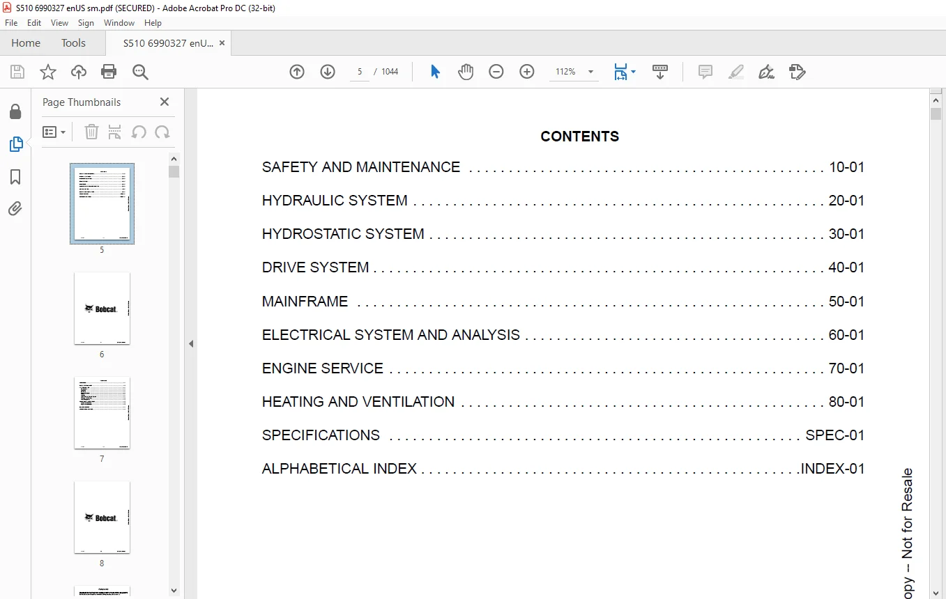
TABLE OF CONTENTS:
Bobcat S510 Skid-Steer Loader Service Manual 6990327 (03-19) – PDF DOWNLOAD
MAINTENANCE SAFETY 3
CONTENTS 5
FOREWORD 7
FOREWORD 9
SAFETY INSTRUCTIONS 11
FIRE PREVENTION 13
Maintenance 13
Operation 13
Electrical 13
Hydraulic System 13
Fueling 13
Starting 13
Spark Arrester Exhaust System 13
Welding And Grinding 14
Fire Extinguishers 14
SERIAL NUMBER LOCATIONS 15
Loader Serial Number 15
Engine Serial Number 15
DELIVERY REPORT 16
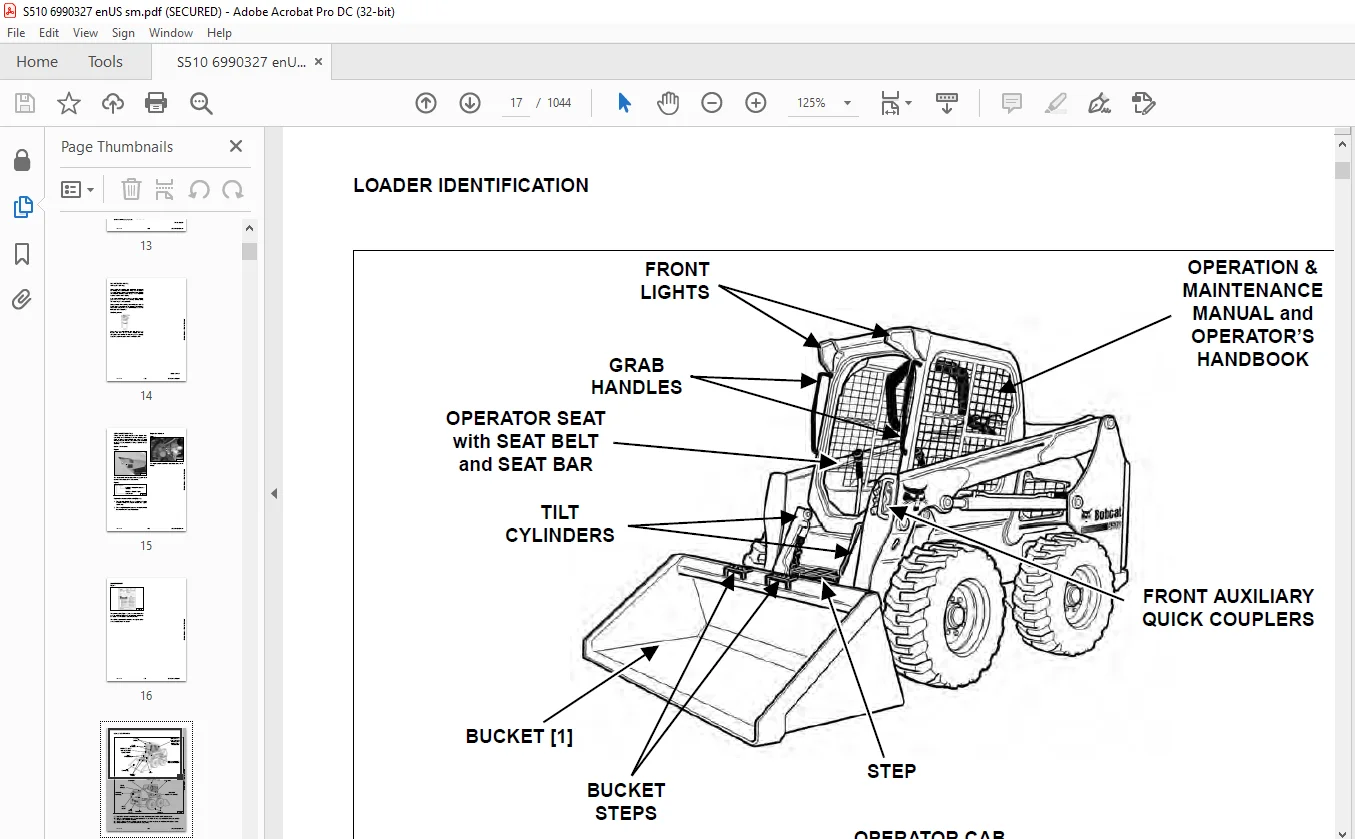
LOADER IDENTIFICATION 17
SAFETY AND MAINTENANCE 19
LIFTING AND BLOCKING THE LOADER 23
Procedure 23
LIFT ARM SUPPORT DEVICE 25
Description 25
Installing 26
Removing 27
OPERATOR CAB 29
Description 29
Raising 30
Lowering 31
Cab Door Sensor 32
Special Applications Kit 32
Special Applications Kit Inspection And Maintenance 32
Forestry Door And Window Kit 33
Forestry Door And Window Kit Inspection And Maintenance 33
TRANSPORTING THE LOADER ON A TRAILER 35
Loading And Unloading 35
Fastening 35
TOWING THE LOADER 37
Procedure 37
REMOTE START TOOL KIT – MEL1563 39
Remote Start Tool – MEL1563 39
Service Tool Harness Communicator – MEL1566 41
Remote Start Procedure 41
REMOTE START TOOL (SERVICE TOOL) KIT – 7217666 45
Description 45
Remote Start Tool (Service Tool) – 7022042 46
Loader Service Tool Harness – 6689747 47
Computer Service Tool Harness – 6689746 48
Remote Start Procedure 49
SERVICE SCHEDULE 53
Maintenance Intervals 53
ENGINE AIR CLEANER 55
Replacing Filters 55
ENGINE COOLING SYSTEM (EARLIER MODELS) 57
Maintenance Platform 57
Cleaning 58
Checking And Adding Coolant 59
Removing And Replacing Coolant 60
ENGINE COOLING SYSTEM (LATER MODELS) 61
Maintenance Platform 61
Cleaning 61
Checking And Adding Coolant 63
Removing And Replacing Coolant 64
FUEL SYSTEM 67
Fuel Specifications 67
Biodiesel Blend Fuel 67
Filling The Fuel Tank 68
Fuel Filter 69
Removing Air From The Fuel System 70
ENGINE LUBRICATION SYSTEM 71
Checking And Adding Engine Oil 71
Engine Oil Chart 71
Removing And Replacing Oil And Filter 72
HYDRAULIC / HYDROSTATIC SYSTEM (EARLIER MODELS) 73
Checking And Adding Fluid 73
Hydraulic / Hydrostatic Fluid Chart 73
Removing And Replacing Hydraulic Fluid 74
Removing And Replacing Hydraulic / Hydrostatic Filter 76
Removing And Replacing Hydraulic Charge Filter 77
Replacing Reservoir Breather Cap 78
HYDRAULIC / HYDROSTATIC SYSTEM (LATER MODELS) 79
Checking And Adding Fluid 79
Hydraulic / Hydrostatic Fluid Chart 79
Removing And Replacing Hydraulic Fluid 80
Removing And Replacing Hydraulic / Hydrostatic Filter 82
Removing And Replacing Hydraulic Charge Filter 83
Replacing Reservoir Breather Cap 84
FINAL DRIVE TRANSMISSION (CHAINCASE) 85
Checking And Adding Fluid 85
Removing And Replacing Fluid 85
BOB-TACH (HAND LEVER) 87
Inspection And Maintenance 87
BOB-TACH (POWER) 89
Inspection And Maintenance 89
LUBRICATING THE LOADER 91
Lubrication Locations 91
TIRE MAINTENANCE 95
Wheel Nuts 95
Rotating 95
Mounting 96
SPARK ARRESTER MUFFLER 97
Cleaning Procedure 97
PIVOT PINS 99
Inspection And Maintenance 99
LOADER STORAGE AND RETURN TO SERVICE 101
Storage 101
Return To Service 101
STOPPING THE ENGINE AND LEAVING THE LOADER 103
Procedure 103
EMERGENCY EXIT 105
Rear Window Identification 105
Rear Window Removal (Latches) 105
Rear Window Removal (Rubber Cord) 105
External Access (Rear Window With Latches) 106
External Access (Rear Window With Rubber Cord) 106
Front Door 106
SEAT BELT 109
Inspection And Maintenance 109
HYDRAULIC SYSTEM 111
HYDRAULIC/HYDROSTATIC SCHEMATIC 115
HYDRAULIC SYSTEM INFORMATION 123
Glossary Of Hydraulic / Hydrostatic Symbols 123
Troubleshooting 127
CYLINDER (LIFT) 129
Testing 129
Removal And Installation 130
Parts Identification 133
Disassembly 134
Assembly 136
CYLINDER (TILT) 139
Testing 139
Removal And Installation 140
Base End Pivot Pin Removal And Installation 141
Parts Identification 142
Disassembly 143
Assembly 145
CYLINDER (BOB-TACH) 149
Testing 149
Removal And Installation 150
Parts Identification 151
Disassembly 152
Assembly 154
MAIN RELIEF VALVE 157
Description 157
Testing 158
Adjusting 160
Removal And Installation 161
HYDRAULIC CONTROL VALVE (STANDARD) 163
Description 163
Removal And Installation 164
Mount Bracket Removal And Installation 167
Identification Chart 168
Lift Load Check Valve Removal And Installation 169
Load Check Valve Removal And Installation (Tilt And Auxiliary) 170
Anti-Cavitation Valve Removal And Installation (Lift, Rod End) 171
Port Relief / Anti-Cavitation Valve Removal And Installation (Lift, Base End) 171
Port Relief / Anti-Cavitation Valve Removal And Installation (Tilt, Base End) 172
Port Relief / Anti-Cavitation Valve Removal And Installation (Tilt, Rod End) 172
Port Relief Valve Removal And Installation 173
Plug Removal And Installation 175
Rubber Boot Removal And Installation 176
End Cap Block Removal And Installation 176
Lift Spool And Detent Removal And Installation 177
Tilt Spool Removal And Installation 185
Auxiliary Spool Removal And Installation 187
Auxiliary Solenoid Removal And Installation 188
Solenoid Removal And Installation 189
Lock Valve Removal And Installation 190
Lift Arm Bypass Orifice Removal And Installation 192
Main Relief Valve Removal And Installation 192
Check Valve Removal And Installation 193
HYDRAULIC CONTROL VALVE (ACS) OR (SJC) 195
Description 195
Removal And Installation 195
Actuator Removal And Installation (In Loader) 199
Actuator Removal And Installation (Out Of Loader) 201
Identification Chart 204
Mount Bracket Removal And Installation 205
Lift Load Check Valve Removal And Installation 205
Load Check Valve Removal And Installation (Tilt And Auxiliary) 206
Anti-Cavitation Valve Removal And Installation (Lift, Rod End) 207
Port Relief / Anti-Cavitation Valve Removal And Installation (Lift, Base End) 207
Port Relief / Anti-Cavitation Valve Removal And Installation (Tilt, Base End) 208
Port Relief / Anti-Cavitation Valve Removal And Installation (Tilt, Rod End) 208
Port Relief Valve Removal And Installation 209
Plug Removal And Installation 211
End Cap Block Removal And Installation 212
Lift Spool Removal And Installation 212
Lift Spool Disassembly And Assembly 214
Tilt Spool Removal And Installation 215
Auxiliary Spool Removal And Installation 217
Auxiliary Solenoid Removal And Installation 218
Solenoid Removal And Installation 219
Lock Valve Removal And Installation 220
Lift Arm Bypass Orifice Removal And Installation 222
Main Relief Valve Removal And Installation 222
Check Valve Removal And Installation 223
LIFT ARM BYPASS CONTROL VALVE 225
Description 225
Testing 225
Removal And Installation 226
Bracket Removal And Installation 227
Disassembly And Assembly 227
HYDRAULIC PUMP 229
Description 229
Pump Test At Quick Couplers 230
Direct Pump Test (Standard Section) 232
Direct Pump Test (Charge Section) 234
Removal And Installation 236
Hydraulic Pump Startup 238
Parts Identification 239
Disassembly And Assembly 240
HYDRAULIC / HYDROSTATIC FILTERS 241
Description 241
Housing Removal And Installation 241
HYDRAULIC FLUID RESERVOIR 243
Description 243
Removal And Installation 243
Hydraulic Fluid Screen 244
OIL COOLER (EARLIER MODELS) 245
Description 245
Removal And Installation 245
OIL COOLER (LATER MODELS) 247
Removal And Installation 247
BUCKET POSITION VALVE 249
Description 249
Solenoid Removal And Installation 249
Solenoid Testing 250
Removal And Installation 251
Disassembly And Assembly 253
REAR AUXILIARY DIVERTER VALVE 255
Description 255
Solenoid Testing 255
Removal And Installation 256
Disassembly And Assembly 257
BOB-TACH (POWER) BLOCK 263
Description 263
Removal And Installation 263
Disassembly And Assembly 265
FRONT AUXILIARY HYDRAULIC COUPLER BLOCK 273
Description 273
Removal And Installation 273
Disassembly And Assembly 273
HYDROSTATIC SYSTEM 275
HYDROSTATIC SYSTEM INFORMATION 277
Description 277
Troubleshooting 278
HYDROSTATIC DRIVE MOTOR 279
Description 279
Removal And Installation 279
Parts Identification 282
Disassembly And Assembly 283
HYDROSTATIC DRIVE MOTOR (TWO-SPEED) 289
Description 289
Removal And Installation (Left Side) 290
Removal And Installation (Right Side) 293
Parts Identification 296
Disassembly 297
Assembly 310
HYDROSTATIC MOTOR CARRIER 325
Description 325
Shaft Seal Removal And Installation 326
Removal And Installation 328
Parts Identification 330
Disassembly 331
Assembly 333
HYDROSTATIC MOTOR CARRIER (TWO-SPEED) 337
Description 337
Shaft Seal Removal And Installation 338
Removal And Installation 340
Parts Identification 342
Disassembly 343
Assembly 345
CHARGE PRESSURE 349
Description 349
Testing 350
Adjusting 351
Sender Removal And Installation 353
HYDROSTATIC PUMP 355
Description 355
Removal And Installation 356
Hydrostatic Pump Startup 357
Replenishing / High Pressure Relief Valve Removal And Installation 358
Parts Identification (Left Half) 359
Parts Identification (Right Half) 360
Disassembly 361
Assembly 368
HYDROSTATIC PUMP (SJC) 375
Description 375
Hydraulic Controller Removal And Installation 376
Removal And Installation 378
Hydrostatic Pump Startup 380
Parts Identification 381
High Pressure Relief And Bypass Valve 382
Charge Relief Valve 383
Disassembly And Assembly 384
Mechanical Neutral Adjustment 397
Hydraulic Controller Neutral Adjustment 400
DRIVE BELT 403
Belt Adjustment 403
Belt Replacement 404
TWO-SPEED 407
Valve Block Removal And Installation 407
Valve Block Disassembly And Assembly 408
DRAIN MANIFOLD 409
Description 409
Drain Manifold Removal And Installation 409
DRIVE SYSTEM 411
BRAKE 413
Description 413
Disc Removal And Installation 413
DRIVE COMPONENTS 415
Description 415
Axle Seal Removal And Installation 416
Axle, Sprocket And Bearings Removal And Installation 418
Chain Removal And Installation 423
CHAINCASE 425
Description 425
Front Cover Removal And Installation 425
Center Cover Removal And Installation 426
Rear Cover Removal And Installation 427
MAINFRAME 429
SEAT BAR 433
Description 433
Removal And Installation 433
Disassembly And Assembly 434
Compression Spring Disassembly And Assembly 435
OPERATOR CAB 437
Gas Spring Removal And Installation 437
Gas Spring Bracket Disassembly And Assembly 438
Removal And Installation 438
OPERATOR SEAT 441
Removal And Installation 441
Seat Belt Removal And Installation (Retractable) 441
Seat Belt And Bracket Removal And Installation (Standard) 442
Seat Belt Bracket Removal And Installation 442
OPERATOR SEAT (SUSPENSION) 443
Removal And Installation 443
Slide Rail Removal And Installation 443
Seat Belt Removal And Installation 444
Lower Cushion Removal 444
Lower Cushion Installation 445
Back Cushion Removal And Installation 445
Shock Removal And Installation 446
3-Point Seat Belt Removal And Installation 446
BOB-TACH (HAND LEVER) 449
Description 449
Removal And Installation 449
Lever And Wedge Disassembly And Assembly 451
Pivot Pin Bushing And Seal Removal And Installation 453
BOB-TACH (POWER) 455
Description 455
Removal And Installation 455
Lever And Wedge Disassembly And Assembly 458
Pivot Pin Bushing And Seal Removal And Installation 459
LIFT ARMS 461
Removal And Installation 461
REAR GRILLE 463
Removing 463
Installing 463
REAR DOOR (TAILGATE) 465
Removal And Installation 465
Striker Removal And Installation 466
Striker Disassembly And Assembly 466
Striker Adjusting 467
Latch Removal And Installation 467
FUEL TANK 469
Removal And Installation 469
Fuel Level Sender Removal And Installation 472
Fuel Fill Screen Removal And Installation 472
CONTROL PEDALS AND LINKAGES 473
Description 473
Pedal Removal And Installation 473
Linkage Removal And Installation 474
Pedal (Adjusting) 475
Floor Pan Removal And Installation 476
CONTROL PEDALS AND LINKAGES (ACS) 477
Description 477
Pedal Removal And Installation 477
Linkage Removal And Installation 478
Pedal (Adjusting) 478
Floor Pan Removal And Installation 479
CONTROL PANEL 481
Description 481
Removal And Installation 482
Disassembly And Assembly 483
Linkage Removal And Installation 485
Pintle Arm Disassembly And Assembly 489
Linkage Neutral (Adjusting) 490
Linkage Travel (Adjusting) 494
Shock Removal And Installation 498
CONTROL PANEL (SJC) 499
Description 499
Removal And Installation 499
CONTROL HANDLE / LEVER 501
Description 501
Lever Removal And Installation 501
Boot Removal And Installation 502
CONTROL HANDLE / LEVER (ACS) 503
Description 503
Handle Sensor Removal And Installation 503
Handle Removal And Installation 506
Handle Disassembly And Assembly 507
Lever Removal And Installation 507
Boot Removal And Installation 508
CONTROL HANDLE / LEVER (SJC) 509
Description 509
Joystick Testing 509
Joystick Removal And Installation 510
ACCESS PANEL (INSIDE) 511
Removal And Installation (Left) 511
Removal And Installation (Right) 511
ACCESS PANEL (INSIDE) (SJC) 513
Removal And Installation (Left) 513
Removal And Installation (Right) 513
WINDOW (REAR) 515
Removal And Installation 515
Disassembly And Assembly 515
WINDOW (TOP) 517
Removal And Installation 517
WINDOW (SIDE) 519
Removal And Installation 519
CAB DOOR 521
Description 521
Removal And Installation 521
Disassembly And Assembly 522
Aligning 523
Adjusting 524
Checking Operation 524
ARMREST 525
Description 525
Removal And Installation 526
Disassembly And Assembly 527
LEFT SIDE LOWER PANEL 529
Removal And Installation 529
Disassembly And Assembly 531
RIGHT SIDE LOWER PANEL 533
Removal And Installation 533
Disassembly And Assembly 534
HEADLINER 537
Removal And Installation 537
ELECTRICAL SYSTEM AND ANALYSIS 539
ELECTRICAL SCHEMATIC 543
ELECTRICAL SYSTEM INFORMATION 721
Glossary Of Electrical Symbols 721
Standard Cab Harness Connectors 724
Deluxe Cab Harness Connectors 725
Mainframe Harness Connectors – Manual Controls 726
Mainframe Harness Connectors – SJC 727
Description 728
Troubleshooting 729
Fuse And Relay Location / Identification 730
Solenoid Testing 732
BATTERY 733
Removal And Installation 733
Servicing 734
Using A Booster Battery (Jump Starting) 735
ALTERNATOR BELT 737
Belt Adjustment 737
Belt Replacement 737
Alternator Voltage Testing 738
Low Voltage Testing 738
High Voltage Testing 739
Removal And Installation 740
Parts Identification 741
STARTER 743
Testing 743
Removal And Installation 743
Parts Identification 744
INSTRUMENT PANELS 745
Left Panel 745
Display Screen 747
Right Panel (Standard Key Panel) 748
Right Panel (Keyless Start Panel) 749
Right Panel (Deluxe Instrumentation Panel) 750
Left Switch Panel 752
Right Switch Panel 752
Left Side Lower Panel 753
Right Side Lower Panel 753
Left Panel Removal And Installation 754
Right Panel (Standard Key Panel) Removal And Installation 754
Right Panel (Keyless Start Panel) Removal And Installation 755
Right Panel (Deluxe Instrumentation Panel) Removal And Installation 755
Key Switch Disassembly And Assembly 756
Alarm Disassembly And Assembly 756
Left Switch Panel Removal And Installation 757
Right Switch Panel Removal And Installation 757
LIGHTS 759
Front Removal And Installation 759
Rear Removal And Installation 760
Cab Light Removal And Installation 760
BOBCAT CONTROLLERS (GATEWAY AND AUXILIARY) 761
Description 761
Connector Identification 762
Removal And Installation 768
BOBCAT CONTROLLER (ACS) 769
Description 769
Connector And Wire Identification 770
Removal And Installation 771
BOBCAT CONTROLLER (SJC) (DRIVE) 773
Description 773
Connector Identification 774
Removal And Installation 776
DIAGNOSTIC SERVICE CODES 777
Viewing Service Codes 777
Service Codes List 778
BOBCAT INTERLOCK CONTROL SYSTEM (BICS™) 785
Description 785
Inspecting The BICS™ (Engine STOPPED – Key ON) 786
Inspecting Deactivation Of The Auxiliary Hydraulics System (Engine STOPPED – Key ON) 786
Inspecting The Seat Bar Sensor (Engine RUNNING) 786
Inspecting The Traction Lock (Engine RUNNING) 786
Inspecting The Lift Arm Bypass Control 786
Inspecting Deactivation Of Lift And Tilt Functions (ACS And SJC) 786
Troubleshooting 787
SEAT BAR SENSOR 789
Description 789
Troubleshooting 789
Testing 790
Removal 791
Installation 793
Bobcat Interlock Control System (BICS™) Circuit Test 794
TRACTION LOCK 797
Description 797
Troubleshooting 798
Inspecting 799
CONTROL SYSTEM (ACS) 801
Description 801
Troubleshooting 802
Handle Sensor Connector Disassembly And Assembly 803
Switch Handle Removal 804
Switch Handle Installation 806
Actuator Connector Disassembly And Assembly 809
Handle Lock Solenoid Removal And Installation 810
Handle Lock Solenoid Disassembly And Assembly 810
Foot Sensor Removal And Installation 811
Foot Sensor Disassembly And Assembly 812
Foot Sensor Lock Solenoid Removal And Installation 812
ELECTRICAL / HYDRAULIC CONTROLS 813
Identification Chart 813
Description 814
Identification Chart ACD Group 0 815
Identification Chart ACD Group 1 816
Identification Chart ACD Group 2 817
Identification Chart ACD Group 3 818
ELECTRICAL / HYDRAULIC CONTROLS (ACS) 819
Identification Chart 819
Description 820
Identification Chart ACD Group 0 821
Identification Chart ACD Group 1 822
Identification Chart ACD Group 2 823
Identification Chart ACD Group 3 824
ELECTRICAL / HYDRAULIC CONTROLS (SJC) 825
Identification Chart 825
Description 826
Identification Chart ACD Group 0 827
Identification Chart ACD Group 1 828
Identification Chart ACD Group 2 829
Identification Chart ACD Group 3 830
SERVICE PC (LAPTOP COMPUTER) 831
Connecting Remote Start Tool 831
Connecting Remote Start Tool (Service Tool) 831
CALIBRATION 833
Description 833
Actuator Testing 833
Lift And Tilt Calibration (SJC) 836
Hydrostatic Pump Calibration (SJC) 838
Lift And Tilt Calibration (ACS) 843
STEERING DRIFT COMPENSATION 845
Description 845
Operation 845
FLYWHEEL RPM SENSOR 847
Description 847
Removal 847
Installation 848
CONTROL PANEL SETUP 849
Right Panel Setup (Deluxe Instrumentation Panel) 849
PASSWORD SETUP (DELUXE INSTRUMENTATION PANEL) 853
Password Description 853
Changing The Owner Password 853
Changing The User Passwords 854
Password Lockout Feature 854
PASSWORD SETUP (KEYLESS START PANEL) 855
Password Description 855
Changing The Owner Password 855
Password Lockout Feature 855
MAINTENANCE CLOCK 857
Description 857
Setup 858
Reset 861
BACK-UP ALARM SYSTEM 863
Description 863
Inspection 863
Adjusting Switch Position 864
Troubleshooting (Standard And ACS) 865
Troubleshooting (Joystick) 866
Alarm Removal And Installation 867
Switch Removal And Installation 867
FRONT HORN 869
Removal And Installation 869
Troubleshooting 870
Troubleshooting (Joystick) 871
ENGINE SERVICE 873
ENGINE INFORMATION 877
Description 877
Specifications 878
Torque Values 881
Troubleshooting 881
Engine Removal And Installation 883
Engine Mount Replacement 892
Compression – Testing 893
ENGINE SPEED CONTROL (HAND) 895
Removal And Installation 895
Disassembly And Assembly 895
Cable Removal And Installation 896
ENGINE SPEED CONTROL (FOOT) 897
Removal And Installation 897
Disassembly And Assembly 898
MUFFLER 901
Removal And Installation 901
AIR CLEANER 903
Housing Removal And Installation 903
ENGINE COOLING SYSTEM (EARLIER MODELS) 905
Radiator Removal And Installation 905
Hydraulic Fan Description 907
Fan Duct Removal And Installation 907
Hydraulic Fan Motor Assembly Removal And Installation 908
Hydraulic Fan Motor Removal And Installation 909
Hydraulic Fan Motor Disassembly And Assembly 911
Blower Housing Removal And Installation 912
Water Pump Removal And Installation 913
Water Pump Disassembly And Assembly 913
Thermostat Housing Removal And Installation 914
Thermostat – Testing 915
ENGINE COOLING SYSTEM (LATER MODELS) 917
Radiator / Oil Cooler Removal And Installation 917
Hydraulic Fan Description 920
Fan Duct Removal And Installation 920
Hydraulic Fan Motor Assembly Removal And Installation 921
Fan Removal And Installation 922
Hydraulic Fan Motor Removal And Installation 923
Hydraulic Fan Disassembly And Assembly 924
Blower Housing Removal And Installation 929
Water Pump Removal And Installation 930
Water Pump Disassembly And Assembly 930
Thermostat Housing Removal And Installation 931
Thermostat – Testing 932
LUBRICATION SYSTEM 933
Oil Pan Removal And Installation 933
Relief Valve – Inspection 933
Oil Pump Removal And Installation 934
Oil Pump Inspection 934
Engine Oil Pressure – Testing 935
FUEL SYSTEM 937
Fuel Shutoff Solenoid – Testing 937
Fuel Shutoff Solenoid Removal And Installation 937
Fuel Injection Pump – Testing 938
Fuel Injection Pump Removal And Installation 939
Governor Disassembly And Assembly 943
Fuel Camshaft Removal And Installation 944
Fuel Injection Pump – Timing 944
Fuel Injector Removal And Installation 946
Fuel Injector Nozzle Pressure – Checking 947
Nozzle Spray Condition 948
Valve Seat Tightness 948
CYLINDER HEAD 949
Glow Plugs – Testing 949
Glow Plugs Removal And Installation 949
Valve Clearance Adjustment 950
Valve Timing – Inspecting 951
Cylinder Head Removal And Installation 952
Cylinder Head Disassembly And Assembly 955
Cylinder Head – Servicing 955
Cylinder Head Top Clearance 956
Valve Guide – Inspecting 956
Valve Guide Removal And Installation 957
Reconditioning The Valve And Valve Seat 957
Valve Spring 959
Valve Tappets 960
Rocker Arm And Shaft – Inspecting 960
Push Rod Alignment – Inspecting 961
CRANKSHAFT AND PISTONS 963
Piston And Connecting Rod Removal And Installation 963
Piston And Connecting Rod – Servicing 964
Cylinder Bore – Inspecting 967
Connecting Rod Alignment 967
Crankshaft Gear Removal And Installation 968
Crankshaft And Bearings Removal And Installation 968
Crankshaft And Bearings – Servicing 970
CAMSHAFT AND TIMING GEARS 975
Timing Gearcase Cover Removal And Installation 975
Timing Gears Backlash – Inspection 977
Idler Gear And Camshaft Removal And Installation 978
Camshaft – Servicing 979
Idler Gear And Shaft – Servicing 980
FLYWHEEL AND HOUSING 981
Flywheel Removal And Installation 981
Ring Gear Removal And Installation 981
Housing Removal And Installation 982
HEATING AND VENTILATION 985
REGULAR MAINTENANCE 987
Filters 987
Heater Coil 988
TROUBLESHOOTING 989
Blower Motor Does Not Operate 989
Blower Motor Operates Normally, But Air Flow Is Insufficient 989
Troubleshooting Tree 990
Electrical System 992
Engine Coolant Bypassing The Heater Valve 995
Heater Valve Not Opening Or Closing 996
HEATER UNIT 997
Removal And Installation 997
HEATER COIL 999
Removal And Installation 999
BLOWER FAN 1001
Removal And Installation 1001
Disassembly And Assembly 1001
HEATER VALVE 1005
Removal And Installation 1005
SPECIFICATIONS 1007
(S510) LOADER SPECIFICATIONS 1009
Machine Dimensions 1009
Performance 1010
Engine 1010
Drive System 1011
Controls 1011
Hydraulic System 1012
Electrical System 1013
Capacities 1013
Tires 1014
Fuel Consumption 1014
Environmental 1014
Temperature Range 1014
TECHNICAL SERVICE GUIDE SPECIFICATIONS 1015
Engine 1015
Engine Torques 1015
Cooling System 1015
Loader Torques 1016
Hydraulic / Hydrostatic System 1016
Fuel Consumption 1016
TORQUE SPECIFICATIONS FOR BOLTS 1017
Torque For General SAE Bolts 1017
Torque For General Metric Bolts 1018
HYDRAULIC CONNECTION SPECIFICATIONS 1019
Straight Thread O-ring Fitting 1019
Flare Fitting 1020
Tubelines And Hoses 1020
HYDRAULIC / HYDROSTATIC FLUID SPECIFICATIONS 1021
Specifications 1021
CONVERSIONS 1023
Decimal And Millimeter Equivalent Chart 1023
U S To Metric Conversion Chart 1023
SERVICE TOOLS REQUIRED 1025
Remote Start Tools 1025
Hydraulic Tools 1026
Mainframe And Drive Tools 1029
Electrical Tools 1032
Engine Tools 1033
HVAC Tools 1038
ALPHABETICAL INDEX 1039
IMAGES PREVIEW OF THE MANUAL:
Contact us: [email protected]
PLEASE NOTE:
- This is the same manual used by the DEALERSHIPS to SERVICE your vehicle.
- The manual can be all yours – Once payment is complete, you will be taken to the download page from where you can download the manual. All in 2-5 minutes time!!
- Need any other service / repair / parts manual, please feel free to contact us at heydownloadss @gmail.com . We may surprise you with a nice offer
S.V