Bobcat S530 Skid-Steer Loader Service Manual 6989670 – PDF DOWNLOAD
$36.95
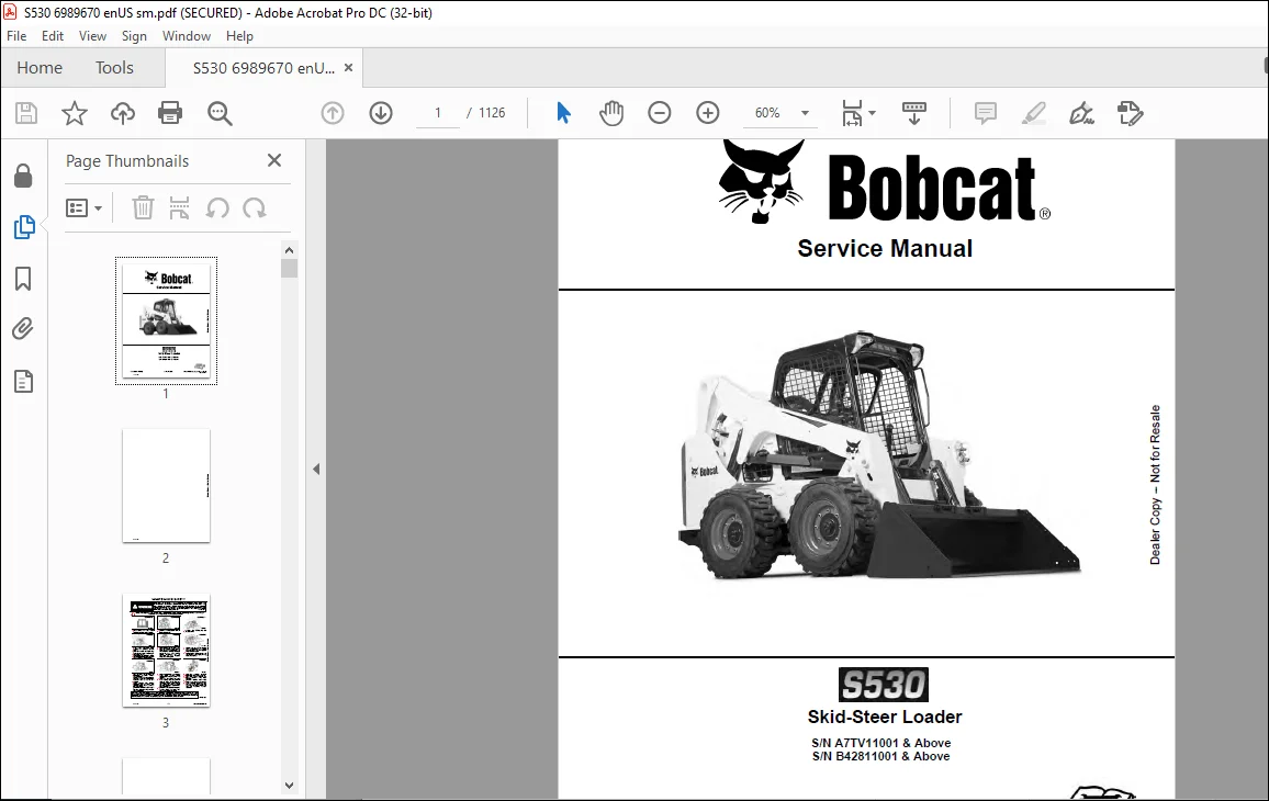
Bobcat S530 Skid-Steer Loader Service Manual 6989670 – PDF DOWNLOAD
S/N A7TV11001 & Above
S/N B42811001 & Above
Description
Bobcat S530 Skid-Steer Loader Service Manual 6989670 – PDF DOWNLOAD
FILE DETAILS:
Bobcat S530 Skid-Steer Loader Service Manual 6989670 – PDF DOWNLOAD
Language : English
Pages : 1126
Downloadable : Yes
File Type : PDF
DESCRIPTION:
Bobcat S530 Skid-Steer Loader Service Manual 6989670 – PDF DOWNLOAD
S/N A7TV11001 & Above
S/N B42811001 & Above
FOREWORD:
This manual is for the Bobcat loader mechanic. It provides necessary servicing and adjustment procedures for the Bobcat loader and its component parts and systems. Refer to the Operation & Maintenance Manual for operating instructions, starting procedure, daily checks, etc.
A general inspection of the following items must be made after the loader has had service or repair:
TABLE OF CONTENTS:
Bobcat S530 Skid-Steer Loader Service Manual 6989670 – PDF DOWNLOAD
MAINTENANCE SAFETY 3
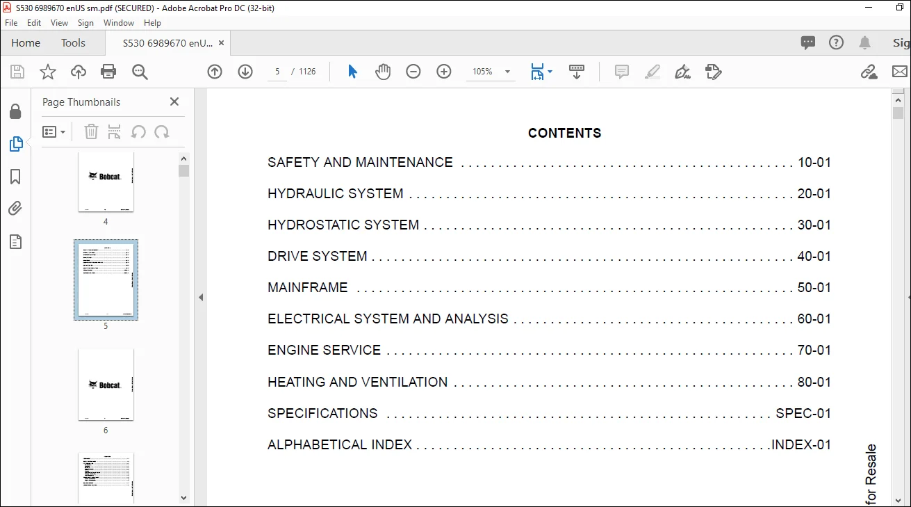
CONTENTS 5
FOREWORD 7
FOREWORD 9
SAFETY INSTRUCTIONS 11
FIRE PREVENTION 13
Maintenance 13
Operation 13
Electrical 13
Hydraulic System 13
Fueling 13
Starting 13
Spark Arrester Exhaust System 13
Welding And Grinding 14
Fire Extinguishers 14
SERIAL NUMBER LOCATIONS 15
Loader Serial Number 15
Engine Serial Number 15
DELIVERY REPORT 16
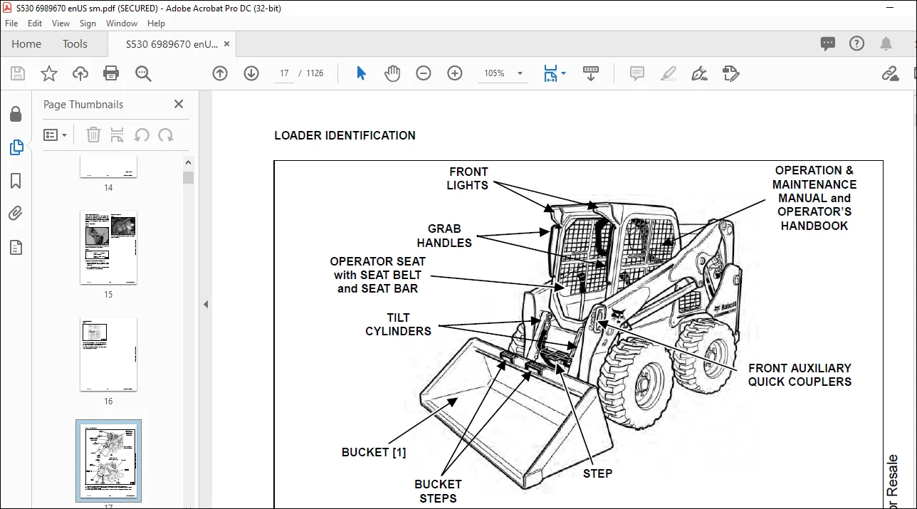
LOADER IDENTIFICATION 17
SAFETY AND MAINTENANCE 19
LIFTING AND BLOCKING THE LOADER 23
Procedure 23
LIFT ARM SUPPORT 25
Description 25
Installing 26
Removing 27
OPERATOR CAB 29
Description 29
Raising 30
Lowering 31
Cab Door Sensor 32
Special Applications Kit 32
Special Applications Kit Inspection And Maintenance 32
Forestry Door And Window Kit 33
Forestry Door And Window Kit Inspection And Maintenance 33
TRANSPORTING THE LOADER ON A TRAILER 35
Loading And Unloading 35
Fastening 35
TOWING THE LOADER 37
Procedure 37
REMOTE START TOOL KIT – MEL1563 39
Remote Start Tool – MEL1563 39
Service Tool Harness Communicator – MEL1566 41
Remote Start Procedure 41
REMOTE START TOOL (SERVICE TOOL) KIT – 7217666 45
Description 45
Remote Start Tool (Service Tool) – 7022042 46
Loader Service Tool Harness – 6689747 47
Computer Service Tool Harness – 6689746 48
Remote Start Procedure 49
SERVICE SCHEDULE 53
Maintenance Intervals 53
ENGINE AIR CLEANER 55
Replacing Filters 55
ENGINE COOLING SYSTEM (EARLIER MODELS) 57
Maintenance Platform 57
Cleaning 58
Checking And Adding Coolant 59
Removing And Replacing Coolant 60
ENGINE COOLING SYSTEM (LATER MODELS) 61
Maintenance Platform 61
Cleaning 61
Checking And Adding Coolant 63
Removing And Replacing Coolant 64
FUEL SYSTEM 67
Fuel Specifications 67
Biodiesel Blend Fuel 67
Filling The Fuel Tank 68
Fuel Filter 69
Removing Air From The Fuel System 70
ENGINE LUBRICATION SYSTEM 71
Checking And Adding Engine Oil 71
Engine Oil Chart 71
Removing And Replacing Oil And Filter 72
HYDRAULIC / HYDROSTATIC SYSTEM (EARLIER MODELS) 73
Checking And Adding Fluid 73
Hydraulic / Hydrostatic Fluid Chart 73
Removing And Replacing Hydraulic Fluid 74
Removing And Replacing Hydraulic / Hydrostatic Filter 76
Removing And Replacing Hydraulic Charge Filter 77
Replacing Reservoir Breather Cap 78
HYDRAULIC / HYDROSTATIC SYSTEM (LATER MODELS) 79
Checking And Adding Fluid 79
Hydraulic / Hydrostatic Fluid Chart 79
Removing And Replacing Hydraulic Fluid 80
Removing And Replacing Hydraulic / Hydrostatic Filter 82
Removing And Replacing Hydraulic Charge Filter 83
Replacing Reservoir Breather Cap 84
FINAL DRIVE TRANSMISSION (CHAINCASE) 85
Checking And Adding Fluid 85
Removing And Replacing Fluid 85
BOB-TACH (HAND LEVER) 87
Inspection And Maintenance 87
BOB-TACH (POWER) 89
Inspection And Maintenance 89
LUBRICATING THE LOADER 91
Lubrication Locations 91
TIRE MAINTENANCE 95
Wheel Nuts 95
Rotating 95
Mounting 96
SPARK ARRESTER MUFFLER 97
Cleaning Procedure 97
PIVOT PINS 99
Inspection And Maintenance 99
LOADER STORAGE AND RETURN TO SERVICE 101
Storage 101
Return To Service 101
STOPPING THE ENGINE AND LEAVING THE LOADER 103
Procedure 103
EMERGENCY EXIT 105
Rear Window Identification 105
Rear Window Removal (Latches) 105
Rear Window Removal (Rubber Cord) 105
External Access (Rear Window With Latches) 106
External Access (Rear Window With Rubber Cord) 106
Front Door 107
SEAT BELT 109
Inspection And Maintenance 109
HYDRAULIC SYSTEM 111
HYDRAULIC / HYDROSTATIC SCHEMATICS 115
HYDRAULIC SYSTEM INFORMATION 135
Glossary Of Hydraulic / Hydrostatic Symbols 135
Troubleshooting 139
CYLINDER (LIFT) 141
Testing 141
Removal And Installation 142
Parts Identification 146
Disassembly 147
Assembly 149
CYLINDER (TILT) 153
Testing 153
Removal And Installation 154
Base End Pivot Pin Removal And Installation 155
Parts Identification 156
Disassembly 157
Assembly 159
CYLINDER (BOB-TACH) 163
Testing 163
Removal And Installation 164
Parts Identification 165
Disassembly 166
Assembly 168
MAIN RELIEF VALVE 171
Description 171
Testing 172
Adjusting 174
Removal And Installation 175
HYDRAULIC CONTROL VALVE (STANDARD) 177
Description 177
Removal And Installation 178
Mount Bracket Removal And Installation 181
Identification Chart 182
Lift Load Check Valve Removal And Installation 183
Load Check Valve Removal And Installation (Tilt And Auxiliary) 184
Anti-Cavitation Valve Removal And Installation (Lift, Rod End) 185
Port Relief / Anti-Cavitation Valve Removal And Installation (Lift, Base End) 185
Port Relief / Anti-Cavitation Valve Removal And Installation (Tilt, Base End) 186
Port Relief / Anti-Cavitation Valve Removal And Installation (Tilt, Rod End) 186
Port Relief Valve Removal And Installation 187
Plug Removal And Installation 189
Rubber Boot Removal And Installation 190
End Cap Block Removal And Installation 190
Lift Spool And Detent Removal And Installation 191
Tilt Spool Removal And Installation 199
Auxiliary Spool Removal And Installation 201
Auxiliary Solenoid Removal And Installation 202
Solenoid Removal And Installation 203
Lock Valve Removal And Installation 204
Lift Arm Bypass Orifice Removal And Installation 206
Main Relief Valve Removal And Installation 206
Check Valve Removal And Installation 207
HYDRAULIC CONTROL VALVE (ACS) OR (SJC) 209
Description 209
Removal And Installation 209
Actuator Removal And Installation (In Loader) 213
Actuator Removal And Installation (Out Of Loader) 215
Identification Chart 218
Mount Bracket Removal And Installation 219
Lift Load Check Valve Removal And Installation 219
Load Check Valve Removal And Installation (Tilt And Auxiliary) 220
Anti-Cavitation Valve Removal And Installation (Lift, Rod End) 221
Port Relief / Anti-Cavitation Valve Removal And Installation (Lift, Base End) 221
Port Relief / Anti-Cavitation Valve Removal And Installation (Tilt, Base End) 222
Port Relief / Anti-Cavitation Valve Removal And Installation (Tilt, Rod End) 222
Port Relief Valve Removal And Installation 223
Plug Removal And Installation 225
End Cap Block Removal And Installation 226
Lift Spool Removal And Installation 226
Lift Spool Disassembly And Assembly 228
Tilt Spool Removal And Installation 229
Auxiliary Spool Removal And Installation 231
Auxiliary Solenoid Removal And Installation 232
Solenoid Removal And Installation 233
Lock Valve Removal And Installation 234
Lift Arm Bypass Orifice Removal And Installation 236
Main Relief Valve Removal And Installation 236
Check Valve Removal And Installation 237
LIFT ARM BYPASS CONTROL VALVE 239
Description 239
Testing 239
Removal And Installation 240
Bracket Removal And Installation 241
Disassembly And Assembly 241
HYDRAULIC PUMP 243
Description 243
Pump Test At Quick Couplers 244
Direct Pump Test (Standard Section) 246
Direct Pump Test (Charge Section) 248
Removal And Installation 250
Hydraulic Pump Startup 252
Parts Identification 253
Disassembly And Assembly 254
HYDRAULIC / HYDROSTATIC FILTERS 255
Description 255
Housing Removal And Installation 255
HYDRAULIC FLUID RESERVOIR 257
Description 257
Removal And Installation 257
Hydraulic Fluid Screen 258
OIL COOLER (EARLIER MODELS) 259
Description 259
Removal And Installation 259
OIL COOLER (LATER MODLES) 261
Removal And Installation 261
BUCKET POSITION VALVE 263
Description 263
Solenoid Removal And Installation 263
Solenoid Testing 264
Removal And Installation 265
Disassembly And Assembly 267
REAR AUXILIARY DIVERTER VALVE 269
Description 269
Solenoid Testing 269
Removal And Installation 270
Disassembly And Assembly 271
BOB-TACH (POWER) BLOCK (S/N A7TV11001 – A7TV13265) 277
Description 277
Removal And Installation 277
Disassembly And Assembly 279
BOB-TACH (POWER) BLOCK (S/N A7TV13266 AND B42811001 & ABOVE) 287
Description 287
Testing Relief Valve 288
Removal And Installation 290
Disassembly And Assembly 292
FRONT AUXILIARY HYDRAULIC COUPLER BLOCK 297
Description 297
Removal And Installation 298
Disassembly And Assembly (FFI/FI) 298
Disassembly And Assembly (FFH/FH) 300
AUTOMATIC RIDE CONTROL 303
Description 303
Removal And Installation 304
Checking The Pressure In The Accumulator 307
Adding Nitrogen To The Accumulator 309
HYDROSTATIC SYSTEM 311
HYDROSTATIC SYSTEM INFORMATION 313
Description 313
Troubleshooting 314
HYDROSTATIC DRIVE MOTOR 315
Description 315
Removal And Installation 315
Parts Identification 318
Disassembly And Assembly 319
HYDROSTATIC DRIVE MOTOR (TWO-SPEED) 325
Description 325
Removal And Installation (Left Side) 326
Removal And Installation (Right Side) 329
Parts Identification 332
Disassembly 333
Assembly 346
HYDROSTATIC MOTOR CARRIER 361
Description 361
Shaft Seal Removal And Installation 362
Removal And Installation 364
Parts Identification 366
Disassembly 367
Assembly 369
HYDROSTATIC MOTOR CARRIER (TWO-SPEED) 373
Description 373
Shaft Seal Removal And Installation 374
Removal And Installation 376
Parts Identification 378
Disassembly 379
Assembly 381
CHARGE PRESSURE 385
Description 385
Testing 386
Adjusting 388
Sender Removal And Installation 390
HYDROSTATIC PUMP 391
Description 391
Removal And Installation 392
Hydrostatic Pump Startup 393
Replenishing / High Pressure Relief Valve Removal And Installation 394
Parts Identification (Left Half) 395
Parts Identification (Right Half) 396
Disassembly 397
Assembly 404
HYDROSTATIC PUMP (SJC) 411
Description 411
Hydraulic Controller Removal And Installation 412
Removal And Installation 414
Hydrostatic Pump Startup 416
Parts Identification 417
High Pressure Relief And Bypass Valve 418
Charge Relief Valve 419
Disassembly And Assembly 420
Mechanical Neutral Adjustment 433
Hydraulic Controller Neutral Adjustment 436
DRIVE BELT 439
Belt Adjustment 439
Belt Replacement 440
TWO-SPEED 443
Valve Block Removal And Installation 443
Valve Block Disassembly And Assembly 444
DRAIN MANIFOLD 445
Description 445
Drain Manifold Removal And Installation 445
DRIVE SYSTEM 447
BRAKE 449
Description 449
Disc Removal And Installation 449
DRIVE COMPONENTS 451
Description 451
Axle Seal Removal And Installation 452
Axle, Sprocket And Bearings Removal And Installation 454
Chain Removal And Installation 459
CHAINCASE 461
Description 461
Front Cover Removal And Installation 461
Center Cover Removal And Installation 462
Rear Cover Removal And Installation 463
MAINFRAME 465
SEAT BAR 469
Description 469
Removal And Installation 469
Disassembly And Assembly 470
Compression Spring Disassembly And Assembly 471
OPERATOR CAB 473
Gas Spring Removal And Installation 473
Gas Spring Bracket Disassembly And Assembly 474
Removal And Installation 474
OPERATOR SEAT 477
Removal And Installation 477
Seat Belt Removal And Installation (Retractable) 477
Seat Belt And Bracket Removal And Installation (Standard) 478
Seat Belt Bracket Removal And Installation 478
OPERATOR SEAT (SUSPENSION) 479
Removal And Installation 479
Slide Rail Removal And Installation 479
Seat Belt Removal And Installation 480
Lower Cushion Removal 480
Lower Cushion Installation 481
Back Cushion Removal And Installation 481
Shock Removal And Installation 482
3-Point Seat Belt Removal And Installation 482
BOB-TACH (HAND LEVER) 485
Description 485
Removal And Installation 485
Lever And Wedge Disassembly And Assembly 487
Pivot Pin Bushing And Seal Removal And Installation 489
BOB-TACH (POWER) 491
Description 491
Removal And Installation 491
Lever And Wedge Disassembly And Assembly 494
Pivot Pin Bushing And Seal Removal And Installation 496
LIFT ARMS 497
Stabilizer Bar Removal And Installation 497
Link Removal And Installation 498
Removal And Installation 499
REAR GRILLE 503
Removing 503
Installing 503
REAR DOOR (TAILGATE) 505
Removal And Installation 505
Striker Removal And Installation 506
Striker Disassembly And Assembly 506
Striker Adjusting 507
Latch Removal And Installation 507
FUEL TANK 509
Removal And Installation 509
Fuel Level Sender Removal And Installation 512
Fuel Fill Screen Removal And Installation 512
CONTROL PEDALS AND LINKAGES 513
Description 513
Pedal Removal And Installation 513
Linkage Removal And Installation 514
Pedal (Adjusting) 515
Floor Pan Removal And Installation 516
CONTROL PEDALS AND LINKAGES (ACS) 517
Description 517
Pedal Removal And Installation 517
Linkage Removal And Installation 518
Pedal (Adjusting) 518
Floor Pan Removal And Installation 519
CONTROL PANEL 521
Description 521
Removal And Installation 522
Disassembly And Assembly 523
Linkage Removal And Installation 525
Pintle Arm Disassembly And Assembly 529
Linkage Neutral (Adjusting) 530
Linkage Travel (Adjusting) 534
Shock Removal And Installation 538
CONTROL PANEL (SJC) 539
Description 539
Removal And Installation 539
CONTROL HANDLE / LEVER 541
Description 541
Lever Removal And Installation 541
Boot Removal And Installation 542
CONTROL HANDLE / LEVER (ACS) 543
Description 543
Handle Sensor Removal And Installation 543
Handle Removal And Installation 546
Handle Disassembly And Assembly 547
Lever Removal And Installation 547
Boot Removal And Installation 548
CONTROL HANDLE / LEVER (SJC) 549
Description 549
Joystick Testing 549
Joystick Removal And Installation 550
ACCESS PANEL (INSIDE) 551
Removal And Installation (Left) 551
Removal And Installation (Right) 551
ACCESS PANEL (INSIDE) (SJC) 553
Removal And Installation (Left) 553
Removal And Installation (Right) 553
WINDOW (REAR) 555
Rear Window Identification 555
Rear Window Removal (Latches) 555
Rear Window Removal (Rubber Cord) 555
Disassembly And Assembly 556
External Access (Rear Window With Latches) 557
External Access (Rear Window With Rubber Cord) 557
WINDOW (TOP) 559
Removal And Installation 559
WINDOW (SIDE) 561
Removal And Installation 561
CAB DOOR 563
Description 563
Removal And Installation 563
Disassembly And Assembly 564
Aligning 565
Adjusting 566
Checking Operation 566
ARMREST 567
Description 567
Removal And Installation 568
Disassembly And Assembly 569
LEFT SIDE LOWER PANEL 571
Removal And Installation 571
Disassembly And Assembly 573
RIGHT SIDE LOWER PANEL 575
Removal And Installation 575
Disassembly And Assembly 576
HEADLINER 579
Removal And Installation 579
ELECTRICAL SYSTEM AND ANALYSIS 581
ELECTRICAL SCHEMATICS 585
ELECTRICAL SYSTEM INFORMATION 793
Glossary Of Electrical Symbols 793
Standard Cab Harness Connectors 796
Deluxe Cab Harness Connectors 797
Mainframe Harness Connectors – Manual Controls 798
Mainframe Harness Connectors – SJC 799
Description 800
Troubleshooting 801
Fuse And Relay Location / Identification 802
Solenoid Testing 804
BATTERY 805
Removal And Installation 805
Servicing 806
Using A Booster Battery (Jump Starting) 807
ALTERNATOR BELT 809
Belt Adjustment 809
Belt Replacement 809
Alternator Voltage Testing 810
Low Voltage Testing 810
High Voltage Testing 811
Removal And Installation 812
Parts Identification 813
STARTER 815
Testing 815
Removal And Installation 815
Parts Identification 816
INSTRUMENT PANELS 817
Left Panel 817
Display Screen 819
Right Panel (Standard Key Panel) 820
Right Panel (Keyless Start Panel) 821
Right Panel (Deluxe Instrumentation Panel) 822
Left Switch Panel 824
Right Switch Panel 824
Left Side Lower Panel 825
Right Side Lower Panel 825
Left Panel Removal And Installation 826
Right Panel (Standard Key Panel) Removal And Installation 826
Right Panel (Keyless Start Panel) Removal And Installation 827
Right Panel (Deluxe Instrumentation Panel) Removal And Installation 827
Key Switch Disassembly And Assembly 828
Alarm Disassembly And Assembly 828
Left Switch Panel Removal And Installation 829
Right Switch Panel Removal And Installation 829
LIGHTS 831
Front Removal And Installation 831
Rear Removal And Installation 832
Cab Light Removal And Installation 832
BOBCAT CONTROLLERS (GATEWAY AND AUXILIARY) 833
Description 833
Connector Identification 834
Removal And Installation 840
BOBCAT CONTROLLER (ACS) 841
Description 841
Connector And Wire Identification 842
Removal And Installation 843
BOBCAT CONTROLLER (SJC) (DRIVE) 845
Description 845
Connector Identification 846
Removal And Installation 848
DIAGNOSTIC SERVICE CODES 849
Viewing Service Codes 849
Service Codes List 850
BOBCAT INTERLOCK CONTROL SYSTEM (BICS™) 857
Description 857
Inspecting The BICS™ (Engine STOPPED – Key ON) 858
Inspecting Deactivation Of The Auxiliary Hydraulics System (Engine STOPPED – Key ON) 858
Inspecting The Seat Bar Sensor (Engine RUNNING) 858
Inspecting The Traction Lock And Parking Brake (Engine RUNNING) 858
Inspecting The Lift Arm Bypass Control 858
Inspecting Deactivation Of Lift And Tilt Functions (ACS And SJC) 858
Troubleshooting 859
SEAT BAR SENSOR 861
Description 861
Troubleshooting 861
Testing 862
Removal 863
Installation 865
Bobcat Interlock Control System (BICS™) Circuit Test 866
TRACTION LOCK 869
Description 869
Troubleshooting 870
Inspecting 871
CONTROL SYSTEM (ACS) 873
Description 873
Troubleshooting 874
Handle Sensor Connector Disassembly And Assembly 875
Switch Handle Removal 876
Switch Handle Installation 878
Actuator Connector Disassembly And Assembly 881
Handle Lock Solenoid Removal And Installation 882
Handle Lock Solenoid Disassembly And Assembly 882
Foot Sensor Removal And Installation 883
Foot Sensor Disassembly And Assembly 884
Foot Sensor Lock Solenoid Removal And Installation 884
ELECTRICAL / HYDRAULIC CONTROLS 885
Identification Chart 885
Description 886
Identification Chart ACD Group 0 887
Identification Chart ACD Group 1 888
Identification Chart ACD Group 2 889
Identification Chart ACD Group 3 890
ELECTRICAL / HYDRAULIC CONTROLS (ACS) 891
Identification Chart 891
Description 892
Identification Chart ACD Group 0 893
Identification Chart ACD Group 1 894
Identification Chart ACD Group 2 895
Identification Chart ACD Group 3 896
ELECTRICAL / HYDRAULIC CONTROLS (SJC) 897
Identification Chart 897
Description 898
Identification Chart ACD Group 0 899
Identification Chart ACD Group 1 900
Identification Chart ACD Group 2 901
Identification Chart ACD Group 3 902
SERVICE PC (LAPTOP COMPUTER) 903
Connecting Remote Start Tool 903
Connecting Remote Start Tool (Service Tool) 903
CALIBRATION 905
Description 905
Actuator Testing 905
Lift And Tilt Calibration (SJC) 908
Hydrostatic Pump Calibration (SJC) 910
Lift And Tilt Calibration (ACS) 915
STEERING DRIFT COMPENSATION (OPERATOR MODE) 917
Description 917
Operation 917
STEERING DRIFT COMPENSATION (SERVICE MODE) 919
Description 919
Operation 919
FLYWHEEL RPM SENSOR 921
Description 921
Removal 921
Installation 922
CONTROL PANEL SETUP 923
Right Panel Setup (Deluxe Instrumentation Panel) 923
PASSWORD SETUP (DELUXE INSTRUMENTATION PANEL) 927
Password Description 927
Changing The Owner Password 927
Changing The User Passwords 928
Password Lockout Feature 928
PASSWORD SETUP (KEYLESS START PANEL) 929
Password Description 929
Changing The Owner Password 929
Password Lockout Feature 929
MAINTENANCE CLOCK 931
Description 931
Setup 932
Reset 935
BACK-UP ALARM SYSTEM 937
Description 937
Inspection 937
Adjusting Switch Position 938
Troubleshooting (Standard And ACS) 939
Troubleshooting (Joystick) 940
Alarm Removal And Installation 941
Switch Removal And Installation 941
FRONT HORN 943
Removal And Installation 943
Troubleshooting 944
Troubleshooting (Joystick) 945
MACHINE IQ 947
Description 947
Removal And Installation 947
Procedure 948
ENGINE SERVICE 949
ENGINE INFORMATION 953
Description 953
Specifications 954
Torque Values 957
Troubleshooting 957
Engine Removal And Installation 959
Engine Mount Replacement 967
Compression – Testing 968
ENGINE SPEED CONTROL (HAND) 971
Removal And Installation 971
Disassembly And Assembly 971
Cable Removal And Installation 972
ENGINE SPEED CONTROL (FOOT) 973
Removal And Installation 973
Disassembly And Assembly 974
MUFFLER 977
Removal And Installation 977
AIR CLEANER 979
Housing Removal And Installation 979
ENGINE COOLING SYSTEM (EARLIER MODELS) 981
Radiator Removal And Installation 981
Hydraulic Fan Description 983
Fan Duct Removal And Installation 983
Hydraulic Fan Motor Assembly Removal And Installation 984
Hydraulic Fan Motor Removal And Installation 985
Hydraulic Fan Motor Disassembly And Assembly 987
Blower Housing Removal And Installation 988
Water Pump Removal And Installation 989
Water Pump Disassembly And Assembly 989
Thermostat Housing Removal And Installation 990
Thermostat – Testing 991
ENGINE COOLING SYSTEM (LATER MODELS) 993
Radiator / Oil Cooler Removal And Installation 993
Hydraulic Fan Description 996
Reversible Hydraulic Fan Description 996
Fan Duct Removal And Installation 996
Hydraulic Fan Motor Assembly Removal And Installation 997
Hydraulic Fan Motor Removal And Installation 998
Hydraulic Fan Motor Disassembly And Assembly 1000
Blower Housing Removal And Installation 1008
Water Pump Removal And Installation 1008
Water Pump Disassembly And Assembly 1008
Thermostat Housing Removal And Installation 1009
Thermostat – Testing 1010
LUBRICATION SYSTEM 1011
Oil Pan Removal And Installation 1011
Relief Valve – Inspection 1011
Oil Pump Removal And Installation 1012
Oil Pump Inspection 1012
Engine Oil Pressure – Testing 1013
FUEL SYSTEM 1015
Fuel Shutoff Solenoid – Testing 1015
Fuel Shutoff Solenoid Removal And Installation 1015
Fuel Injection Pump – Testing 1016
Fuel Injection Pump Removal And Installation 1017
Governor Disassembly And Assembly 1021
Fuel Camshaft Removal And Installation 1022
Fuel Injection Pump – Timing 1022
Fuel Injector Removal And Installation 1024
Fuel Injector Nozzle Pressure – Testing 1025
Nozzle Spray Condition 1026
Valve Seat Tightness 1026
CYLINDER HEAD 1027
Glow Plugs – Testing 1027
Glow Plugs Removal And Installation 1027
Valve Clearance Adjustment 1028
Valve Timing – Inspecting 1029
Cylinder Head Removal And Installation 1030
Cylinder Head Disassembly And Assembly 1033
Cylinder Head – Servicing 1033
Cylinder Head Top Clearance 1034
Valve Guide – Inspecting 1034
Valve Guide Removal And Installation 1035
Reconditioning The Valve And Valve Seat 1035
Valve Spring 1037
Valve Tappets 1038
Rocker Arm And Shaft – Inspecting 1038
Push Rod Alignment – Inspecting 1039
CRANKSHAFT AND PISTONS 1041
Piston And Connecting Rod Removal And Installation 1041
Piston And Connecting Rod – Servicing 1042
Cylinder Bore – Inspecting 1045
Connecting Rod Alignment 1045
Crankshaft Gear Removal And Installation 1046
Crankshaft And Bearings Removal And Installation 1046
Crankshaft And Bearings – Servicing 1048
CAMSHAFT AND TIMING GEARS 1053
Timing Gearcase Cover Removal And Installation 1053
Timing Gears Backlash – Inspection 1055
Idler Gear And Camshaft Removal And Installation 1056
Camshaft – Servicing 1057
Idler Gear And Shaft – Servicing 1058
FLYWHEEL AND HOUSING 1059
Flywheel Removal And Installation 1059
Ring Gear Removal And Installation 1059
Housing Removal And Installation 1060
HEATING AND VENTILATION 1063
REGULAR MAINTENANCE 1065
Filters 1065
Heater Coil 1066
TROUBLESHOOTING 1069
Blower Motor Does Not Operate 1069
Blower Motor Operates Normally, But Air Flow Is Insufficient 1069
Troubleshooting Tree 1070
Electrical System 1072
Engine Coolant Bypassing The Heater Valve 1075
Heater Valve Not Opening Or Closing 1076
HEATER UNIT 1077
Removal And Installation 1077
HEATER COIL 1079
Removal And Installation 1079
BLOWER FAN 1081
Removal And Installation 1081
Disassembly And Assembly 1081
HEATER VALVE 1085
Removal And Installation 1085
EVAPORATOR / HEATER COVER 1087
Removing 1087
Installing 1087
SPECIFICATIONS 1089
(S530) LOADER SPECIFICATIONS 1091
Machine Dimensions 1091
Performance 1092
Engine 1092
Drive System 1093
Controls 1093
Hydraulic System 1094
Electrical System 1095
Capacities 1095
Tires 1096
TECHNICAL SERVICE GUIDE SPECIFICATIONS 1097
Engine 1097
Engine Torques 1097
Cooling System 1097
Loader Torques 1098
Hydraulic / Hydrostatic System 1098
Fuel Consumption 1098
TORQUE SPECIFICATIONS FOR BOLTS 1099
Torque For General SAE Bolts 1099
Torque For General Metric Bolts 1100
HYDRAULIC CONNECTION SPECIFICATIONS 1101
Straight Thread O-ring Fitting 1101
Flare Fitting 1102
Tubelines And Hoses 1102
HYDRAULIC / HYDROSTATIC FLUID SPECIFICATIONS 1103
Specifications 1103
CONVERSIONS 1105
Decimal And Millimeter Equivalent Chart 1105
U S To Metric Conversion Chart 1105
SERVICE TOOLS REQUIRED 1107
Remote Start Tools 1107
Hydraulic Tools 1108
Mainframe And Drive Tools 1111
Electrical Tools 1114
Engine Tools 1115
HVAC Tools 1120
ALPHABETICAL INDEX 1121
IMAGES PREVIEW OF THE MANUAL:
Contact us: [email protected]
PLEASE NOTE:
- This is the same manual used by the DEALERSHIPS to SERVICE your vehicle.
- The manual can be all yours – Once payment is complete, you will be taken to the download page from where you can download the manual. All in 2-5 minutes time!!
- Need any other service / repair / parts manual, please feel free to contact us at heydownloadss @gmail.com . We may surprise you with a nice offer
S.V