Bobcat S530 Skid-Steer Loader Service Manual 6990328 – PDF DOWNLOAD
$36.95
Bobcat S530 Skid-Steer Loader Service Manual 6990328 – PDF DOWNLOAD
S/N A7TW11001 & Above
S/N AZN711001 & Above
S/N ATZD11001 & Above
S/N AZN611001 & Above
Description
Bobcat S530 Skid-Steer Loader Service Manual 6990328 – PDF DOWNLOAD
FILE DETAILS:
Bobcat S530 Skid-Steer Loader Service Manual 6990328 – PDF DOWNLOAD
Language : English
Pages : 1082
Downloadable : Yes
File Type : PDF
DESCRIPTION:
Bobcat S530 Skid-Steer Loader Service Manual 6990328 – PDF DOWNLOAD
S/N A7TW11001 & Above
S/N AZN711001 & Above
S/N ATZD11001 & Above
S/N AZN611001 & Above
FOREWORD:
This manual is for the Bobcat loader mechanic. It provides necessary servicing and adjustment procedures for the Bobcat loader and its component parts and systems. Refer to the Operation & Maintenance Manual for operating instructions, starting procedure, daily checks, etc.
A general inspection of the following items must be made after the loader has had service or repair:
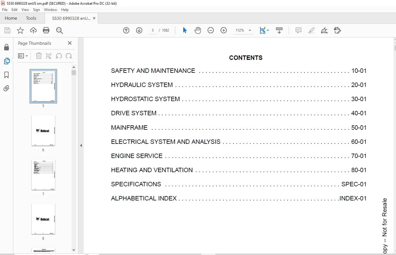
TABLE OF CONTENTS:
Bobcat S530 Skid-Steer Loader Service Manual 6990328 – PDF DOWNLOAD
MAINTENANCE SAFETY 3
CONTENTS 5
FOREWORD 7
FOREWORD 9
SAFETY INSTRUCTIONS 11
FIRE PREVENTION 13
Maintenance 13
Operation 13
Electrical 13
Hydraulic System 13
Fueling 13
Starting 13
Spark Arrester Exhaust System 13
Welding And Grinding 14
Fire Extinguishers 14
SERIAL NUMBER LOCATIONS 15
Loader Serial Number 15
Engine Serial Number 15
DELIVERY REPORT 16
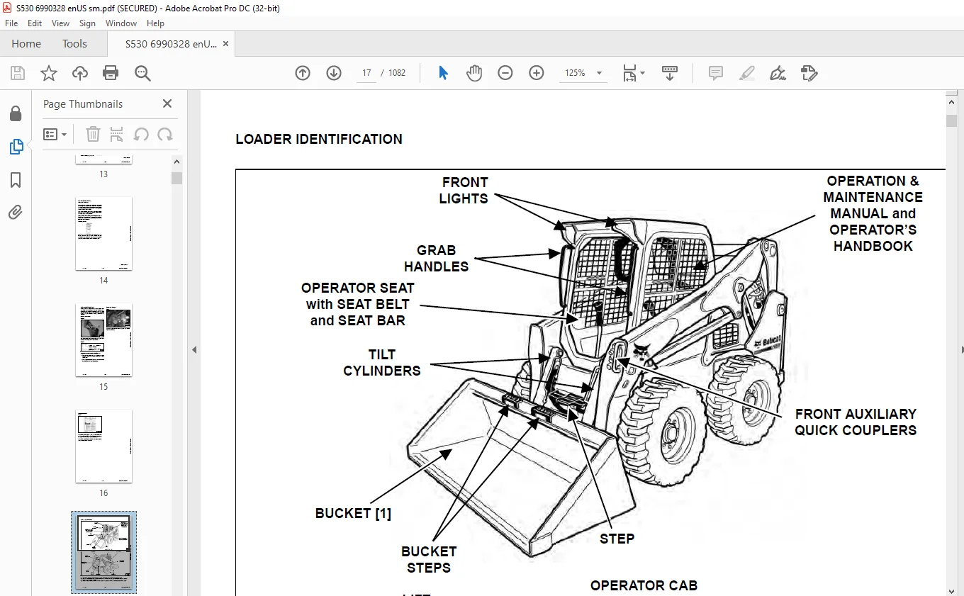
LOADER IDENTIFICATION 17
SAFETY AND MAINTENANCE 19
LIFTING AND BLOCKING THE LOADER 23
Procedure 23
LIFT ARM SUPPORT 25
Description 25
Installing 26
Removing 27
OPERATOR CAB 29
Description 29
Raising 30
Lowering 31
Cab Door Sensor 32
Special Applications Kit 32
Special Applications Kit Inspection And Maintenance 32
Forestry Door And Window Kit 33
Forestry Door And Window Kit Inspection And Maintenance 33
TRANSPORTING THE LOADER ON A TRAILER 35
Loading And Unloading 35
Fastening 35
TOWING THE LOADER 37
Procedure 37
REMOTE START TOOL KIT – MEL1563 39
Remote Start Tool – MEL1563 39
Service Tool Harness Communicator – MEL1566 41
Remote Start Procedure 41
REMOTE START TOOL (SERVICE TOOL) KIT – 7217666 45
Description 45
Remote Start Tool (Service Tool) – 7022042 46
Loader Service Tool Harness – 6689747 47
Computer Service Tool Harness – 6689746 48
Remote Start Procedure 49
SERVICE SCHEDULE 53
Maintenance Intervals 53
ENGINE AIR CLEANER 55
Replacing Filters 55
ENGINE COOLING SYSTEM (EARLIER MODELS) 57
Maintenance Platform 57
Cleaning (Earlier Models) 58
Checking And Adding Coolant 59
Removing And Replacing Coolant 60
ENGINE COOLING SYSTEM (LATER MODELS) 61
Maintenance Platform 61
Cleaning (Later Models) 61
Checking And Adding Coolant 63
Removing And Replacing Coolant 64
FUEL SYSTEM 65
Fuel Specifications 65
Biodiesel Blend Fuel 65
Filling The Fuel Tank 66
Fuel Filter 67
Removing Air From The Fuel System 68
ENGINE LUBRICATION SYSTEM 69
Checking And Adding Engine Oil 69
Engine Oil Chart 69
Removing And Replacing Oil And Filter 70
HYDRAULIC / HYDROSTATIC SYSTEM (EARLIER MODELS) 71
Checking And Adding Fluid 71
Hydraulic / Hydrostatic Fluid Chart 71
Removing And Replacing Hydraulic Fluid 72
Removing And Replacing Hydraulic / Hydrostatic Filter 74
Removing And Replacing Hydraulic Charge Filter 75
Replacing Reservoir Breather Cap 76
HYDRAULIC / HYDROSTATIC SYSTEM (LATER MODELS) 77
Checking And Adding Fluid 77
Hydraulic / Hydrostatic Fluid Chart 77
Removing And Replacing Hydraulic Fluid 78
Removing And Replacing Hydraulic / Hydrostatic Filter 80
Removing And Replacing Hydraulic Charge Filter 81
Replacing Reservoir Breather Cap 82
FINAL DRIVE TRANSMISSION (CHAINCASE) 83
Checking And Adding Fluid 83
Removing And Replacing Fluid 83
BOB-TACH (HAND LEVER) 85
Inspection And Maintenance 85
BOB-TACH (POWER) 87
Inspection And Maintenance 87
LUBRICATING THE LOADER 89
Lubrication Locations 89
TIRE MAINTENANCE 93
Wheel Nuts 93
Rotating 93
Mounting 94
SPARK ARRESTER MUFFLER 95
Cleaning Procedure 95
PIVOT PINS 97
Inspection And Maintenance 97
LOADER STORAGE AND RETURN TO SERVICE 99
Storage 99
Return To Service 99
STOPPING THE ENGINE AND LEAVING THE LOADER 101
Procedure 101
EMERGENCY EXIT 103
Rear Window Identification 103
Rear Window Removal (Latches) 103
Rear Window Removal (Rubber Cord) 103
External Access (Rear Window With Latches) 104
External Access (Rear Window With Rubber Cord) 104
Front Door 105
SEAT BELT 107
Inspection And Maintenance 107
HYDRAULIC SYSTEM 109
HYDRAULIC / HYDROSTATIC SCHEMATICS 113
HYDRAULIC SYSTEM INFORMATION 121
Glossary Of Hydraulic / Hydrostatic Symbols 121
Troubleshooting 125
CYLINDER (LIFT) 127
Testing 127
Removal And Installation 128
Parts Identification 132
Disassembly 133
Assembly 135
CYLINDER (TILT) 139
Testing 139
Removal And Installation 140
Base End Pivot Pin Removal And Installation 141
Parts Identification 142
Disassembly 143
Assembly 145
CYLINDER (BOB-TACH) 149
Testing 149
Removal And Installation 150
Parts Identification 151
Disassembly 152
Assembly 154
MAIN RELIEF VALVE 157
Description 157
Testing 158
Adjusting 160
Removal And Installation 161
HYDRAULIC CONTROL VALVE (STANDARD) 163
Description 163
Removal And Installation 164
Mount Bracket Removal And Installation 167
Identification Chart 168
Lift Load Check Valve Removal And Installation 169
Load Check Valve Removal And Installation (Tilt And Auxiliary) 170
Anti-Cavitation Valve Removal And Installation (Lift, Rod End) 171
Port Relief / Anti-Cavitation Valve Removal And Installation (Lift, Base End) 171
Port Relief / Anti-Cavitation Valve Removal And Installation (Tilt, Base End) 172
Port Relief / Anti-Cavitation Valve Removal And Installation (Tilt, Rod End) 172
Port Relief Valve Removal And Installation 173
Plug Removal And Installation 175
Rubber Boot Removal And Installation 176
End Cap Block Removal And Installation 176
Lift Spool And Detent Removal And Installation 177
Tilt Spool Removal And Installation 185
Auxiliary Spool Removal And Installation 187
Auxiliary Solenoid Removal And Installation 188
Solenoid Removal And Installation 189
Lock Valve Removal And Installation 190
Lift Arm Bypass Orifice Removal And Installation 192
Main Relief Valve Removal And Installation 192
Check Valve Removal And Installation 193
HYDRAULIC CONTROL VALVE (ACS) OR (SJC) 195
Description 195
Removal And Installation 195
Actuator Removal And Installation (In Loader) 199
Actuator Removal And Installation (Out Of Loader) 201
Identification Chart 204
Mount Bracket Removal And Installation 205
Lift Load Check Valve Removal And Installation 205
Load Check Valve Removal And Installation (Tilt And Auxiliary) 206
Anti-Cavitation Valve Removal And Installation (Lift, Rod End) 207
Port Relief / Anti-Cavitation Valve Removal And Installation (Lift, Base End) 207
Port Relief / Anti-Cavitation Valve Removal And Installation (Tilt, Base End) 208
Port Relief / Anti-Cavitation Valve Removal And Installation (Tilt, Rod End) 208
Port Relief Valve Removal And Installation 209
Plug Removal And Installation 211
End Cap Block Removal And Installation 212
Lift Spool Removal And Installation 212
Lift Spool Disassembly And Assembly 214
Tilt Spool Removal And Installation 215
Auxiliary Spool Removal And Installation 217
Auxiliary Solenoid Removal And Installation 218
Solenoid Removal And Installation 219
Lock Valve Removal And Installation 220
Lift Arm Bypass Orifice Removal And Installation 222
Main Relief Valve Removal And Installation 222
Check Valve Removal And Installation 223
LIFT ARM BYPASS CONTROL VALVE 225
Description 225
Testing 225
Removal And Installation 226
Bracket Removal And Installation 227
Disassembly And Assembly 227
HYDRAULIC PUMP 229
Description 229
Pump Test At Quick Couplers 230
Direct Pump Test (Standard Section) 232
Direct Pump Test (Charge Section) 234
Removal And Installation 236
Hydraulic Pump Startup 238
Parts Identification 239
Disassembly And Assembly 240
HYDRAULIC / HYDROSTATIC FILTERS 241
Description 241
Housing Removal And Installation 241
HYDRAULIC FLUID RESERVOIR 243
Description 243
Removal And Installation 243
Hydraulic Fluid Screen 244
OIL COOLER (EARLIER MODELS) 245
Description 245
Removal And Installation 245
OIL COOLER (LATER MODELS) 247
Removal And Installation 247
BUCKET POSITION VALVE 249
Description 249
Solenoid Removal And Installation 249
Solenoid Testing 250
Removal And Installation 251
Disassembly And Assembly 253
REAR AUXILIARY DIVERTER VALVE 255
Description 255
Solenoid Testing 255
Removal And Installation 256
Disassembly And Assembly 257
BOB-TACH (POWER) BLOCK (EARLIER MODELS) 263
Description 263
Removal And Installation 263
Disassembly And Assembly 265
BOB-TACH (POWER) BLOCK (LATER MODELS) 273
Description 273
Testing Relief Valve 274
Removal And Installation 276
Disassembly And Assembly 278
FRONT AUXILIARY HYDRAULIC COUPLER BLOCK 283
Description 283
Removal And Installation 284
Disassembly And Assembly (FFI/FI) 284
Disassembly And Assembly (FFH/FH) 286
AUTOMATIC RIDE CONTROL 289
Description 289
Removal And Installation 290
Checking The Pressure In The Accumulator 293
Adding Nitrogen To The Accumulator 295
HYDROSTATIC SYSTEM 297
HYDROSTATIC SYSTEM INFORMATION 299
Description 299
Troubleshooting 300
HYDROSTATIC DRIVE MOTOR 301
Description 301
Removal And Installation 301
Parts Identification 304
Disassembly And Assembly 305
HYDROSTATIC DRIVE MOTOR (TWO-SPEED) 311
Description 311
Removal And Installation (Left Side) 312
Removal And Installation (Right Side) 315
Parts Identification 318
Disassembly 319
Assembly 332
HYDROSTATIC MOTOR CARRIER 347
Description 347
Shaft Seal Removal And Installation 348
Removal And Installation 350
Parts Identification 352
Disassembly 353
Assembly 355
HYDROSTATIC MOTOR CARRIER (TWO-SPEED) 359
Description 359
Shaft Seal Removal And Installation 360
Removal And Installation 362
Parts Identification 364
Disassembly 365
Assembly 367
CHARGE PRESSURE 371
Description 371
Testing 372
Adjusting 374
Sender Removal And Installation 376
HYDROSTATIC PUMP 377
Description 377
Removal And Installation 378
Hydrostatic Pump Startup 379
Replenishing / High Pressure Relief Valve Removal And Installation 380
Parts Identification (Left Half) 381
Parts Identification (Right Half) 382
Disassembly 383
Assembly 390
HYDROSTATIC PUMP (SJC) 397
Description 397
Hydraulic Controller Removal And Installation 398
Removal And Installation 400
Hydrostatic Pump Startup 402
Parts Identification 403
High Pressure Relief And Bypass Valve 404
Charge Relief Valve 405
Disassembly And Assembly 406
Mechanical Neutral Adjustment 419
Hydraulic Controller Neutral Adjustment 422
DRIVE BELT 425
Belt Adjustment 425
Belt Replacement 426
TWO-SPEED 429
Valve Block Removal And Installation 429
Valve Block Disassembly And Assembly 430
DRAIN MANIFOLD 431
Description 431
Drain Manifold Removal And Installation 432
DRIVE SYSTEM 433
BRAKE 435
Description 435
Disc Removal And Installation 435
DRIVE COMPONENTS 437
Description 437
Axle Seal Removal And Installation 438
Axle, Sprocket And Bearings Removal And Installation 440
Chain Removal And Installation 445
CHAINCASE 447
Description 447
Front Cover Removal And Installation 447
Center Cover Removal And Installation 448
Rear Cover Removal And Installation 449
MAINFRAME 451
SEAT BAR 455
Description 455
Removal And Installation 455
Disassembly And Assembly 456
Compression Spring Disassembly And Assembly 457
OPERATOR CAB 459
Gas Spring Removal And Installation 459
Gas Spring Bracket Disassembly And Assembly 460
Removal And Installation 460
OPERATOR SEAT 463
Removal And Installation 463
Seat Belt Removal And Installation (Retractable) 463
Seat Belt And Bracket Removal And Installation (Standard) 464
Seat Belt Bracket Removal And Installation 464
OPERATOR SEAT (SUSPENSION) 465
Removal And Installation 465
Slide Rail Removal And Installation 465
Seat Belt Removal And Installation 466
Lower Cushion Removal 466
Lower Cushion Installation 467
Back Cushion Removal And Installation 467
Shock Removal And Installation 468
3-Point Seat Belt Removal And Installation 468
BOB-TACH (HAND LEVER) 471
Description 471
Removal And Installation 471
Lever And Wedge Disassembly And Assembly 473
Pivot Pin Bushing And Seal Removal And Installation 475
BOB-TACH (POWER) 477
Description 477
Removal And Installation 477
Lever And Wedge Disassembly And Assembly 480
Pivot Pin Bushing And Seal Removal And Installation 482
LIFT ARMS 483
Stabilizer Bar Removal And Installation 483
Link Removal And Installation 484
Removal And Installation 485
REAR GRILLE 489
Removing 489
Installing 489
REAR DOOR (TAILGATE) 491
Removal And Installation 491
Striker Removal And Installation 492
Striker Disassembly And Assembly 492
Striker Adjusting 493
Latch Removal And Installation 493
FUEL TANK 495
Removal And Installation 495
Fuel Level Sender Removal And Installation 498
Fuel Fill Screen Removal And Installation 498
CONTROL PEDALS AND LINKAGES 499
Description 499
Pedal Removal And Installation 499
Linkage Removal And Installation 500
Pedal (Adjusting) 501
Floor Pan Removal And Installation 502
CONTROL PEDALS AND LINKAGES (ACS) 503
Description 503
Pedal Removal And Installation 503
Linkage Removal And Installation 504
Pedal (Adjusting) 504
Floor Pan Removal And Installation 505
CONTROL PANEL 507
Description 507
Removal And Installation 508
Disassembly And Assembly 509
Linkage Removal And Installation 511
Pintle Arm Disassembly And Assembly 515
Linkage Neutral (Adjusting) 516
Linkage Travel (Adjusting) 520
Shock Removal And Installation 524
CONTROL PANEL (SJC) 525
Description 525
Removal And Installation 525
CONTROL HANDLE / LEVER 527
Description 527
Lever Removal And Installation 527
Boot Removal And Installation 528
CONTROL HANDLE / LEVER (ACS) 529
Description 529
Handle Sensor Removal And Installation 529
Handle Removal And Installation 532
Handle Disassembly And Assembly 533
Lever Removal And Installation 533
Boot Removal And Installation 534
CONTROL HANDLE / LEVER (SJC) 535
Description 535
Joystick Testing 535
Joystick Removal And Installation 536
ACCESS PANEL (INSIDE) 537
Removal And Installation (Left) 537
Removal And Installation (Right) 537
ACCESS PANEL (INSIDE) (SJC) 539
Removal And Installation (Left) 539
Removal And Installation (Right) 539
WINDOW (REAR) 541
Rear Window Identification 541
Rear Window Removal (Latches) 541
Rear Window Removal (Rubber Cord) 541
Disassembly And Assembly 542
External Access (Rear Window With Latches) 543
External Access (Rear Window With Rubber Cord) 543
WINDOW (TOP) 545
Removal And Installation 545
WINDOW (SIDE) 547
Removal And Installation 547
CAB DOOR 549
Description 549
Removal And Installation 549
Disassembly And Assembly 550
Aligning 551
Adjusting 552
Checking Operation 552
ARMREST 553
Description 553
Removal And Installation 554
Disassembly And Assembly 555
LEFT SIDE LOWER PANEL 557
Removal And Installation 557
Disassembly And Assembly 559
RIGHT SIDE LOWER PANEL 561
Removal And Installation 561
Disassembly And Assembly 562
HEADLINER 565
Removal And Installation 565
ELECTRICAL SYSTEM AND ANALYSIS 567
ELECTRICA SCHEMATICS 571
ELECTRICAL SYSTEM INFORMATION 749
Glossary Of Electrical Symbols 749
Standard Cab Harness Connectors 752
Deluxe Cab Harness Connectors 753
Mainframe Harness Connectors – Manual Controls 754
Mainframe Harness Connectors – SJC 755
Description 756
Troubleshooting 757
Fuse And Relay Location / Identification 758
Solenoid Testing 760
BATTERY 761
Removal And Installation 761
Servicing 762
Using A Booster Battery (Jump Starting) 763
ALTERNATOR BELT 765
Belt Adjustment 765
Belt Replacement 765
Alternator Voltage Testing 766
Low Voltage Testing 766
High Voltage Testing 767
Removal And Installation 768
Parts Identification 769
STARTER 771
Testing 771
Removal And Installation 771
Parts Identification 772
INSTRUMENT PANELS IDENTIFICATION 773
Left Panel 773
Display Screen 775
Right Panel (Standard Key Panel) 776
Right Panel (Keyless Start Panel) 777
Right Panel (Deluxe Instrumentation Panel) 778
Left Switch Panel 780
Right Switch Panel 780
Left Side Lower Panel 781
Right Side Lower Panel 781
Left Panel Removal And Installation 782
Right Panel (Standard Key Panel) Removal And Installation 782
Right Panel (Keyless Start Panel) Removal And Installation 783
Right Panel (Deluxe Instrumentation Panel) Removal And Installation 783
Key Switch Disassembly And Assembly 784
Alarm Disassembly And Assembly 784
Left Switch Panel Removal And Installation 785
Right Switch Panel Removal And Installation 785
LIGHTS 787
Front Removal And Installation 787
Rear Removal And Installation 788
Cab Light Removal And Installation 788
BOBCAT CONTROLLERS (GATEWAY AND AUXILIARY) 789
Description 789
Connector Identification 790
Removal And Installation 796
BOBCAT CONTROLLER (ACS) 797
Description 797
Connector And Wire Identification 798
Removal And Installation 799
BOBCAT CONTROLLER (SJC) (DRIVE) 801
Description 801
Connector Identification 802
Removal And Installation 804
DIAGNOSTIC SERVICE CODES 805
Viewing Service Codes 805
Service Codes List 806
BOBCAT INTERLOCK CONTROL SYSTEM (BICS™) 813
Description 813
Inspecting The BICS™ (Engine STOPPED – Key ON) 814
Inspecting Deactivation Of The Auxiliary Hydraulics System (Engine STOPPED – Key ON) 814
Inspecting The Seat Bar Sensor (Engine RUNNING) 814
Inspecting The Traction Lock And Parking Brake (Engine RUNNING) 814
Inspecting The Lift Arm Bypass Control 814
Inspecting Deactivation Of Lift And Tilt Functions (ACS, AHC, And SJC) 814
Troubleshooting 815
SEAT BAR SENSOR 817
Description 817
Troubleshooting 817
Testing 818
Removal 819
Installation 821
Bobcat Interlock Control System (BICS™) Circuit Test 822
TRACTION LOCK 825
Description 825
Troubleshooting 826
Inspecting 827
CONTROL SYSTEM (ACS) 829
Description 829
Troubleshooting 830
Handle Sensor Connector Disassembly And Assembly 831
Switch Handle Removal 832
Switch Handle Installation 834
Actuator Connector Disassembly And Assembly 837
Handle Lock Solenoid Removal And Installation 838
Handle Lock Solenoid Disassembly And Assembly 838
Foot Sensor Removal And Installation 839
Foot Sensor Disassembly And Assembly 840
Foot Sensor Lock Solenoid Removal And Installation 840
ELECTRICAL / HYDRAULIC CONTROLS 841
Identification Chart 841
Description 842
Identification Chart ACD Group 0 843
Identification Chart ACD Group 1 844
Identification Chart ACD Group 2 845
Identification Chart ACD Group 3 846
ELECTRICAL / HYDRAULIC CONTROLS (ACS) 847
Identification Chart 847
Description 848
Identification Chart ACD Group 0 849
Identification Chart ACD Group 1 850
Identification Chart ACD Group 2 851
Identification Chart ACD Group 3 852
ELECTRICAL / HYDRAULIC CONTROLS (SJC) 853
Identification Chart 853
Description 854
Identification Chart ACD Group 0 855
Identification Chart ACD Group 1 856
Identification Chart ACD Group 2 857
Identification Chart ACD Group 3 858
SERVICE PC (LAPTOP COMPUTER) 859
Connecting Remote Start Tool 859
Connecting Remote Start Tool (Service Tool) 859
CALIBRATION 861
Description 861
Actuator Testing 861
Lift And Tilt Calibration (SJC) 864
Hydrostatic Pump Calibration (SJC) 866
Lift And Tilt Calibration (ACS) 871
STEERING DRIFT COMPENSATION (OPERATOR MODE) 873
Description 873
Operation 873
STEERING DRIFT COMPENSATION (SERVICE MODE) 875
Description 875
Operation 875
FLYWHEEL RPM SENSOR 877
Description 877
Removal 877
Installation 878
CONTROL PANEL SETUP 879
Right Panel Setup (Deluxe Instrumentation Panel) 879
PASSWORD SETUP (DELUXE INSTRUMENTATION PANEL) 883
Password Description 883
Changing The Owner Password 883
Changing The User Passwords 884
Password Lockout Feature 884
PASSWORD SETUP (KEYLESS START PANEL) 885
Password Description 885
Changing The Owner Password 885
Password Lockout Feature 885
MAINTENANCE CLOCK 887
Description 887
Setup 888
Reset 891
BACK-UP ALARM SYSTEM 893
Description 893
Inspection 893
Adjusting Switch Position 894
Troubleshooting (Standard And ACS) 895
Troubleshooting (Joystick) 896
Alarm Removal And Installation 897
Switch Removal And Installation 897
FRONT HORN 899
Removal And Installation 899
Troubleshooting 900
Troubleshooting (Joystick) 901
MACHINE IQ 903
Description 903
Removal And Installation 903
Procedure 904
ENGINE SERVICE 905
ENGINE INFORMATION 909
Description 909
Specifications 910
Torque Values 913
Troubleshooting 913
Engine Removal And Installation 915
Engine Mount Replacement 923
Compression – Testing 924
ENGINE SPEED CONTROL (HAND) 927
Removal And Installation 927
Disassembly And Assembly 927
Cable Removal And Installation 928
ENGINE SPEED CONTROL (FOOT) 929
Removal And Installation 929
Disassembly And Assembly 930
MUFFLER 933
Removal And Installation 933
AIR CLEANER 935
Housing Removal And Installation 935
ENGINE COOLING SYSTEM (EARLIER MODELS) 937
Radiator Removal And Installation 937
Hydraulic Fan Description 939
Fan Duct Removal And Installation 939
Hydraulic Fan Motor Assembly Removal And Installation 940
Hydraulic Fan Motor Removal And Installation 941
Hydraulic Fan Motor Disassembly And Assembly 943
Blower Housing Removal And Installation 944
Water Pump Removal And Installation 945
Water Pump Disassembly And Assembly 945
Thermostat Housing Removal And Installation 946
Thermostat – Testing 947
ENGINE COOLING SYSTEM (LATER MODELS) 949
Radiator / Oil Cooler Removal And Installation 949
Reversible Hydraulic Fan Description 952
Fan Duct Removal And Installation 952
Hydraulic Fan Motor Assembly Removal And Installation 953
Hydraulic Fan Motor Removal And Installation 954
Hydraulic Fan Motor Disassembly And Assembly 956
Blower Housing Removal And Installation 964
Water Pump Removal And Installation 964
Water Pump Disassembly And Assembly 965
Thermostat Housing Removal And Installation 966
Thermostat – Testing 967
LUBRICATION SYSTEM 969
Oil Pan Removal And Installation 969
Relief Valve – Inspection 969
Oil Pump Removal And Installation 970
Oil Pump Inspection 970
Engine Oil Pressure – Testing 971
FUEL SYSTEM 973
Fuel Shutoff Solenoid – Testing 973
Fuel Shutoff Solenoid Removal And Installation 973
Fuel Injection Pump – Testing 974
Fuel Injection Pump Removal And Installation 975
Governor Disassembly And Assembly 979
Fuel Camshaft Removal And Installation 980
Fuel Injection Pump – Timing 980
Fuel Injector Removal And Installation 982
Fuel Injector Nozzle Pressure – Testing 983
Nozzle Spray Condition 984
Valve Seat Tightness 984
CYLINDER HEAD 985
Glow Plugs – Testing 985
Glow Plugs Removal And Installation 985
Valve Clearance Adjustment 986
Valve Timing – Inspecting 987
Cylinder Head Removal And Installation 988
Cylinder Head Disassembly And Assembly 991
Cylinder Head – Servicing 991
Cylinder Head Top Clearance 992
Valve Guide – Inspecting 992
Valve Guide Removal And Installation 993
Reconditioning The Valve And Valve Seat 993
Valve Spring 995
Valve Tappets 996
Rocker Arm And Shaft – Inspecting 996
Push Rod Alignment – Inspecting 997
CRANKSHAFT AND PISTONS 999
Piston And Connecting Rod Removal And Installation 999
Piston And Connecting Rod – Servicing 1000
Cylinder Bore – Inspecting 1003
Connecting Rod Alignment 1003
Crankshaft Gear Removal And Installation 1004
Crankshaft And Bearings Removal And Installation 1004
Crankshaft And Bearings – Servicing 1006
CAMSHAFT AND TIMING GEARS 1011
Timing Gearcase Cover Removal And Installation 1011
Timing Gears Backlash – Inspection 1013
Idler Gear And Camshaft Removal And Installation 1014
Camshaft – Servicing 1015
Idler Gear And Shaft – Servicing 1016
FLYWHEEL AND HOUSING 1017
Flywheel Removal And Installation 1017
Ring Gear Removal And Installation 1017
Housing Removal And Installation 1018
HEATING AND VENTILATION 1021
REGULAR MAINTENANCE 1023
Filters 1023
Heater Coil 1024
TROUBLESHOOTING 1025
Blower Motor Does Not Operate 1025
Blower Motor Operates Normally, But Air Flow Is Insufficient 1025
Troubleshooting Tree 1026
Electrical System 1028
Engine Coolant Bypassing The Heater Valve 1031
Heater Valve Not Opening Or Closing 1032
HEATER UNIT 1033
Removal And Installation 1033
HEATER COIL 1035
Removal And Installation 1035
BLOWER FAN 1037
Removal And Installation 1037
Disassembly And Assembly 1037
HEATER VALVE 1041
Removal And Installation 1041
EVAPORATOR / HEATER COVER 1043
Removing 1043
Installing 1043
SPECIFICATIONS 1045
(S530) LOADER SPECIFICATIONS 1047
Machine Dimensions 1047
Performance 1048
Engine 1048
Drive System 1049
Controls 1049
Hydraulic System 1050
Electrical System 1051
Capacities 1051
Tires 1052
Fuel Consumption 1052
Environmental 1052
Temperature Range 1052
TECHNICAL SERVICE GUIDE SPECIFICATIONS 1053
Engine 1053
Engine Torques 1053
Cooling System 1053
Loader Torques 1054
Hydraulic / Hydrostatic System 1054
Fuel Consumption 1054
TORQUE SPECIFICATIONS FOR BOLTS 1055
Torque For General SAE Bolts 1055
Torque For General Metric Bolts 1056
HYDRAULIC CONNECTION SPECIFICATIONS 1057
Straight Thread O-ring Fitting 1057
Flare Fitting 1058
Tubelines And Hoses 1058
HYDRAULIC / HYDROSTATIC FLUID SPECIFICATIONS 1059
Specifications 1059
CONVERSIONS 1061
Decimal And Millimeter Equivalent Chart 1061
U S To Metric Conversion Chart 1061
SERVICE TOOLS REQUIRED 1063
Remote Start Tools 1063
Hydraulic Tools 1064
Mainframe And Drive Tools 1067
Electrical Tools 1070
Engine Tools 1071
HVAC Tools 1076
ALPHABETICAL INDEX 1077
IMAGES PREVIEW OF THE MANUAL:
Questions? Email us: [email protected]
PLEASE NOTE:
- This is the SAME exact manual used by your dealers to fix your vehicle.
- The same can be yours in the next 2-3 mins as you will be directed to the download page immediately after paying for the manual.
- Any queries / doubts regarding your purchase, please feel free to contact [email protected]
S.V