
Bobcat S550 Skid-Steer Loader Service Manual 6989494 – PDF DOWNLOAD
$36.95
Bobcat S550 Skid-Steer Loader Service Manual 6989494 – PDF DOWNLOAD
S/N A3NL11001 & Above
S/N A3NM11001 & Above
S/N AZN811001 & Above
S/N AZN911001 & Above
Description
Bobcat S550 Skid-Steer Loader Service Manual 6989494 – PDF DOWNLOAD
FILE DETAILS:
Bobcat S550 Skid-Steer Loader Service Manual 6989494 – PDF DOWNLOAD
Language : English
Pages : 1234
Downloadable : Yes
File Type : PDF
DESCRIPTION:
Bobcat S550 Skid-Steer Loader Service Manual 6989494 – PDF DOWNLOAD
S/N A3NL11001 & Above
S/N A3NM11001 & Above
S/N AZN811001 & Above
S/N AZN911001 & Above
FOREWORD:
This manual is for the Bobcat loader mechanic. It provides necessary servicing and adjustment procedures for the Bobcat loader and its component parts and systems. Refer to the Operation & Maintenance Manual for operating instructions, starting procedure, daily checks, etc.
A general inspection of the following items must be made after the loader has had service or repair:
TABLE OF CONTENTS:
Bobcat S550 Skid-Steer Loader Service Manual 6989494 – PDF DOWNLOAD
MAINTENANCE SAFETY 3
CONTENTS 5
FOREWORD 7
FOREWORD 9
SAFETY INSTRUCTIONS 11
FIRE PREVENTION 13
Maintenance 13
Operation 13
Electrical 13
Hydraulic System 13
Fueling 13
Starting 13
Spark Arrester Exhaust System 13
Welding And Grinding 14
Fire Extinguishers 14
SERIAL NUMBER LOCATIONS 15
Loader Serial Number 15
Engine Serial Number 15
DELIVERY REPORT 16
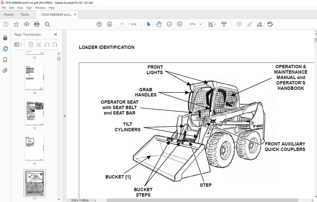
LOADER IDENTIFICATION 17
SAFETY AND MAINTENANCE 19
LIFTING AND BLOCKING THE LOADER 23
Procedure 23
LIFT ARM SUPPORT DEVICE 25
Description 25
Installing 26
Removing 27
OPERATOR CAB 29
Description 29
Raising 30
Lowering 31
Cab Door Sensor 32
Special Applications Kit 32
Special Applications Kit Inspection And Maintenance 32
Forestry Door And Window Kit 33
Forestry Door And Window Kit Inspection And Maintenance 33
TRANSPORTING THE LOADER ON A TRAILER 35
Loading And Unloading 35
Fastening 35
TOWING THE LOADER 37
Procedure 37
REMOTE START TOOL KIT – MEL1563 39
Remote Start Tool – MEL1563 39
Service Tool Harness Communicator – MEL1566 41
Remote Start Procedure 41
REMOTE START TOOL (SERVICE TOOL) KIT – 7217666 45
Description 45
Remote Start Tool (Service Tool) – 7022042 46
Loader Service Tool Harness – 6689747 47
Computer Service Tool Harness – 6689746 48
Remote Start Procedure 49
SERVICE SCHEDULE 53
Maintenance Intervals 53
ENGINE AIR CLEANER 55
Replacing Filters 55
ENGINE COOLING SYSTEM (EARLIER MODELS) 57
Maintenance Platform 57
Cooling System Identification 57
Cleaning 57
Checking And Adding Coolant 59
Removing And Replacing Coolant 60
ENGINE COOLING SYSTEM (LATER MODELS) 61
Maintenance Platform 61
Cleaning 61
Checking And Adding Coolant 63
Removing And Replacing Coolant 64
FUEL SYSTEM 65
Fuel Specifications 65
Biodiesel Blend Fuel 65
Filling The Fuel Tank 66
Fuel Filter 67
Removing Air From The Fuel System 68
ENGINE LUBRICATION SYSTEM 69
Checking And Adding Engine Oil 69
Engine Oil Chart 69
Removing And Replacing Oil And Filter 70
HYDRAULIC / HYDROSTATIC SYSTEM (EARLIER MODELS) 71
Checking And Adding Fluid 71
Hydraulic / Hydrostatic Fluid Chart 71
Removing And Replacing Hydraulic Fluid 72
Removing And Replacing Hydraulic / Hydrostatic Filter 74
Removing And Replacing Hydraulic Charge Filter 75
Replacing Reservoir Breather Cap 76
HYDRAULIC / HYDROSTATIC SYSTEM (LATER MODELS) 77
Checking And Adding Fluid 77
Hydraulic / Hydrostatic Fluid Chart 77
Removing And Replacing Hydraulic Fluid 78
Removing And Replacing Hydraulic / Hydrostatic Filter 80
Removing And Replacing Hydraulic Charge Filter 81
Replacing Reservoir Breather Cap 82
FINAL DRIVE TRANSMISSION (CHAINCASE) 83
Checking And Adding Fluid 83
Removing And Replacing Fluid 83
BOB-TACH (HAND LEVER) 85
Inspection And Maintenance 85
BOB-TACH (POWER) 87
Inspection And Maintenance 87
LUBRICATING THE LOADER 89
Lubrication Locations 89
TIRE MAINTENANCE 93
Wheel Nuts 93
Rotating 93
Mounting 94
SPARK ARRESTER MUFFLER 95
Cleaning Procedure 95
PIVOT PINS 97
Inspection And Maintenance 97
LOADER STORAGE AND RETURN TO SERVICE 99
Storage 99
Return To Service 99
STOPPING THE ENGINE AND LEAVING THE LOADER 101
Procedure 101
EMERGENCY EXIT 103
Rear Window Identification 103
Rear Window Removal (Latches) 103
Rear Window Removal (Rubber Cord) 103
External Access (Rear Window With Latches) 104
External Access (Rear Window With Rubber Cord) 104
Front Door 105
SEAT BELT 107
Inspection And Maintenance 107
HYDRAULIC SYSTEM 109
HYDRAULIC / HYDROSTATIC SCHEMATICS 115
HYDRAULIC SYSTEM INFORMATION 131
Glossary Of Hydraulic / Hydrostatic Symbols 131
Troubleshooting 135
CYLINDER (LIFT) 137
Testing 137
Removal And Installation 138
Parts Identification 141
Disassembly 142
Assembly 144
CYLINDER (TILT) 147
Testing 147
Removal And Installation 148
Base End Pivot Pin Removal And Installation 149
Parts Identification 150
Disassembly 151
Assembly 153
CYLINDER (LIFT) (AZN811740 & ABOVE) 157
Testing 157
Removal And Installation 158
Parts Identification 161
Disassembly 162
Assembly 164
CYLINDER (TILT) (AZN811740 & ABOVE) 169
Testing 169
Removal And Installation 170
Base End Pivot Pin Removal And Installation 171
Parts Identification 172
Disassembly 173
Assembly 175
CYLINDER (BOB-TACH) 179
Testing 179
Removal And Installation 180
Parts Identification 181
Disassembly 182
Assembly 184
MAIN RELIEF VALVE 187
Description 187
Testing 188
Adjusting 190
Removal And Installation 191
HYDRAULIC CONTROL VALVE (STANDARD) 193
Description 193
Removal And Installation 194
Mount Bracket Removal And Installation 197
Identification Chart 198
Lift Load Check Valve Removal And Installation 199
Load Check Valve Removal And Installation (Tilt And Auxiliary) 200
Anti-Cavitation Valve Removal And Installation (Lift, Rod End) 201
Port Relief / Anti-Cavitation Valve Removal And Installation (Lift, Base End) 201
Port Relief / Anti-Cavitation Valve Removal And Installation (Tilt, Base End) 202
Port Relief / Anti-Cavitation Valve Removal And Installation (Tilt, Rod End) 202
Port Relief Valve Removal And Installation 203
Plug Removal And Installation 205
Rubber Boot Removal And Installation 206
End Cap Block Removal And Installation 206
Lift Spool And Detent Removal And Installation 207
Tilt Spool Removal And Installation 215
Auxiliary Spool Removal And Installation 217
Auxiliary Solenoid Removal And Installation 218
Solenoid Removal And Installation 219
Lock Valve Removal And Installation 220
Lift Arm Bypass Orifice Removal And Installation 222
Main Relief Valve Removal And Installation 222
Check Valve Removal And Installation 223
HYDRAULIC CONTROL VALVE (ACS) OR (SJC) 225
Description 225
Removal And Installation 225
Actuator Removal And Installation (In Loader) 229
Actuator Removal And Installation (Out Of Loader) 231
Identification Chart 234
Mount Bracket Removal And Installation 235
Lift Load Check Valve Removal And Installation 235
Load Check Valve Removal And Installation (Tilt And Auxiliary) 236
Anti-Cavitation Valve Removal And Installation (Lift, Rod End) 237
Port Relief / Anti-Cavitation Valve Removal And Installation (Lift, Base End) 237
Port Relief / Anti-Cavitation Valve Removal And Installation (Tilt, Base End) 238
Port Relief / Anti-Cavitation Valve Removal And Installation (Tilt, Rod End) 238
Port Relief Valve Removal And Installation 239
Plug Removal And Installation 241
End Cap Block Removal And Installation 242
Lift Spool Removal And Installation 242
Lift Spool Disassembly And Assembly 244
Tilt Spool Removal And Installation 245
Auxiliary Spool Removal And Installation 247
Auxiliary Solenoid Removal And Installation 248
Solenoid Removal And Installation 249
Lock Valve Removal And Installation 250
Lift Arm Bypass Orifice Removal And Installation 252
Main Relief Valve Removal And Installation 252
Check Valve Removal And Installation 253
LIFT ARM BYPASS CONTROL VALVE 255
Description 255
Testing 255
Removal And Installation 256
Bracket Removal And Installation 257
Disassembly And Assembly 257
HYDRAULIC PUMP 259
Description 259
Pump Test At Quick Couplers 260
Direct Pump Test (Standard Section) 262
Direct Pump Test (Charge Section) 264
Removal And Installation 266
Hydraulic Pump Startup 268
Parts Identification 269
Disassembly And Assembly 270
HYDRAULIC PUMP (HIGH FLOW) 271
Description 271
Pump Test At Quick Couplers 272
Direct Pump Test (Standard Section) 274
Direct Pump Test (Charge Section) 275
Direct Pump Test (High Flow Section) 277
High Flow Relief Valve Adjustment 279
High Flow Relief Valve Removal And Installation 281
Solenoid Removal And Installation 282
Removal And Installation 283
Hydraulic Pump Startup 285
Parts Identification 286
Disassembly And Assembly 287
HYDRAULIC / HYDROSTATIC FILTERS 289
Description 289
Housing Removal And Installation 289
HYDRAULIC FLUID RESERVOIR 291
Description 291
Removal And Installation 291
Hydraulic Fluid Screen 292
OIL COOLER (EARLIER MODELS) 293
Description 293
Removal And Installation 293
OIL COOLER (LATER MODEL) 295
Removal And Installation 295
BUCKET POSITION VALVE 297
Description 297
Solenoid Removal And Installation 297
Solenoid Testing 298
Removal And Installation 299
Disassembly And Assembly 301
REAR AUXILIARY DIVERTER VALVE 303
Description 303
Solenoid Testing 303
Removal And Installation 304
Disassembly And Assembly 305
BOB-TACH (POWER) BLOCK (S/N A3NL11001 – A3NL12242) 311
Description 311
Removal And Installation 311
Disassembly And Assembly 313
BOB-TACH (POWER) BLOCK (S/N A3NL12243 & ABOVE) 321
Description 321
Testing Relief Valve 322
Removal And Installation 324
Disassembly And Assembly 326
FRONT AUXILIARY HYDRAULIC COUPLER BLOCK 331
Description 331
Removal And Installation 332
Disassembly And Assembly (FFI/FI) 332
Disassembly And Assembly (FFH/FH) 334
AUTOMATIC RIDE CONTROL 337
Description 337
Removal And Installation 338
Checking The Pressure In The Accumulator 341
Adding Nitrogen To The Accumulator 343
HYDROSTATIC SYSTEM 345
HYDROSTATIC SYSTEM INFORMATION 347
Description 347
Troubleshooting 348
HYDROSTATIC DRIVE MOTOR 349
Description 349
Removal And Installation 349
Parts Identification 352
Disassembly And Assembly 353
HYDROSTATIC DRIVE MOTOR (TWO-SPEED) 359
Description 359
Removal And Installation (Left Side) 360
Removal And Installation (Right Side) 363
Parts Identification 366
Disassembly 367
Assembly 380
HYDROSTATIC MOTOR CARRIER 395
Description 395
Shaft Seal Removal And Installation 396
Removal And Installation 398
Parts Identification 400
Disassembly 401
Assembly 403
HYDROSTATIC MOTOR CARRIER (TWO-SPEED) 407
Description 407
Shaft Seal Removal And Installation 408
Removal And Installation 410
Parts Identification 412
Disassembly 413
Assembly 415
CHARGE PRESSURE 419
Description 419
Testing 420
Adjusting 422
Sender Removal And Installation 424
HYDROSTATIC PUMP 425
Description 425
Removal And Installation 426
Hydrostatic Pump Startup 427
Replenishing / High Pressure Relief Valve Removal And Installation 428
Parts Identification (Left Half) 429
Parts Identification (Right Half) 430
Disassembly 431
Assembly 438
HYDROSTATIC PUMP (SJC) 445
Description 445
Hydraulic Controller Removal And Installation 446
Removal And Installation 448
Hydrostatic Pump Startup 450
Parts Identification 451
High Pressure Relief And Bypass Valve 452
Charge Relief Valve 453
Disassembly And Assembly 454
Mechanical Neutral Adjustment 467
Hydraulic Controller Neutral Adjustment 470
HYDROSTATIC PUMP (SJC) (S/N A3NL13651 & ABOVE) 473
Description 473
Port Locations And Gauge Installation 474
Removal And Installation 475
Hydrostatic Pump Startup 477
Parts Identification 478
High Pressure Relief And Bypass Valve 481
Charge Pressure Relief Valve 482
Disassembly And Assembly 483
Mechanical Neutral Adjustment 495
Hydraulic Controller Neutral Adjustment 497
DRIVE BELT 499
Belt Adjustment 499
Belt Replacement 500
TWO-SPEED 503
Valve Block Removal And Installation 503
Valve Block Disassembly And Assembly 504
DRAIN MANIFOLD 505
Description 505
Drain Manifold Removal And Installation 505
DRIVE SYSTEM 507
BRAKE 509
Description 509
Disc Removal And Installation 509
DRIVE COMPONENTS 511
Description 511
Axle Seal Removal And Installation 512
Axle, Sprocket And Bearings Removal And Installation 514
Chain Removal And Installation 519
CHAINCASE 521
Description 521
Front Cover Removal And Installation 521
Center Cover Removal And Installation 522
Rear Cover Removal And Installation 523
MAINFRAME 525
SEAT BAR 529
Description 529
Removal And Installation 529
Disassembly And Assembly 530
Compression Spring Disassembly And Assembly 531
OPERATOR CAB 533
Gas Spring Removal And Installation 533
Gas Spring Bracket Disassembly And Assembly 534
Removal And Installation 535
OPERATOR SEAT 537
Removal And Installation 537
Seat Belt Removal And Installation (Retractable) 537
Seat Belt And Bracket Removal And Installation (Standard) 538
Seat Belt Bracket Removal And Installation 538
OPERATOR SEAT (SUSPENSION) 539
Removal And Installation 539
Slide Rail Removal And Installation 539
Seat Belt Removal And Installation 540
Lower Cushion Removal 540
Lower Cushion Installation 541
Back Cushion Removal And Installation 541
Shock Removal And Installation 542
3-Point Seat Belt Removal And Installation 542
BOB-TACH (HAND LEVER) 545
Description 545
Removal And Installation 545
Lever And Wedge Disassembly And Assembly 547
Pivot Pin Bushing And Seal Removal And Installation 549
BOB-TACH (POWER) 551
Description 551
Removal And Installation 551
Lever And Wedge Disassembly And Assembly 554
Pivot Pin Bushing And Seal Removal And Installation 556
LIFT ARMS 557
Removal And Installation 557
REAR GRILLE 559
Removing 559
Installing 559
REAR DOOR (TAILGATE) 561
Removal And Installation 561
Striker Removal And Installation 562
Striker Disassembly And Assembly 562
Striker Adjusting 563
Latch Removal And Installation 563
FUEL TANK 565
Removal And Installation 565
Fuel Level Sender Removal And Installation 568
Fuel Fill Screen Removal And Installation 568
CONTROL PEDALS AND LINKAGES 569
Description 569
Pedal Removal And Installation 569
Linkage Removal And Installation 570
Pedal (Adjusting) 571
Floor Pan Removal And Installation 572
CONTROL PEDALS AND LINKAGES (ACS) 573
Description 573
Pedal Removal And Installation 573
Linkage Removal And Installation 574
Pedal (Adjusting) 574
Floor Pan Removal And Installation 575
CONTROL PANEL 577
Description 577
Removal And Installation 578
Disassembly And Assembly 579
Linkage Removal And Installation 584
Pintle Arm Disassembly And Assembly 587
Linkage Neutral (Adjusting) 588
Linkage Travel (Adjusting) 592
Shock Removal And Installation 596
CONTROL PANEL (SJC) 597
Description 597
Removal And Installation 597
CONTROL HANDLE / LEVER 599
Description 599
Lever Removal And Installation 599
Boot Removal And Installation 599
CONTROL HANDLE / LEVER (ACS) 601
Description 601
Handle Sensor Removal And Installation 601
Handle Removal And Installation 604
Handle Disassembly And Assembly 605
Lever Removal And Installation 605
Boot Removal And Installation 606
CONTROL HANDLE / LEVER (SJC) 607
Description 607
Joystick Testing 607
Joystick Removal And Installation 608
ACCESS PANEL (INSIDE) 609
Removal And Installation (Left) 609
Removal And Installation (Right) 609
ACCESS PANEL (INSIDE) (SJC) 611
Removal And Installation (Left) 611
Removal And Installation (Right) 612
WINDOW (REAR) 613
Rear Window Identification 613
Rear Window Removal (Latches) 613
Rear Window Removal (Rubber Cord) 613
Disassembly And Assembly 614
External Access (Rear Window With Latches) 615
External Access (Rear Window With Rubber Cord) 615
WINDOW (TOP) 617
Removal And Installation 617
WINDOW (SIDE) 619
Removal And Installation 619
CAB DOOR 621
Description 621
Removal And Installation 621
Disassembly And Assembly 622
Aligning 623
Adjusting 624
Checking Operation 624
ARMREST 625
Description 625
Removal And Installation 625
Disassembly And Assembly 626
LEFT SIDE LOWER PANEL 629
Removal And Installation 629
Disassembly And Assembly 632
RIGHT SIDE LOWER PANEL 633
Removal And Installation 633
Disassembly And Assembly 635
HEADLINER 637
Removal And Installation 637
ELECTRICAL SYSTEM 639
ELECTRICAL SCHEMATICS 645
ELECTRICAL SYSTEM INFORMATION 823
Glossary Of Electrical Symbols 823
Standard Cab Harness Connectors 826
Deluxe Cab Harness Connectors 827
Mainframe Harness Connectors – Manual Controls 828
Mainframe Harness Connectors – SJC 829
Description 830
Troubleshooting 831
Fuse And Relay Location / Identification 832
BATTERY 837
Removal And Installation 837
Battery Maintenance 838
Maintaining Battery Charge Level 838
Battery Service During Machine Storage 838
Battery Testing 839
Battery Charging 839
Using A Booster Battery (Jump Starting) 840
ALTERNATOR 841
Belt Adjustment 841
Belt Replacement 841
Charging System Inspection 842
Alternator Voltage Testing 843
Low Voltage Testing 843
High Voltage Testing 844
Removal And Installation 845
Parts Identification 847
STARTER 849
Testing 849
Removal And Installation 849
Parts Identification 850
INSTRUMENT PANELS 851
Left Panel 851
Display Screen 853
Right Panel (Standard Key Panel) 854
Right Panel (Keyless Start Panel) 855
Right Panel (Deluxe Instrumentation Panel) 856
Left Switch Panel 858
Right Switch Panel 858
Left Side Lower Panel 859
Right Side Lower Panel 859
Left Panel Removal And Installation 860
Right Panel (Standard Key Panel) Removal And Installation 860
Right Panel (Keyless Start Panel) Removal And Installation 861
Right Panel (Deluxe Instrumentation Panel) Removal And Installation 861
Key Switch Disassembly And Assembly 862
Alarm Disassembly And Assembly 862
Left Switch Panel Removal And Installation 863
Right Switch Panel Removal And Installation 863
LIGHTS 865
Front Removal And Installation 865
Rear Removal And Installation 866
Cab Light Removal And Installation 866
BOBCAT CONTROLLERS (GATEWAY AND AUXILIARY) 867
Description 867
Connector Identification 868
Removal And Installation 874
BOBCAT CONTROLLER (ACS) 875
Description 875
Connector And Wire Identification 876
Removal And Installation 877
BOBCAT CONTROLLER (SJC) (DRIVE) 879
Description 879
Connector Identification 880
Removal And Installation 882
DIAGNOSTIC SERVICE CODES 883
Viewing Service Codes 883
Service Codes List 884
BOBCAT INTERLOCK CONTROL SYSTEM (BICS™) 891
Description 891
Inspecting The BICS™ (Engine STOPPED – Key ON) 892
Inspecting Deactivation Of The Auxiliary Hydraulics System (Engine STOPPED – Key ON) 892
Inspecting The Seat Bar Sensor (Engine RUNNING) 892
Inspecting The Traction Lock And Parking Brake (Engine RUNNING) 892
Inspecting The Lift Arm Bypass Control 892
Inspecting Deactivation Of Lift And Tilt Functions (ACS And SJC) 892
Troubleshooting 893
SEAT BAR SENSOR 895
Description 895
Troubleshooting 895
Testing 896
Removal 897
Installation 899
Bobcat Interlock Control System (BICS™) Circuit Test 900
TRACTION LOCK 903
Description 903
Troubleshooting 904
Inspecting 905
CONTROL SYSTEM (ACS) 907
Description 907
Troubleshooting 908
Handle Sensor Connector Disassembly And Assembly 909
Switch Handle Removal 910
Switch Handle Installation 913
Actuator Connector Disassembly And Assembly 916
Handle Lock Solenoid Removal And Installation 917
Handle Lock Solenoid Disassembly And Assembly 917
Foot Sensor Removal And Installation 918
Foot Sensor Disassembly And Assembly 919
Foot Sensor Lock Solenoid Removal And Installation 919
ELECTRICAL / HYDRAULIC CONTROLS 921
Identification Chart 921
Description 922
Identification Chart ACD Group 0 923
Identification Chart ACD Group 1 924
Identification Chart ACD Group 2 925
Identification Chart ACD Group 3 926
ELECTRICAL / HYDRAULIC CONTROLS (ACS) 927
Identification Chart 927
Description 928
Identification Chart ACD Group 0 929
Identification Chart ACD Group 1 930
Identification Chart ACD Group 2 931
Identification Chart ACD Group 3 932
ELECTRICAL / HYDRAULIC CONTROLS (SJC) 933
Identification Chart 933
Description 934
Identification Chart ACD Group 0 935
Identification Chart ACD Group 1 936
Identification Chart ACD Group 2 937
Identification Chart ACD Group 3 938
SERVICE PC (LAPTOP COMPUTER) 939
Connecting Remote Start Tool 939
Connecting Remote Start Tool (Service Tool) 939
CALIBRATION 941
Description 941
Actuator Testing 941
Lift And Tilt Calibration (SJC) 944
Hydrostatic Pump Calibration (SJC) 946
Lift And Tilt Calibration (ACS) 951
STEERING DRIFT COMPENSATION (OPERATOR MODE) 953
Description 953
Operation 953
STEERING DRIFT COMPENSATION (SERVICE MODE) 955
Description 955
Operation 955
FLYWHEEL RPM SENSOR 957
Description 957
Removal 957
Installation 958
CONTROL PANEL SETUP 959
Right Panel Setup (Deluxe Instrumentation Panel) 959
PASSWORD SETUP (DELUXE INSTRUMENTATION PANEL) 963
Password Description 963
Changing The Owner Password 963
Changing The User Passwords 964
Password Lockout Feature 964
PASSWORD SETUP (KEYLESS START PANEL) 965
Password Description 965
Changing The Owner Password 965
Password Lockout Feature 965
MAINTENANCE CLOCK 967
Description 967
Setup 968
Reset 971
BACK-UP ALARM SYSTEM 973
Description 973
Inspection 973
Adjusting Switch Position 974
Troubleshooting (Standard And ACS) 975
Troubleshooting (Joystick) 976
Alarm Removal And Installation 977
Switch Removal And Installation 977
FRONT HORN 979
Removal And Installation 979
Troubleshooting 980
Troubleshooting (Joystick) 981
TELEMATICS 983
Description 983
Removal And Installation 983
Procedure 984
ENGINE SERVICE 985
ENGINE INFORMATION 989
Description 989
Specifications 990
Torque Values 993
Troubleshooting 993
Engine Removal And Installation 995
Engine Mount Replacement 1004
Compression – Testing 1005
ENGINE SPEED CONTROL (HAND) 1007
Removal And Installation 1007
Disassembly And Assembly 1007
Cable Removal And Installation 1008
ENGINE SPEED CONTROL (FOOT) 1009
Removal And Installation 1009
Disassembly And Assembly 1010
MUFFLER 1013
Removal And Installation 1013
AIR CLEANER 1015
Housing Removal And Installation 1015
ENGINE COOLING SYSTEM (EARLIER MODELS) 1017
Radiator Removal And Installation 1017
Hydraulic Fan Description 1019
Fan Duct Removal And Installation 1019
Hydraulic Fan Motor Assembly Removal And Installation 1020
Hydraulic Fan Motor Removal And Installation 1021
Hydraulic Fan Motor Disassembly And Assembly 1023
Blower Housing Removal And Installation 1024
Water Pump Removal And Installation 1025
Water Pump Disassembly And Assembly 1025
Thermostat Housing Removal And Installation 1026
Thermostat – Testing 1027
ENGINE COOLING SYSTEM (LATER MODELS) 1029
Radiator / Oil Cooler Removal And Installation 1029
Hydraulic Fan Description 1032
Reversible Hydraulic Fan Description 1032
Fan Duct Removal And Installation 1032
Hydraulic Fan Motor Assembly Removal And Installation 1033
Hydraulic Fan Motor Removal And Installation 1034
Hydraulic Fan Motor Disassembly And Assembly 1036
Blower Housing Removal And Installation 1044
Water Pump Removal And Installation 1045
Water Pump Disassembly And Assembly 1045
Thermostat Housing Removal And Installation 1046
Thermostat – Testing 1047
LUBRICATION SYSTEM 1049
Oil Pan Removal And Installation 1049
Oil Pump Removal And Installation 1049
Relief Valve – Testing 1050
Oil Pump Inspection 1050
Oil Filter Cooler Removal And Installation 1052
Engine Oil Pressure – Testing 1052
FUEL SYSTEM 1053
Fuel Shutoff Solenoid – Testing 1053
Fuel Shutoff Solenoid Removal And Installation 1053
Fuel Injection Pump – Testing 1054
Fuel Injection Pump Assembly Removal And Installation 1055
Governor Housing Disassembly And Assembly 1058
Governor Disassembly And Assembly 1060
Fuel Camshaft Removal And Installation 1062
Fuel Injection Pump Removal And Installation 1065
Fuel Injection Pump – Timing 1067
Fuel Injector Removal And Installation 1069
Fuel Injector Nozzle Pressure – Testing 1070
Nozzle Spray Condition 1071
Valve Seat Tightness 1071
CYLINDER HEAD 1073
Glow Plugs – Testing 1073
Glow Plugs Removal And Installation 1073
Valve Clearance Adjustment 1074
Valve Timing – Inspecting 1075
Cylinder Head Removal And Installation 1076
Cylinder Head Disassembly And Assembly 1079
Cylinder Head – Servicing 1080
Cylinder Head Top Clearance 1081
Valve Guide – Inspecting 1082
Valve Guide Removal And Installation 1082
Reconditioning The Valve And Valve Seat 1083
Valve Spring 1085
Valve Tappets 1086
Rocker Arm And Shaft – Inspecting 1087
Bridge Arm And Bridge Arm Shaft – Inspecting 1087
Bridge Arm Shaft – Removal And Installation 1088
Push Rod Alignment – Inspecting 1089
CRANKSHAFT AND PISTONS 1091
Piston And Connecting Rod Removal And Installation 1091
Piston And Connecting Rod – Servicing 1092
Cylinder Bore – Inspecting 1096
Connecting Rod Alignment 1096
Crankshaft Gear Removal And Installation 1097
Crankshaft And Bearings Removal And Installation 1098
Crankshaft And Bearings – Servicing 1101
CAMSHAFT AND TIMING GEARS 1105
Timing Gearcase Cover Removal 1105
Timing Gearcase Cover Installation 1106
Timing Gears Backlash – Inspection 1109
Idler Gear And Camshaft Removal And Installation 1109
Camshaft – Servicing 1110
Idler Gear And Shaft – Servicing 1111
TURBOCHARGER 1113
Description 1113
Testing 1113
Removal And Installation 1114
FLYWHEEL AND HOUSING 1115
Flywheel Removal And Installation 1115
Ring Gear Removal And Installation 1116
Housing Removal And Installation 1117
EXHAUST GAS RECIRCULATION (EGR) SYSTEM 1119
Description 1119
Testing 1120
Removal And Installation 1123
Disassembly And Assembly 1124
HEATING, VENTILATION AND AIR CONDITIONING (HVAC) 1125
AIR CONDITIONING SYSTEM FLOW 1127
Description 1127
Chart 1128
Components 1129
Safety Equipment 1132
REGULAR MAINTENANCE 1133
Filters 1133
Belt Adjustment 1134
Belt Replacement 1134
Air Conditioning Condenser 1134
Air Conditioning Lubrication 1134
Air Conditioning Service Chart 1135
Evaporator / Heater Coil 1136
TROUBLESHOOTING 1139
Blower Motor Does Not Operate 1139
Blower Motor Operates Normally, But Air Flow Is Insufficient 1139
Insufficient Cooling Although Air Flow And Compressor Operation Are Normal 1139
The Compressor Does Not Operate At All, Or Operates Improperly 1139
Gauge Pressure Related Troubleshooting 1140
Troubleshooting Tree 1142
Temperature / Pressure Chart 1146
Poor A/C Performance 1148
HVAC Repair And Leaks 1149
Electrical System 1150
Engine Coolant Bypassing The Heater Valve 1156
Heater Valve Not Opening Or Closing 1157
SYSTEM CHARGING AND RECLAMATION 1159
Refrigerant Identification 1159
Reclamation And Charging With Recovery / Charging Unit 1160
COMPRESSOR 1163
Removal And Installation 1163
Oil 1164
Oil Check 1165
CONDENSER (EARLIER MODELS) 1167
Removal And Installation 1167
CONDENSER (LATER MODELS) 1169
Removal And Installation 1169
RECEIVER / DRIER (EARLIER MODELS) 1171
Receiver / Drier Removal And Installation 1171
Pressure Relief Valve Removal And Installation 1172
Pressure Switch Removal And Installation 1173
Schrader® Valve Removal And Installation 1174
RECEIVER / DRIER (LATER MODELS) 1175
Receiver / Drier Removal And Installation 1175
Pressure Switch Removal And Installation 1177
Schrader® Valve Removal And Installation 1178
EVAPORATOR / HEATER UNIT 1179
Removal And Installation 1179
THERMOSTAT 1181
Description 1181
Removal And Installation 1182
EXPANSION VALVE 1183
Removal And Installation 1183
EVAPORATOR COIL 1185
Removal And Installation 1185
HEATER COIL 1187
Removal And Installation 1187
BLOWER FAN 1189
Removal And Installation 1189
Disassembly And Assembly 1190
HEATER VALVE 1193
Removal And Installation 1193
EVAPORATOR / HEATER COVER 1195
Removing 1195
Installing 1195
SPECIFICATIONS 1197
(S550) LOADER SPECIFICATIONS 1199
Machine Dimensions 1199
Performance 1200
Engine 1200
Drive System 1201
Controls 1201
Hydraulic System 1202
Electrical System 1203
Capacities 1203
Tires 1204
TECHINCAL SERVICE GUIDE SPECIFICATIONS 1205
Engine 1205
Engine Torques 1205
Cooling System 1205
Loader Torques 1206
Hydraulic / Hydrostatic System 1206
Fuel Consumption 1206
TORQUE SPECIFICATIONS FOR BOLTS 1207
Torque For General SAE Bolts 1207
Torque For General Metric Bolts 1208
HYDRAULIC CONNECTION SPECIFICATIONS 1209
Straight Thread O-ring Fitting 1209
Flare Fitting 1210
Tubelines And Hoses 1210
HYDRAULIC / HYDROSTATIC FLUID SPECIFICATIONS 1211
Specifications 1211
CONVERSIONS 1213
Decimal And Millimeter Equivalent Chart 1213
U S To Metric Conversion Chart 1213
SERVICE TOOLS REQUIRED 1215
Remote Start Tools 1215
Hydraulic Tools 1216
Mainframe And Drive Tools 1219
Electrical Tools 1222
Engine Tools 1223
HVAC Tools 1228
ALPHABETICAL INDEX 1229
IMAGES PREVIEW OF THE MANUAL:
Contact us: [email protected]
https://vimeo.com/843839827?share=copy
PLEASE NOTE:
- This is the SAME MANUAL used by the dealerships to diagnose your vehicle
- No waiting for couriers / posts as this is a PDF manual and you can download it within 2 minutes time once you make the payment.
- Your payment is all safe and the delivery of the manual is INSTANT – You will be taken to the DOWNLOAD PAGE.
- So have no hesitations whatsoever and write to us about any queries you may have : heydownloadss @gmail.com
S.V