Bobcat S550 Skid-Steer Loader Service Manual 6990677 – PDF DOWNLOAD
$36.95
Bobcat S550 Skid-Steer Loader Service Manual 6990677 – PDF DOWNLOAD
Description
Bobcat S550 Skid-Steer Loader Service Manual 6990677 – PDF DOWNLOAD
FILE DETAILS:
Bobcat S550 Skid-Steer Loader Service Manual 6990677 – PDF DOWNLOAD
Language : English
Pages : 1310
Downloadable : Yes
File Type : PDF
DESCRIPTION:
Bobcat S550 Skid-Steer Loader Service Manual 6990677 – PDF DOWNLOAD
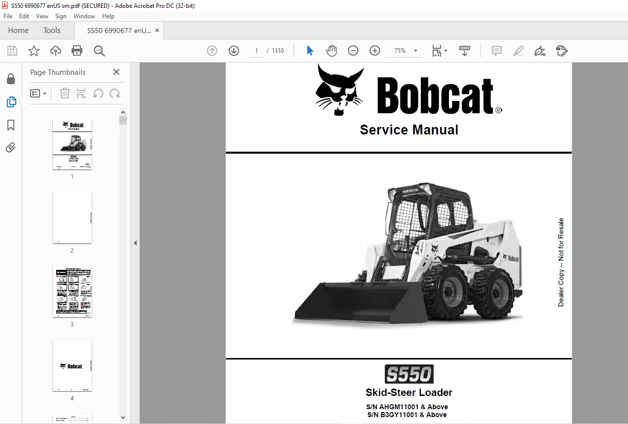
S/N AHGM11001 & Above
S/N B3GY11001 & Above
FOREWORD:
This manual is for the Bobcat loader mechanic. It provides necessary servicing and adjustment procedures for the Bobcat loader and its component parts and systems. Refer to the Operation & Maintenance Manual for operating instructions, starting procedure, daily checks, etc.
A general inspection of the following items must be made after the loader has had service or repair:
TABLE OF CONTENTS:
Bobcat S550 Skid-Steer Loader Service Manual 6990677 – PDF DOWNLOAD
MAINTENANCE SAFETY 3
CONTENTS 5
FOREWORD 7
FOREWORD 9
SAFETY INSTRUCTIONS 11
FIRE PREVENTION 13
Maintenance 13
Operation 13
Electrical 13
Hydraulic System 13
Fueling 13
Starting 13
Spark Arrester Exhaust System 13
Welding And Grinding 14
Fire Extinguishers 14
SERIAL NUMBER LOCATIONS 15
Loader Serial Number 15
Engine Serial Number 15
DELIVERY REPORT 16
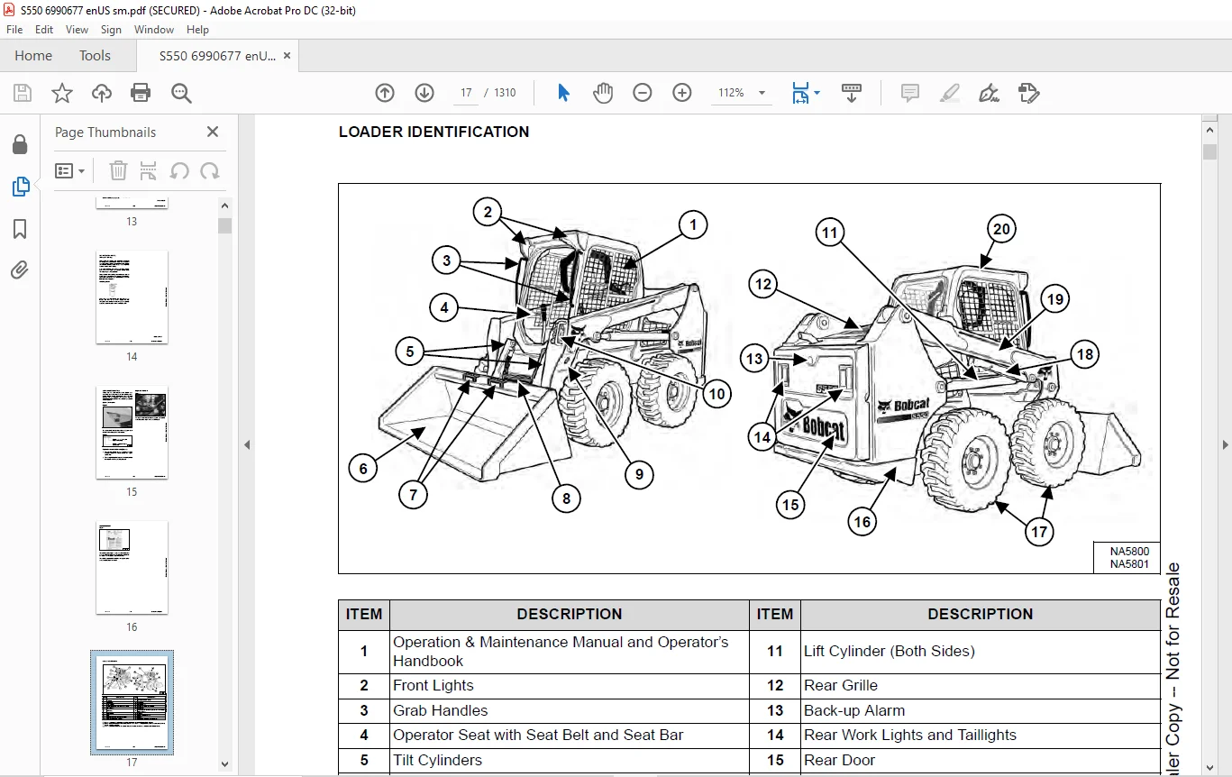
LOADER IDENTIFICATION 17
SAFETY AND MAINTENANCE 19
LIFTING AND BLOCKING THE LOADER 23
Procedure 23
LIFT ARM SUPPORT DEVICE 25
Description 25
Installing 26
Removing 27
OPERATOR CAB 29
Description 29
Cab Door Sensor 29
Raising 30
Lowering 31
Special Applications Kit 32
Special Applications Kit Inspection And Maintenance 32
Forestry Door And Window Kit 33
Forestry Door And Window Kit Inspection And Maintenance 33
TRANSPORTING THE LOADER ON A TRAILER 35
Loading And Unloading 35
Fastening 35
TOWING THE LOADER 37
Procedure 37
REMOTE START TOOL KIT – MEL1563 39
Remote Start Tool – MEL1563 39
Service Tool Harness Communicator – MEL1566 41
Remote Start Procedure 41
REMOTE START TOOL (SERVICE TOOL) KIT – 7217666 45
Description 45
Remote Start Tool (Service Tool) – 7022042 46
Loader Service Tool Harness – 6689747 47
Computer Service Tool Harness – 6689746 48
Remote Start Procedure 49
SERVICE SCHEDULE 53
Maintenance Intervals 53
ENGINE AIR CLEANER 55
Replacing Filters 55
ENGINE COOLING SYSTEM 57
Maintenance Platform 57
Cleaning 57
Checking And Adding Coolant 60
Removing And Replacing Coolant 61
FUEL SYSTEM 63
Fuel Specifications 63
Biodiesel Blend Fuel 63
Filling The Fuel Tank 64
Fuel Filter 65
Removing Air From The Fuel System 67
ENGINE LUBRICATION SYSTEM 69
Checking And Adding Engine Oil 69
Engine Oil Chart 69
Removing And Replacing Oil And Filter 70
HYDRAULIC / HYDROSTATIC SYSTEM 73
Checking And Adding Fluid 73
Hydraulic / Hydrostatic Fluid Chart 73
Removing And Replacing Hydraulic Fluid 74
Removing And Replacing Hydraulic / Hydrostatic Filter 76
Removing And Replacing Hydraulic Charge Filter 77
Replacing Reservoir Breather Cap 79
FINAL DRIVE TRANSMISSION (CHAINCASE) 81
Checking And Adding Fluid 81
Removing And Replacing Fluid 81
BOB-TACH (HAND LEVER) 83
Inspection And Maintenance 83
BOB-TACH (POWER) 85
Inspection And Maintenance 85
LUBRICATING THE LOADER 87
Lubrication Locations 87
TIRE MAINTENANCE 91
Wheel Nuts 91
Rotating 91
Mounting 92
PIVOT PINS 93
Inspection And Maintenance 93
LOADER STORAGE AND RETURN TO SERVICE 95
Storage 95
Return To Service 95
STOPPING THE ENGINE AND LEAVING THE LOADER 97
Procedure 97
EMERGENCY EXIT 99
Rear Window Identification 99
Rear Window Removal (Latches) 99
Rear Window Removal (Rubber Cord) 99
External Access (Rear Window With Latches) 100
External Access (Rear Window With Rubber Cord) 100
Front Door 100
SEAT BELT 103
Inspection And Maintenance 103
HYDRAULIC SYSTEM 105
HYDRAULIC / HYDROSTATIC SCHEMATICS 111
HYDRAULIC SYSTEM INFORMATION 127
Glossary Of Hydraulic / Hydrostatic Symbols 127
Troubleshooting 131
CYLINDER (LIFT) 133
Testing 133
Removal And Installation 134
Parts Identification 137
Disassembly 138
Assembly 140
CYLINDER (TILT) 143
Testing 143
Removal And Installation 144
Base End Pivot Pin Removal And Installation 145
Parts Identification 146
Disassembly 147
Assembly 149
CYLINDER (LIFT) (B3GY11244 & ABOVE) 153
Testing 153
Removal And Installation 154
Parts Identification 157
Disassembly 158
Assembly 160
CYLINDER (TILT) (B3GY11244 & ABOVE) 165
Testing 165
Removal And Installation 166
Base End Pivot Pin Removal And Installation 167
Parts Identification 168
Disassembly 169
Assembly 171
CYLINDER (BOB-TACH) 175
Testing 175
Removal And Installation 176
Parts Identification 177
Disassembly 178
Assembly 179
MAIN RELIEF VALVE 183
Description 183
Testing 184
Adjusting 186
Removal And Installation 187
HYDRAULIC CONTROL VALVE (STANDARD) 189
Description 189
Removal And Installation 190
Mount Bracket Removal And Installation 193
Identification Chart 194
Lift Load Check Valve Removal And Installation 195
Load Check Valve Removal And Installation (Tilt And Auxiliary) 196
Anti-Cavitation Valve Removal And Installation (Lift, Rod End) 197
Port Relief / Anti-Cavitation Valve Removal And Installation (Lift, Base End) 197
Port Relief / Anti-Cavitation Valve Removal And Installation (Tilt, Base End) 198
Port Relief / Anti-Cavitation Valve Removal And Installation (Tilt, Rod End) 198
Port Relief Valve Removal And Installation 199
Plug Removal And Installation 201
Rubber Boot Removal And Installation 202
End Cap Block Removal And Installation 202
Lift Spool And Detent Removal And Installation 203
Tilt Spool Removal And Installation 211
Auxiliary Spool Removal And Installation 213
Auxiliary Solenoid Removal And Installation 214
Solenoid Removal And Installation 215
Lock Valve Removal And Installation 216
Lift Arm Bypass Orifice Removal And Installation 218
Main Relief Valve Removal And Installation 218
Check Valve Removal And Installation 219
HYDRAULIC CONTROL VALVE (ACS) OR (SJC) 221
Description 221
Removal And Installation 221
Actuator Removal And Installation (In Loader) 225
Actuator Removal And Installation (Out Of Loader) 226
Identification Chart 229
Mount Bracket Removal And Installation 230
Lift Load Check Valve Removal And Installation 230
Load Check Valve Removal And Installation (Tilt And Auxiliary) 231
Anti-Cavitation Valve Removal And Installation (Lift, Rod End) 232
Port Relief / Anti-Cavitation Valve Removal And Installation (Lift, Base End) 232
Port Relief / Anti-Cavitation Valve Removal And Installation (Tilt, Base End) 233
Port Relief / Anti-Cavitation Valve Removal And Installation (Tilt, Rod End) 233
Port Relief Valve Removal And Installation 234
Plug Removal And Installation 236
End Cap Block Removal And Installation 237
Lift Spool Removal And Installation 237
Lift Spool Disassembly And Assembly 239
Tilt Spool Removal And Installation 240
Auxiliary Spool Removal And Installation 242
Auxiliary Solenoid Removal And Installation 243
Solenoid Removal And Installation 244
Lock Valve Removal And Installation 245
Lift Arm Bypass Orifice Removal And Installation 247
Main Relief Valve Removal And Installation 247
Check Valve Removal And Installation 248
LIFT ARM BYPASS CONTROL VALVE 249
Description 249
Testing 249
Removal And Installation 250
Bracket Removal And Installation 251
Disassembly And Assembly 251
HYDRAULIC PUMP 253
Description 253
Pump Test At Quick Couplers 254
Direct Pump Test (Standard Section) 256
Direct Pump Test (Charge Section) 258
Removal And Installation 260
Hydraulic Pump Startup 262
Parts Identification 263
Disassembly And Assembly 264
HYDRAULIC PUMP (HIGH FLOW) 265
Description 265
Pump Test At Quick Couplers 266
Direct Pump Test (Standard Section) 268
Direct Pump Test (Charge Section) 270
Direct Pump Test (High Flow Section) 272
High Flow Relief Valve Adjustment 274
High Flow Relief Valve Removal And Installation 276
Solenoid Removal And Installation 277
Removal And Installation 278
Hydraulic Pump Startup 280
Parts Identification 281
Disassembly And Assembly 282
HYDRAULIC / HYDROSTATIC FILTERS 283
Description 283
Housing Removal And Installation 283
HYDRAULIC FLUID RESERVOIR 285
Description 285
Removal And Installation 285
Hydraulic Fluid Screen 286
OIL COOLER 287
Removal And Installation 287
BUCKET POSITION VALVE 289
Description 289
Solenoid Removal And Installation 290
Solenoid Testing 292
Removal And Installation 292
Disassembly And Assembly 294
REAR AUXILIARY DIVERTER VALVE 295
Description 295
Solenoid Testing 295
Removal And Installation 296
Disassembly And Assembly 297
BOB-TACH (POWER) BLOCK (S/N AHGM11001 – AHGM11756) 303
Description 303
Removal And Installation 303
Disassembly And Assembly 305
BOB-TACH (POWER) BLOCK (S/N AHGM11757 & ABOVE) 313
Description 313
Testing Relief Valve 314
Removal And Installation 316
Disassembly And Assembly 318
FRONT AUXILIARY HYDRAULIC COUPLER BLOCK 323
Description 323
Removal And Installation 324
Disassembly And Assembly (FFI/FI) 324
Disassembly And Assembly (FFH/FH) 326
AUTOMATIC RIDE CONTROL 329
Description 329
Removal And Installation 330
Checking The Pressure In The Accumulator 333
Adding Nitrogen To The Accumulator 335
HYDROSTATIC SYSTEM 337
HYDROSTATIC SYSTEM INFORMATION 339
Description 339
Troubleshooting 340
HYDROSTATIC DRIVE MOTOR 341
Description 341
Removal And Installation 341
Parts Identification 344
Disassembly And Assembly 345
HYDROSTATIC DRIVE MOTOR (TWO-SPEED) 349
Description 349
Removal And Installation (Left Side) 350
Removal And Installation (Right Side) 353
Parts Identification 356
Disassembly 357
Assembly 369
HYDROSTATIC MOTOR CARRIER 383
Description 383
Shaft Seal Removal And Installation 384
Removal And Installation 386
Parts Identification 388
Disassembly 389
Assembly 391
HYDROSTATIC MOTOR CARRIER (TWO-SPEED) 395
Description 395
Shaft Seal Removal And Installation 396
Removal And Installation 398
Parts Identification 400
Disassembly 401
Assembly 403
CHARGE PRESSURE 407
Description 407
Testing 408
Adjusting 410
Sender Removal And Installation (Earlier Models) 412
Sender Removal And Installation (Later Models) 412
HYDROSTATIC PUMP 413
Description 413
Removal And Installation 414
Hydrostatic Pump Startup 415
Replenishing / High Pressure Relief Valve Removal And Installation 416
Parts Identification (Left Half) 417
Parts Identification (Right Half) 418
Disassembly 419
Assembly 426
HYDROSTATIC PUMP (SJC) 433
Description 433
Hydraulic Controller Removal And Installation 434
Removal And Installation 436
Hydrostatic Pump Startup 438
Parts Identification 439
High Pressure Relief And Bypass Valve 440
Charge Relief Valve 441
Disassembly And Assembly 442
Mechanical Neutral Adjustment 455
Hydraulic Controller Neutral Adjustment 459
HYDROSTATIC PUMP (SJC) (S/N AHGM18001 & ABOVE) 463
Description 463
Port Locations And Gauge Installation 464
Removal And Installation 465
Hydrostatic Pump Startup 467
Parts Identification 468
High Pressure Relief And Bypass Valve 471
Charge Pressure Relief Valve 472
Disassembly And Assembly 473
Mechanical Neutral Adjustment 485
Hydraulic Controller Neutral Adjustment 487
DRIVE BELT 489
Belt Adjustment 489
Stop Adjustment 489
Belt Replacement 490
Tensioner Removal And Installation (Earlier Models) 492
Tensioner Disassembly And Assembly 492
Tensioner Pulley Removal And Installation (Later Models) 493
Tensioner Pulley Disassembly And Assembly 493
TWO-SPEED 495
Valve Block Removal And Installation 495
Valve Block Disassembly And Assembly 496
DRAIN MANIFOLD 497
Description 497
Drain Manifold Removal And Installation 497
DRIVE SYSTEM 499
BRAKE 501
Description 501
Disc Removal And Installation 501
DRIVE COMPONENTS 503
Description 503
Axle Seal Removal And Installation 504
Axle, Sprocket And Bearings Removal And Installation 506
Chain Removal And Installation 511
CHAINCASE 513
Description 513
Front Cover Removal And Installation 513
Center Cover Removal And Installation 514
Rear Cover Removal And Installation 515
MAINFRAME 517
SEAT BAR 521
Description 521
Removal And Installation 521
Disassembly And Assembly 522
Compression Spring Disassembly And Assembly 523
OPERATOR CAB 525
Gas Spring Removal And Installation 525
Gas Spring Bracket Disassembly And Assembly 526
Removal And Installation 527
OPERATOR SEAT 529
Removal And Installation 529
Seat Belt Removal And Installation (Retractable) 529
Seat Belt And Bracket Removal And Installation (Standard) 530
Seat Belt Bracket Removal And Installation 530
OPERATOR SEAT (SUSPENSION) 531
Removal And Installation 531
Slide Rail Removal And Installation 531
Seat Belt Removal And Installation 532
Lower Cushion Removal 532
Lower Cushion Installation 533
Back Cushion Removal And Installation 533
Shock Removal And Installation 534
3-Point Seat Belt Removal And Installation 534
BOB-TACH (HAND LEVER) 537
Description 537
Removal And Installation 538
Lever And Wedge Disassembly And Assembly 540
Pivot Pin Bushing And Seal Removal And Installation 542
BOB-TACH (POWER) 543
Description 543
Removal And Installation 544
Lever And Wedge Disassembly And Assembly 547
Pivot Pin Bushing And Seal Removal And Installation 549
LIFT ARMS 551
Removal And Installation 551
REAR GRILLE 553
Removing 553
Installing 553
Shield Removal And Installation 554
REAR DOOR (TAILGATE) 555
Removal And Installation 555
Striker Removal And Installation 556
Striker Disassembly And Assembly 556
Striker Adjusting 556
Latch Removal And Installation 557
FUEL TANK 559
Removal And Installation 559
Fuel Level Sender Removal And Installation 561
Fuel Fill Screen Removal And Installation 561
CONTROL PEDALS AND LINKAGES 563
Description 563
Pedal Removal And Installation 563
Linkage Removal And Installation 564
Pedal (Adjusting) 565
Floor Pan Removal And Installation 566
CONTROL PEDALS AND LINKAGES (ACS) 567
Description 567
Pedal Removal And Installation 567
Linkage Removal And Installation 568
Pedal (Adjusting) 568
Floor Pan Removal And Installation 569
CONTROL PANEL 571
Description 571
Removal And Installation 572
Disassembly And Assembly 574
Linkage Removal And Installation 578
Pintle Arm Disassembly And Assembly 581
Linkage Neutral (Adjusting) 582
Linkage Travel (Adjusting) 586
Shock Removal And Installation 590
CONTROL PANEL (SJC) 591
Description 591
Removal And Installation 591
CONTROL HANDLE / LEVER 593
Description 593
Lever Removal And Installation 593
Boot Removal And Installation 594
CONTROL HANDLE / LEVER (ACS) 595
Description 595
Handle Sensor Removal And Installation 595
Handle Removal And Installation 598
Handle Disassembly And Assembly 599
Lever Removal And Installation 599
Boot Removal And Installation 600
CONTROL HANDLE / LEVER (SJC) 601
Description 601
Joystick Testing 601
Joystick Removal And Installation 602
ACCESS PANEL (INSIDE) 603
Removal And Installation (Left) 603
Removal And Installation (Right) 603
ACCESS PANEL (INSIDE) (SJC) 605
Removal And Installation (Left) 605
Removal And Installation (Right) 605
WINDOW (REAR) 607
Rear Window Identification 607
Rear Window Removal (Latches) 607
Rear Window Removal (Rubber Cord) 607
External Access (Rear Window With Latches) 608
External Access (Rear Window With Rubber Cord) 608
Disassembly And Assembly (Latches) 609
WINDOW (TOP) 611
Removal And Installation 611
WINDOW (SIDE) 613
Removal And Installation 613
CAB DOOR 615
Description 615
Removal And Installation 615
Disassembly And Assembly 616
Aligning 617
Adjusting 618
Checking Operation 618
ARMREST 619
Description 619
Removal And Installation 620
Disassembly And Assembly 621
LEFT SIDE LOWER PANEL 623
Removal And Installation 623
Disassembly And Assembly 625
RIGHT SIDE LOWER PANEL 627
Removal And Installation 627
Disassembly And Assembly 629
HEADLINER 631
Removal And Installation 631
FAN DUCT PANELS 633
Removal And Installation 633
ELECTRICAL SYSTEM 635
ELECTRICAL SCHEMATICS 641
ELECTRICAL SYSTEM INFORMATION 883
Glossary Of Electrical Symbols 883
Standard Cab Harness Connectors 886
Deluxe Cab Harness Connectors 887
Mainframe Harness Connectors – Manual Controls 888
Mainframe Harness Connectors – SJC 889
Engine Harness Connectors 890
Description 891
Troubleshooting 892
Fuse And Relay Location / Identification 893
Solenoid Testing 898
BATTERY 899
Removal And Installation 899
Battery Maintenance 900
Maintaining Battery Charge Level 900
Battery Service During Machine Storage 900
Battery Testing 901
Battery Charging 901
Using A Booster Battery (Jump Starting) 902
ALTERNATOR 903
Belt Adjustment 903
Belt Replacement 904
Charging System Inspection 905
Alternator Voltage Testing 906
Low Voltage Testing 906
High Voltage Testing 907
Removal And Installation 908
Parts Identification 910
STARTER 911
Testing 911
Removal And Installation 911
Parts Identification 912
INSTRUMENT PANELS 913
Left Panel 913
Display Screen 915
Right Panel (Standard Key Panel) 916
Right Panel (Keyless Start Panel) 917
Right Panel (Deluxe Instrumentation Panel) 918
Left Switch Panel 920
Right Switch Panel 920
Left Side Lower Panel 921
Right Side Lower Panel 921
Left Panel Removal And Installation 922
Right Panel (Standard Key Panel) Removal And Installation 922
Right Panel (Keyless Start Panel) Removal And Installation 923
Right Panel (Deluxe Instrumentation Panel) Removal And Installation 923
Key Switch Disassembly And Assembly 924
Alarm Disassembly And Assembly 924
Left Switch Panel Removal And Installation 925
Right Switch Panel Removal And Installation 925
LIGHTS 927
Front Removal And Installation 927
Rear Removal And Installation 928
Cab Light Removal And Installation (Earlier Models) 928
Cab Light Removal And Installation (Later Models) 929
BOBCAT CONTROLLERS (GATEWAY AND AUXILIARY) 931
Description 931
Connector Identification 932
Removal And Installation 938
BOBCAT CONTROLLER (ACS) 939
Description 939
Connector And Wire Identification 940
Removal And Installation 941
BOBCAT CONTROLLER (SJC) (DRIVE) 943
Description 943
Connector Identification 944
Removal And Installation 946
ENGINE CONTROL UNIT (ECU) 947
Description 947
Cleaning 948
Removal And Installation 949
DIAGNOSTIC SERVICE CODES 951
Viewing Service Codes 951
Service Codes List 952
BOBCAT INTERLOCK CONTROL SYSTEM (BICS™) 961
Description 961
Inspecting The BICS™ (Engine STOPPED – Key ON) 962
Inspecting Deactivation Of The Auxiliary Hydraulics System (Engine STOPPED – Key ON) 962
Inspecting The Seat Bar Sensor (Engine RUNNING) 962
Inspecting The Traction Lock And The Parking Brake (Engine RUNNING) 962
Inspecting The Lift Arm Bypass Control 962
Inspecting Deactivation Of Lift And Tilt Functions (ACS And SJC) 962
Troubleshooting 963
SEAT BAR SENSOR 965
Description 965
Troubleshooting 965
Testing 966
Removal 967
Installation 969
Bobcat Interlock Control System (BICS™) Circuit Test 970
TRACTION LOCK 973
Description 973
Troubleshooting 974
Inspecting 975
CONTROL SYSTEM (ACS) 977
Description 977
Troubleshooting 978
Handle Sensor Connector Disassembly And Assembly 979
Switch Handle Removal 980
Switch Handle Installation 982
Actuator Connector Disassembly And Assembly 985
Handle Lock Solenoid Removal And Installation 986
Handle Lock Solenoid Disassembly And Assembly 986
Foot Sensor Removal And Installation 987
Foot Sensor Disassembly And Assembly 988
Foot Sensor Lock Solenoid Removal And Installation 988
ELECTRICAL / HYDRAULIC CONTROLS 989
Identification Chart 989
Description 990
Identification Chart ACD Group 0 991
Identification Chart ACD Group 1 992
Identification Chart ACD Group 2 993
Identification Chart ACD Group 3 994
ELECTRICAL / HYDRAULIC CONTROLS (ACS) 995
Identification Chart 995
Description 996
Identification Chart ACD Group 0 997
Identification Chart ACD Group 1 998
Identification Chart ACD Group 2 999
Identification Chart ACD Group 3 1000
ELECTRICAL / HYDRAULIC CONTROLS (SJC) 1001
Identification Chart 1001
Description 1002
Identification Chart ACD Group 0 1003
Identification Chart ACD Group 1 1004
Identification Chart ACD Group 2 1005
Identification Chart ACD Group 3 1006
SERVICE PC (LAPTOP COMPUTER) 1007
Connecting Remote Start Tool 1007
Connecting Remote Start Tool (Service Tool) 1007
CALIBRATION 1009
Description 1009
Actuator Testing 1009
Lift And Tilt Calibration (SJC) 1012
Hydrostatic Pump Calibration (SJC) 1014
Lift And Tilt Calibration (ACS) 1019
STEERING DRIFT COMPENSATION (OPERATOR MODE) 1021
Description 1021
Operation 1021
STEERING DRIFT COMPENSATION (SERVICE MODE) 1023
Description 1023
Operation 1023
CONTROL PANEL SETUP 1025
Right Panel Setup (Deluxe Instrumentation Panel) 1025
PASSWORD SETUP (DELUXE INSTRUMENTATION PANEL) 1029
Password Description 1029
Changing The Owner Password 1029
Changing The User Passwords 1030
Password Lockout Feature 1030
PASSWORD SETUP (KEYLESS START PANEL) 1031
Password Description 1031
Changing The Owner Password 1031
Password Lockout Feature 1031
MAINTENANCE CLOCK 1033
Description 1033
Setup 1034
Reset 1037
BACK-UP ALARM SYSTEM 1039
Description 1039
Inspecting 1039
Adjusting Switch Position 1040
Troubleshooting (Standard And ACS) 1041
Troubleshooting (Joystick) 1042
Alarm Removal And Installation 1043
Switch Removal And Installation 1043
FRONT HORN 1045
Removal And Installation 1045
Troubleshooting 1046
Troubleshooting (Joystick) 1047
ENGINE SPEED CONTROL (HAND) 1049
Removal And Installation 1049
ENGINE SPEED CONTROL (FOOT) 1051
Removal And Installation 1051
Disassembly And Assembly 1052
Foot Throttle Calibration 1054
CAMSHAFT AND CRANKSHAFT POSITION SENSOR 1057
Removal And Installation 1057
TELEMATICS 1059
Description 1059
Removal And Installation 1059
Procedure 1060
ENGINE SERVICE 1061
ENGINE INFORMATION 1065
Description 1065
Specifications 1066
Sensor Location 1068
Torque Values 1074
Troubleshooting 1076
Engine Removal And Installation 1078
Engine Mount Replacement 1087
Compression – Testing 1089
Injector Signal – Testing 1091
Injector Signal – Testing (In-Line) 1093
Oil Pressure Testing (At Oil Sensor On Block) 1095
Oil Pressure Testing (At Turbocharger Oil Inlet) 1097
DIESEL OXIDATION CATALYST (DOC) 1099
Removal And Installation 1099
AIR CLEANER 1101
Housing Removal And Installation 1101
ENGINE COOLING SYSTEM (EARLIER MODELS) 1103
Radiator / Oil Cooler Removal And Installation 1103
Hydraulic Fan Description 1106
Fan Duct Removal And Installation 1106
Hydraulic Fan Motor Assembly Removal And Installation 1107
Hydraulic Fan Motor Removal And Installation 1108
Hydraulic Fan Motor Disassembly And Assembly 1110
Blower Housing Removal And Installation 1111
Water Pump Removal And Installation 1112
Thermostat Housing Removal And Installation 1113
Testing The Thermostat 1114
ENGINE COOLING SYSTEM (LATER MODELS) 1115
Radiator / Oil Cooler Removal And Installation 1115
Hydraulic Fan Description 1118
Reversible Hydraulic Fan Description 1118
Fan Duct Removal And Installation 1118
Hydraulic Fan Motor Assembly Removal And Installation 1119
Hydraulic Fan Motor Removal And Installation 1120
Hydraulic Fan Motor Disassembly And Assembly 1122
Hydraulic Fan Motor Assembly Removal And Installation 1130
Blower Housing Removal And Installation 1130
Water Pump Removal And Installation 1131
Thermostat Housing Removal And Installation 1132
Testing The Thermostat 1133
LUBRICATION SYSTEM 1135
Description 1135
Oil Pan Removal And Installation 1136
Oil Pump Removal And Installation 1137
Oil Pump Relief Valve Description 1138
Oil Pump Relief Valve Removal And Installation 1138
Oil Cooler Removal And Installation 1139
Oil Filter Head Removal And Installation 1140
Oil Cooler Bypass Description 1141
Oil Cooler Bypass Removal And Installation 1141
FUEL SYSTEM 1143
Description 1143
Transfer Pump / High Pressure Pump Removal And Installation 1144
Fuel Temperature Sensor Removal And Installation 1146
Fuel Cooler Removal And Installation 1147
Fuel Bypass Valve Removal And Installation 1147
Fuel Recirculation Valve Removal And Installation 1148
Fuel Rail Assembly Removal And Installation 1149
Fuel Injector Removal And Installation 1150
Injector Coding 1152
Removing Air From The Fuel System 1154
CYLINDER HEAD 1157
Glow Plugs Testing 1157
Glow Plug Removal And Installation 1158
Valve Clearance Adjustment 1159
Cylinder Head Removal And Installation 1161
Cylinder Head Disassembly And Assembly 1165
Cylinder Head Inspection 1166
Cylinder Head Top Clearance 1167
Valve Step Height 1168
Valve Stem Height 1168
Valve Guide 1169
Valve 1169
Valve Spring 1170
Rocker Arm Shaft Disassembly And Assembly 1171
Rocker Arm Shaft Inspection 1172
Push Rod Inspection 1172
CRANKSHAFT AND PISTONS 1173
Piston And Connecting Rod Removal And Installation 1173
Piston And Connecting Rod Inspection 1174
Crankshaft Removal And Installation 1176
Cylinder Block Inspection 1179
Crankshaft Inspection 1181
Connecting Rod Inspection 1181
Engine Component Class 1182
CAMSHAFT 1185
Removal And Installation 1185
Inspecting 1186
GEARCASE 1189
Gearcase Cover Removal And Installation 1189
Gear Backlash 1190
Gear Timing 1191
Idle Gear Removal And Installation 1192
Idle Gear Inspection 1192
TURBOCHARGER 1193
Description 1193
Removal And Installation 1193
Inspection 1196
FLYWHEEL AND HOUSING 1197
Flywheel Removal And Installation 1197
Ring Gear Removal And Installation 1198
Housing Removal And Installation 1198
EXHAUST GAS RECIRCULATION (EGR) SYSTEM 1199
Description 1199
Removal And Installation 1200
Disassembly And Assembly 1204
HEATING, VENTILATION AND AIR CONDITIONING (HVAC) 1207
AIR CONDITIONING SYSTEM FLOW 1209
Description 1209
Chart 1210
Components 1211
Safety Equipment 1214
REGULAR MAINTENANCE 1215
Filters 1215
Belt Adjustment 1216
Belt Replacement 1216
Air Conditioning Condenser 1216
Air Conditioning Lubrication 1216
Air Conditioning Service Chart 1217
Evaporator / Heater Coil 1218
TROUBLESHOOTING 1221
Blower Motor Does Not Operate 1221
Blower Motor Operates Normally, But Air Flow Is Insufficient 1221
Insufficient Cooling Although Air Flow And Compressor Operation Are Normal 1221
The Compressor Does Not Operate At All, Or Operates Improperly 1221
Gauge Pressure Related Troubleshooting 1222
Troubleshooting Tree 1224
Temperature / Pressure Chart 1228
Poor A/C Performance 1230
HVAC Repair And Leaks 1231
Electrical System 1232
Engine Coolant Bypassing The Heater Valve 1238
Heater Valve Not Opening Or Closing 1239
SYSTEM CHARGING AND RECLAMATION 1241
Refrigerant Identification 1241
Reclamation And Charging With Recovery / Charging Unit 1242
COMPRESSOR 1245
Removal And Installation 1245
Oil 1246
Oil Check 1247
CONDENSER 1249
Removal And Installation 1249
RECEIVER / DRIER 1251
Receiver / Drier Removal And Installation 1251
Pressure Switch Removal And Installation 1253
Schrader® Valve Removal And Installation 1254
EVAPORATOR / HEATER UNIT 1255
Removal And Installation 1255
THERMOSTAT 1257
Description 1257
Removal And Installation 1258
EXPANSION VALVE 1259
Removal And Installation 1259
EVAPORATOR COIL 1261
Removal And Installation 1261
HEATER COIL 1263
Removal And Installation 1263
BLOWER FAN 1265
Removal And Installation 1265
Disassembly And Assembly 1265
HEATER VALVE 1269
Removal And Installation 1269
EVAPORATOR / HEATER COVER 1271
Removing 1271
Installing 1271
SPECIFICATIONS 1273
(S550) LOADER SPECIFICATIONS 1275
Machine Dimensions 1275
Performance 1276
Engine 1276
Drive System 1277
Controls 1277
Hydraulic System 1278
Electrical System 1279
Capacities 1279
Tires 1280
TECHINCAL SERVICE GUIDE SPECIFICATIONS 1281
Engine 1281
Engine Torques 1281
Cooling System 1281
Loader Torques 1282
Hydraulic / Hydrostatic System 1282
Fuel Consumption 1282
TORQUE SPECIFICATIONS FOR BOLTS 1283
Torque For General SAE Bolts 1283
Torque For General Metric Bolts 1284
HYDRAULIC CONNECTION SPECIFICATIONS 1285
Straight Thread O-ring Fitting 1285
Flare Fitting 1286
Tubelines And Hoses 1286
HYDRAULIC / HYDROSTATIC FLUID SPECIFICATIONS 1287
Specifications 1287
CONVERSIONS 1289
Decimal And Millimeter Equivalent Chart 1289
U S To Metric Conversion Chart 1289
SERVICE TOOLS REQUIRED 1291
Remote Start Tools 1291
Hydraulic Tools 1292
Mainframe And Drive Tools 1295
Electrical Tools 1298
Engine Tools 1299
HVAC Tools 1304
ALPHABETICAL INDEX 1305
IMAGES PREVIEW OF THE MANUAL:
Need help? Contact: [email protected]
PLEASE NOTE:
- This is not a physical manual but a digital manual – meaning no physical copy will be couriered to you. The manual can be yours in the next 2 mins as once you make the payment, you will be directed to the download page IMMEDIATELY.
- This is the same manual used by the dealers inorder to diagnose your vehicle of its faults.
- Require some other service manual or have any queries: please WRITE to us at [email protected]
S.V