Bobcat S550 Skid-Steer Loader Service Manual SN B4ZD11001 & Above – PDF DOWNLOAD
$34.95
Bobcat S550 Skid-Steer Loader Service Manual SN B4ZD11001 & Above – PDF DOWNLOAD
Description
Bobcat S550 Skid-Steer Loader Service Manual SN B4ZD11001 & Above – PDF DOWNLOAD
FILE DETAILS:
Bobcat S550 Skid-Steer Loader Service Manual SN B4ZD11001 & Above – PDF DOWNLOAD
Language : English
Pages : 963
Downloadable : Yes
File Type : PDF
DESCRIPTION:
Bobcat S550 Skid-Steer Loader Service Manual SN B4ZD11001 & Above – PDF DOWNLOAD
FOREWORD:
This manual is for the Bobcat loader mechanic. It provides necessary servicing and adjustment procedures for the Bobcat loader and its component parts and systems. Refer to the Operation & Maintenance Manual for operating instructions, starting procedure, daily checks, etc.
A general inspection of the following items must be made after the loader has had service or repair:
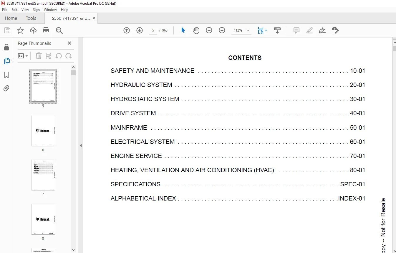
TABLE OF CONTENTS:
Bobcat S550 Skid-Steer Loader Service Manual SN B4ZD11001 & Above – PDF DOWNLOAD
MAINTENANCE SAFETY 3
CONTENTS 5
FOREWORD 7
FOREWORD 9
SAFETY INSTRUCTIONS 11
FIRE PREVENTION 13
Maintenance 13
Operation 13
Electrical 13
Hydraulic System 13
Fueling 13
Starting 13
Spark Arrester Exhaust System 13
Welding And Grinding 14
Fire Extinguishers 14
SERIAL NUMBER LOCATIONS 15
Loader Serial Number 15
Engine Serial Number 15
DELIVERY REPORT 16
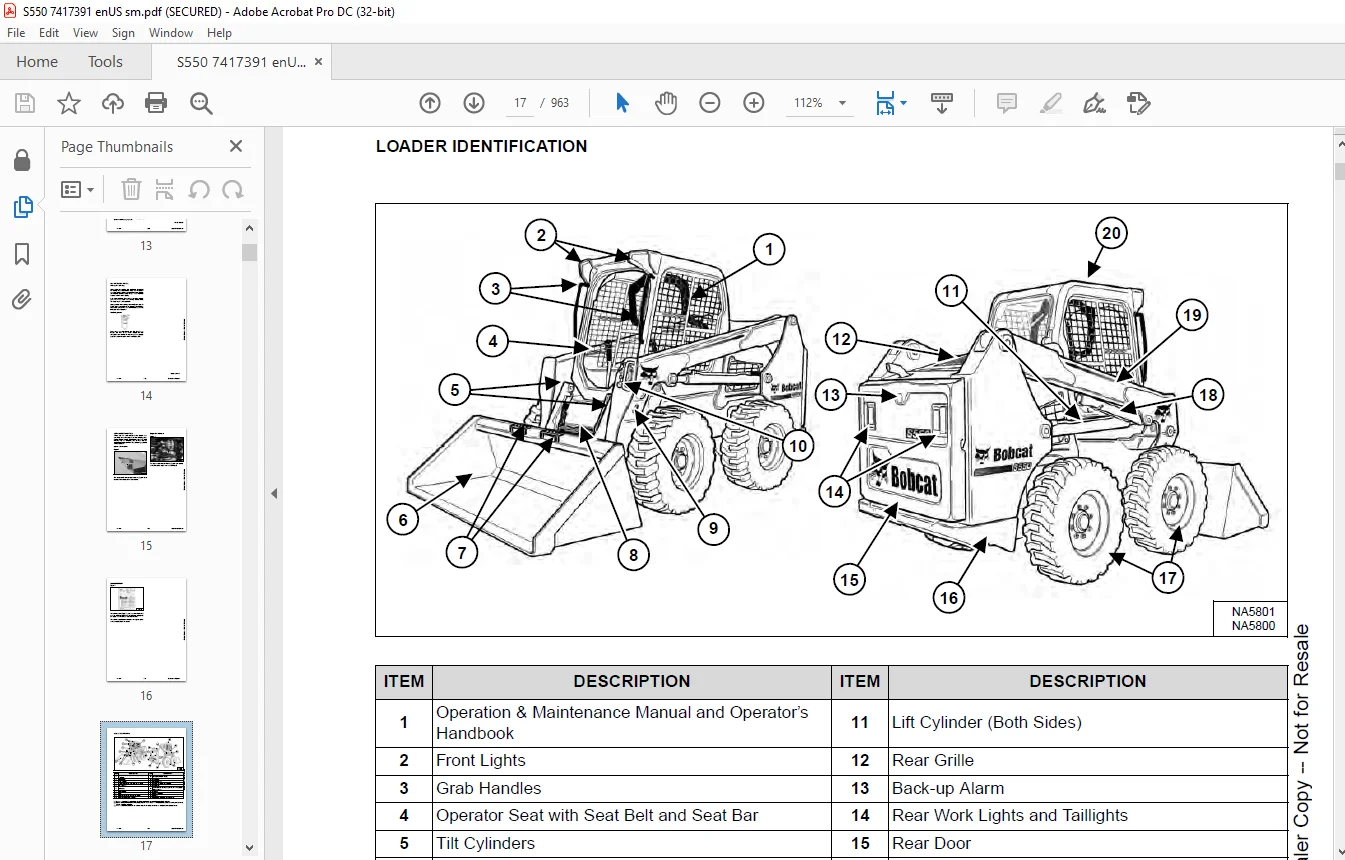
LOADER IDENTIFICATION 17
SAFETY AND MAINTENANCE 19
LIFTING AND BLOCKING THE LOADER 23
Procedure 23
LIFT ARM SUPPORT 25
Description 25
Installing 26
Removing 27
OPERATOR CAB 29
Description 29
Cab Door Sensor 29
Raising 30
Lowering 31
Special Applications Kit 32
Special Applications Kit Inspection And Maintenance 32
Forestry Door And Window Kit 33
Forestry Door And Window Kit Inspection And Maintenance 33
TRANSPORTING THE LOADER ON A TRAILER 35
Loading And Unloading 35
Fastening 35
TOWING THE LOADER 37
Procedure 37
REMOTE START TOOL KIT – MEL1563 39
Remote Start Tool – MEL1563 39
Service Tool Harness Communicator – MEL1566 41
Remote Start Procedure 41
REMOTE START TOOL (SERVICE TOOL) KIT – 7217666 45
Description 45
Remote Start Tool (Service Tool) – 7022042 46
Loader Service Tool Harness – 6689747 47
Computer Service Tool Harness – 6689746 48
Remote Start Procedure 49
SERVICE SCHEDULE 53
Maintenance Intervals 53
ENGINE AIR CLEANER 55
Replacing Filters 55
ENGINE COOLING SYSTEM 57
Maintenance Platform 57
Cleaning 57
Checking And Adding Coolant 60
Removing And Replacing Coolant 61
FUEL SYSTEM 63
Fuel Specifications 63
Biodiesel Blend Fuel 63
Filling The Fuel Tank 64
Fuel Filter 65
Replacing Fuel Pre-Filter 66
Replacing Main Fuel Filter 67
ENGINE LUBRICATION SYSTEM 69
Checking And Adding Engine Oil 69
Engine Oil Chart 69
Removing And Replacing Oil And Filter 70
HYDRAULIC / HYDROSTATIC SYSTEM 73
Checking And Adding Fluid 73
Hydraulic / Hydrostatic Fluid Chart 73
Removing And Replacing Hydraulic Fluid 74
Removing And Replacing Hydraulic / Hydrostatic Filter 76
Removing And Replacing Hydraulic Charge Filter 77
Replacing Reservoir Breather Cap 78
FINAL DRIVE TRANSMISSION (CHAINCASE) 79
Checking And Adding Fluid 79
Removing And Replacing Fluid 79
BOB-TACH (HAND LEVER) 81
Inspection And Maintenance 81
BOB-TACH (POWER) 83
Inspection And Maintenance 83
LUBRICATING THE LOADER 85
Lubrication Locations 85
TIRE MAINTENANCE 89
Wheel Nuts 89
Rotating 89
Mounting 90
PIVOT PINS 91
Inspection And Maintenance 91
LOADER STORAGE AND RETURN TO SERVICE 93
Storage 93
Return To Service 93
STOPPING THE ENGINE AND LEAVING THE LOADER 95
Procedure 95
EMERGENCY EXIT 97
Rear Window Identification 97
Rear Window Removal (Latches) 97
Rear Window Removal (Rubber Cord) 97
External Access (Rear Window With Latches) 98
External Access (Rear Window With Rubber Cord) 98
Front Door 98
SEAT BELT 101
Inspection And Maintenance 101
HYDRAULIC SYSTEM 103
HYDRAULIC / HYDROSTATIC SCHEMATICS 107
HYDRAULIC SYSTEM INFORMATION 115
Glossary Of Hydraulic / Hydrostatic Symbols 115
Troubleshooting 119
CYLINDER (LIFT) 121
Testing 121
Removal And Installation 122
Parts Identification 125
Disassembly 126
Assembly 128
CYLINDER (TILT) 133
Testing 133
Removal And Installation 134
Base End Pivot Pin Removal And Installation 135
Parts Identification 136
Disassembly 137
Assembly 139
CYLINDER (BOB-TACH) 143
Testing 143
Removal And Installation 144
Parts Identification 145
Disassembly 146
Assembly 148
MAIN RELIEF VALVE 151
Description 151
Testing 152
Adjusting 154
Removal And Installation 155
HYDRAULIC CONTROL VALVE (STANDARD) 157
Description 157
Removal And Installation 158
Mount Bracket Removal And Installation 161
Identification Chart 162
Lift Load Check Valve Removal And Installation 163
Load Check Valve Removal And Installation (Tilt And Auxiliary) 164
Anti-Cavitation Valve Removal And Installation (Lift, Rod End) 165
Port Relief / Anti-Cavitation Valve Removal And Installation (Lift, Base End) 165
Port Relief / Anti-Cavitation Valve Removal And Installation (Tilt, Base End) 166
Port Relief / Anti-Cavitation Valve Removal And Installation (Tilt, Rod End) 166
Port Relief Valve Removal And Installation 167
Plug Removal And Installation 168
Rubber Boot Removal And Installation 169
End Cap Block Removal And Installation 169
Lift Spool And Detent Removal And Installation 170
Tilt Spool Removal And Installation 178
Auxiliary Spool Removal And Installation 180
Auxiliary Solenoid Removal And Installation 181
Solenoid Removal And Installation 182
Lock Valve Removal And Installation 183
Lift Arm Bypass Orifice Removal And Installation 185
Main Relief Valve Removal And Installation 185
Check Valve Removal And Installation 186
HYDRAULIC CONTROL VALVE (SJC) 189
Description 189
Removal And Installation 189
Actuator Removal And Installation (In Loader) 193
Actuator Removal And Installation (Out Of Loader) 195
Identification Chart 198
Mount Bracket Removal And Installation 199
Lift Load Check Valve Removal And Installation 199
Load Check Valve Removal And Installation (Tilt And Auxiliary) 200
Anti-Cavitation Valve Removal And Installation (Lift, Rod End) 201
Port Relief / Anti-Cavitation Valve Removal And Installation (Lift, Base End) 201
Port Relief / Anti-Cavitation Valve Removal And Installation (Tilt, Base End) 202
Port Relief / Anti-Cavitation Valve Removal And Installation (Tilt, Rod End) 202
Port Relief Valve Removal And Installation 203
Plug Removal And Installation 204
End Cap Block Removal And Installation 205
Lift Spool Removal And Installation 205
Lift Spool Disassembly And Assembly 207
Tilt Spool Removal And Installation 208
Auxiliary Spool Removal And Installation 210
Auxiliary Solenoid Removal And Installation 211
Solenoid Removal And Installation 212
Lock Valve Removal And Installation 213
Lift Arm Bypass Orifice Removal And Installation 215
Main Relief Valve Removal And Installation 215
Check Valve Removal And Installation 216
LIFT ARM BYPASS CONTROL VALVE 217
Description 217
Testing 217
Removal And Installation 218
Bracket Removal And Installation 219
Disassembly And Assembly 219
HYDRAULIC PUMP 221
Description 221
Pump Test At Quick Couplers 222
Direct Pump Test (Standard Section) 224
Direct Pump Test (Charge Section) 226
Removal And Installation 228
Hydraulic Pump Startup 230
Parts Identification 231
Disassembly And Assembly 232
HYDRAULIC PUMP (HIGH FLOW) 233
Description 233
Pump Test At Quick Couplers 234
Direct Pump Test (Standard Section) 236
Direct Pump Test (Charge Section) 237
Direct Pump Test (High Flow Section) 239
High Flow Relief Valve Adjustment 241
High Flow Relief Valve Removal And Installation 243
Solenoid Removal And Installation 244
Removal And Installation 245
Hydraulic Pump Startup 247
Parts Identification 248
Disassembly And Assembly 249
HYDRAULIC / HYDROSTATIC FILTERS 251
Description 251
Housing Removal And Installation 251
HYDRAULIC FLUID RESERVOIR 253
Description 253
Removal And Installation 253
Hydraulic Fluid Screen 254
OIL COOLER 255
Removal And Installation 255
BUCKET POSITION VALVE 257
Description 257
Removal And Installation 257
Solenoid Testing 258
Disassembly And Assembly 259
REAR AUXILIARY DIVERTER VALVE 261
Description 261
Solenoid Testing 261
Removal And Installation 262
Disassembly And Assembly 263
BOB-TACH (POWER) BLOCK 269
Description 269
Testing Relief Valve 270
Removal And Installation 272
Disassembly And Assembly 274
FRONT AUXILIARY HYDRAULIC COUPLER BLOCK 279
Description 279
Removal And Installation 279
Disassembly And Assembly 279
AUTOMATIC RIDE CONTROL 283
Description 283
Removal And Installation 283
Checking The Pressure In The Accumulator 285
Adding Nitrogen To The Accumulator 287
HYDROSTATIC SYSTEM 289
HYDROSTATIC SYSTEM INFORMATION 291
Description 291
Troubleshooting 292
HYDROSTATIC DRIVE MOTOR 293
Description 293
Removal And Installation 293
Parts Identification 296
Disassembly And Assembly 297
HYDROSTATIC DRIVE MOTOR (TWO-SPEED) 303
Description 303
Removal And Installation (Left Side) 304
Removal And Installation (Right Side) 307
Parts Identification 310
Disassembly 311
Assembly 324
HYDROSTATIC MOTOR CARRIER 339
Description 339
Shaft Seal Removal And Installation 340
Removal And Installation 342
Parts Identification 344
Disassembly 345
Assembly 347
HYDROSTATIC MOTOR CARRIER (TWO-SPEED) 351
Description 351
Shaft Seal Removal And Installation 352
Removal And Installation 354
Parts Identification 356
Disassembly 357
Assembly 359
CHARGE PRESSURE 363
Description 363
Testing 364
Adjusting 366
Sender Removal And Installation (Earlier Models) 368
Sender Removal And Installation (Later Models) 368
HYDROSTATIC PUMP 369
Description 369
Removal And Installation 370
Hydrostatic Pump Startup 371
Replenishing / High Pressure Relief Valve Removal And Installation 372
Parts Identification (Left Half) 373
Parts Identification (Right Half) 374
Disassembly 375
Assembly 382
HYDROSTATIC PUMP (SJC) 389
Description 389
Port Locations And Gauge Installation 390
Removal And Installation 391
Hydrostatic Pump Startup 393
Parts Identification 394
High Pressure Relief And Bypass Valve 397
Charge Pressure Relief Valve 398
Disassembly And Assembly 399
Mechanical Neutral Adjustment 411
Hydraulic Controller Neutral Adjustment 413
DRIVE BELT 415
Belt Adjustment 415
Stop Adjustment 415
Belt Replacement 416
Tensioner Pulley Removal And Installation (Earlier Models) 418
Tensioner Pulley Disassembly And Assembly 418
Tensioner Pulley Removal And Installation (Later Models) 419
Tensioner Pulley Disassembly And Assembly 419
TWO-SPEED 421
Valve Block Removal And Installation 421
Valve Block Disassembly And Assembly 422
DRAIN MANIFOLD 423
Description 423
Drain Manifold Removal And Installation 423
DRIVE SYSTEM 425
BRAKE 427
Description 427
Disc Removal And Installation 427
DRIVE COMPONENTS 429
Description 429
Axle Seal Removal And Installation 430
Axle, Sprocket And Bearings Removal And Installation 432
Chain Removal And Installation 437
CHAINCASE 439
Description 439
Front Cover Removal And Installation 439
Center Cover Removal And Installation 440
Rear Cover Removal And Installation 441
MAINFRAME 443
SEAT BAR 447
Description 447
Removal And Installation 447
Disassembly And Assembly 448
Compression Spring Disassembly And Assembly 449
OPERATOR CAB 451
Gas Spring Removal And Installation 451
Gas Spring Bracket Disassembly And Assembly 452
Removal And Installation 452
OPERATOR SEAT 455
Removal And Installation 455
Seat Belt Removal And Installation (Retractable) 455
Seat Belt And Bracket Removal And Installation (Standard) 456
Seat Belt Bracket Removal And Installation 456
OPERATOR SEAT (SUSPENSION) 457
Removal And Installation 457
Slide Rail Removal And Installation 457
Seat Belt Removal And Installation 458
Lower Cushion Removal 458
Lower Cushion Installation 459
Back Cushion Removal And Installation 459
Shock Removal And Installation 460
3-Point Seat Belt Removal And Installation 460
BOB-TACH (HAND LEVER) 463
Description 463
Removal And Installation 463
Lever And Wedge Disassembly And Assembly 466
Pivot Pin Bushing And Seal Removal And Installation 468
BOB-TACH (POWER) 469
Description 469
Removal And Installation 469
Lever And Wedge Disassembly And Assembly 472
Pivot Pin Bushing And Seal Removal And Installation 474
LIFT ARMS 475
Stabilizer Bar Removal And Installation 475
REAR GRILLE 477
Removing 477
Installing 477
Shield Removal And Installation 478
REAR DOOR (TAILGATE) 479
Removal And Installation 479
Striker Removal And Installation 480
Striker Disassembly And Assembly 480
Striker Adjusting 481
Latch Removal And Installation 482
FUEL TANK 483
Removal And Installation 483
Fuel Level Sender Removal And Installation 485
CONTROL PEDALS AND LINKAGES 487
Description 487
Pedal Removal And Installation 487
Linkage Removal And Installation 488
Pedal (Adjusting) 489
Floor Pan Removal And Installation 490
CONTROL PANEL 491
Description 491
Removal And Installation 492
Disassembly And Assembly 493
Linkage Removal And Installation 498
Pintle Arm Disassembly And Assembly 501
Linkage Neutral (Adjusting) 502
Linkage Travel (Adjusting) 506
Shock Removal And Installation 510
CONTROL PANEL (SJC) 511
Description 511
Removal And Installation 511
CONTROL HANDLE / LEVER 513
Description 513
Lever Removal And Installation 513
Boot Removal And Installation 514
CONTROL HANDLE / LEVER (SJC) 515
Description 515
Joystick Testing 515
Joystick Removal And Installation 516
ACCESS PANEL (INSIDE) 517
Removal And Installation (Left) 517
Removal And Installation (Right) 517
ACCESS PANEL (INSIDE) (SJC) 519
Removal And Installation (Left) 519
Removal And Installation (Right) 519
WINDOW (REAR) 521
Rear Window Identification 521
Rear Window Removal (Latches) 521
Rear Window Removal (Rubber Cord) 521
External Access (Rear Window With Latches) 522
External Access (Rear Window With Rubber Cord) 522
Disassembly And Assembly (Latches) 523
WINDOW (TOP) 525
Removal And Installation 525
WINDOW (SIDE) 527
Removal And Installation 527
CAB DOOR 529
Description 529
Removal And Installation 529
Disassembly And Assembly 530
Aligning 531
Adjusting 532
Checking Operation 532
ARMREST 533
Description 533
Removal And Installation 534
Disassembly And Assembly 535
LEFT SIDE LOWER PANEL 537
Removal And Installation 537
Disassembly And Assembly 540
RIGHT SIDE LOWER PANEL 541
Removal And Installation 541
Disassembly And Assembly 543
HEADLINER 545
Removal And Installation 545
FAN DUCT PANELS 547
Removal And Installation 547
ELECTRICAL SYSTEM 549
ELECTRICAL SCHEMATICS 553
ELECTRICAL SYSTEM INFORMATION 586
Glossary Of Electrical Symbols 586
Standard Cab Harness Connectors 589
Deluxe Cab Harness Connectors 590
Mainframe Harness Connectors 591
Description 592
Troubleshooting 593
Fuse And Relay Location / Identification 594
Solenoid Testing 597
BATTERY 598
Removal And Installation 598
Battery Maintenance 599
Maintaining Battery Charge Level 599
Battery Service During Machine Storage 599
Battery Testing 600
Battery Charging 600
Using A Booster Battery (Jump Starting) 601
ALTERNATOR 602
Belt Adjustment 602
Belt Replacement 602
Charging System Inspection 603
Alternator Voltage Testing 604
Low Voltage Testing 604
High Voltage Testing 605
Removal And Installation 606
Parts Identification 608
STARTER 610
Testing 610
Removal And Installation 610
Parts Identification 611
INSTRUMENT PANEL IDENTIFICATION 612
Overview 612
Left Panel 613
Display Screen 615
Right Panel 616
Left Switch Panel 618
Right Switch Panel 618
Left Side Lower Panel 619
Right Side Lower Panel 619
Left Panel Removal And Installation 620
Right Panel Removal And Installation 620
Key Switch Disassembly And Assembly 621
Alarm Disassembly And Assembly 621
Left Switch Panel Removal And Installation 622
Right Switch Panel Removal And Installation 622
LIGHTS 624
Front Removal And Installation 624
Rear Removal And Installation 625
Cab Light Removal And Installation 625
BOBCAT CONTROLLERS (GATEWAY AND AUXILIARY) 626
Description 626
Connector Identification 627
Removal And Installation 633
BOBCAT CONTROLLER (SJC) (DRIVE) 634
Description 634
Connector Identification 635
Removal And Installation 637
ENGINE CONTROL UNIT (ECU) 638
Description 638
Cleaning 639
Removal And Installation 640
DIAGNOSTIC SERVICE CODES 642
Viewing Service Codes 642
Service Codes List 643
BOBCAT INTERLOCK CONTROL SYSTEM (BICS™) 658
Description 658
Inspecting The BICS™ (Engine STOPPED – Key ON) 659
Inspecting Deactivation Of The Auxiliary Hydraulics System (Engine STOPPED – Key ON) 659
Inspecting The Seat Bar Sensor (Engine RUNNING) 659
Inspecting The Traction Lock And Parking Brake (Engine RUNNING) 659
Inspecting The Lift Arm Bypass Control 659
Inspecting Deactivation Of Lift And Tilt Functions (ACS And SJC) 659
Troubleshooting 660
SEAT BAR SENSOR 662
Description 662
Troubleshooting 662
Testing 663
Removal 664
Installation 666
Bobcat Interlock Control System (BICS™) Circuit Test 667
TRACTION LOCK 670
Description 670
Troubleshooting 671
Inspecting 672
ELECTRICAL / HYDRAULIC CONTROLS (MANUAL) 674
Identification Chart 674
Description 675
Identification Chart ACD Group 0 676
Identification Chart ACD Group 1 677
Identification Chart ACD Group 2 678
Identification Chart ACD Group 3 679
ELECTRICAL / HYDRAULIC CONTROLS (SJC) 680
Identification Chart 680
Description 681
Identification Chart ACD Group 0 682
Identification Chart ACD Group 1 683
Identification Chart ACD Group 2 684
Identification Chart ACD Group 3 685
SERVICE PC (LAPTOP COMPUTER) 686
Connecting Remote Start Tool (Service Tool) 686
CALIBRATION 688
Description 688
Actuator Testing 688
Lift And Tilt Calibration (SJC) 691
Hydrostatic Pump Calibration (SJC) 693
STEERING DRIFT COMPENSATION (OPERATOR MODE) 698
Description 698
Operation 698
STEERING DRIFT COMPENSATION (SERVICE MODE) 700
Description 700
Operation 700
CONTROL PANEL SETUP 702
Right Panel Setup (Deluxe Instrumentation Panel) 702
PASSWORD SETUP (DELUXE INSTRUMENTATION PANEL) 706
Password Description 706
Changing The Owner Password 706
Changing The User Passwords 707
Password Lockout Feature 707
MAINTENANCE CLOCK 708
Description 708
Setup 709
Reset 709
BACK-UP ALARM SYSTEM 710
Description 710
Inspecting 710
Adjusting Switch Position 711
Troubleshooting (Standard) 712
Troubleshooting (Joystick) 713
Alarm Removal And Installation 714
Switch Removal And Installation 714
FRONT HORN 716
Removal And Installation 716
Troubleshooting 717
Troubleshooting (Joystick) 718
ENGINE SPEED CONTROL (HAND) 720
Removal And Installation 720
ENGINE SPEED CONTROL (FOOT) 722
Removal And Installation 722
Disassembly And Assembly 723
Foot Throttle Calibration 725
CAMSHAFT AND CRANKSHAFT POSITION SENSOR 728
Removal And Installation 728
MACHINE IQ 730
Description 730
Removal And Installation 730
Procedure 731
ENGINE SERVICE 732
ENGINE INFORMATION 736
Description 736
Specifications 737
Sensor Location 739
Torque Values 744
Troubleshooting 746
Engine Removal And Installation 748
Engine Mount Replacement 756
Compression – Testing 758
Injector Signal – Testing 760
Injector Signal – Testing (In-Line) 762
DIESEL PARTICULATE FILTER (DPF) SYSTEM 764
Description 764
Removal And Installation 764
DPF Icons 765
DPF Regeneration Tables 766
Automatic Regeneration Operation 767
Forced Regeneration Operation 768
Forced Parked Regeneration Operation 769
Inhibit Mode Operation 770
AIR CLEANER 772
Housing Removal And Installation 772
ENGINE COOLING SYSTEM 774
Radiator / Oil Cooler Removal And Installation 774
Hydraulic Fan Description 776
Reversible Hydraulic Fan Description 777
Fan Duct Removal And Installation 777
Hydraulic Fan Motor Assembly Removal And Installation 778
Hydraulic Fan Motor Removal And Installation 779
Hydraulic Fan Motor Disassembly And Assembly 781
Blower Housing Removal And Installation 789
Water Pump Removal And Installation 790
Thermostat Housing Removal And Installation 791
Testing The Thermostat 792
LUBRICATION SYSTEM 794
Description 794
Oil Pan Removal And Installation 795
Oil Pump Removal And Installation 796
Oil Pump Relief Valve Description 797
Oil Pump Relief Valve Removal And Installation 797
Oil Cooler Removal And Installation 798
Oil Filter Head Removal And Installation 799
Oil Cooler Bypass Description 800
Oil Cooler Bypass Removal And Installation 800
FUEL SYSTEM 802
Description 802
Fuel Filter Housing Removal And Installation 803
Fuel Lift Pump Removal And Installation 805
Transfer Pump / High Pressure Pump Removal And Installation 805
Fuel Temperature Sensor Removal And Installation 807
Fuel Cooler Removal And Installation 808
Fuel Recirculation Valve (FRV) Removal And Installation 808
Fuel Injector Removal And Installation 809
Injector Coding 811
CYLINDER HEAD 812
Glow Plugs Testing 812
Glow Plug Removal And Installation 813
Cylinder Head Removal And Installation 814
Cylinder Head Disassembly And Assembly 819
Cylinder Head Inspection 820
Cylinder Head Top Clearance 821
Valve Step Height 822
Valve Stem Height 822
Valve Guide 823
Valve 823
Valve Spring 824
Rocker Arm Shaft Disassembly And Assembly 825
Rocker Arm Shaft Inspection 826
Push Rod Inspection 826
CRANKSHAFT AND PISTONS 828
Piston And Connecting Rod Removal And Installation 828
Piston And Connecting Rod Inspection 829
Crankshaft Removal And Installation 831
Cylinder Block Inspection 834
Crankshaft Inspection 836
Connecting Rod Inspection 836
Engine Component Class 837
CAMSHAFT 840
Removal And Installation 840
Inspecting 841
GEARCASE 844
Gearcase Cover Removal And Installation 844
Gear Backlash 845
Gear Timing 846
Idle Gear Removal And Installation 847
Idle Gear Inspection 847
TURBOCHARGER 848
Description 848
Removal And Installation 848
Inspection 851
FLYWHEEL AND HOUSING 852
Flywheel Removal And Installation 852
Ring Gear Removal And Installation 853
Housing Removal And Installation 853
EXHAUST GAS RECIRCULATION (EGR) SYSTEM 854
Description 854
Removal And Installation 855
HEATING, VENTILATION AND AIR CONDITIONING (HVAC) 858
AIR CONDITIONING SYSTEM FLOW 860
Description 860
Chart 861
Components 862
Safety Equipment 865
REGULAR MAINTENANCE 866
Filters 866
Belt Adjustment 867
Belt Replacement 867
Air Conditioning Condenser 867
Air Conditioning Lubrication 867
Air Conditioning Service Chart 868
Evaporator / Heater Coil 869
TROUBLESHOOTING 872
Blower Motor Does Not Operate 872
Blower Motor Operates Normally, But Air Flow Is Insufficient 872
Insufficient Cooling Although Air Flow And Compressor Operation Are Normal 872
The Compressor Does Not Operate At All, Or Operates Improperly 872
Gauge Pressure Related Troubleshooting 873
Troubleshooting Tree 875
Temperature / Pressure Chart 879
Poor A/C Performance 881
HVAC Repair And Leaks 882
Electrical System 883
Engine Coolant Bypassing The Heater Valve 889
Heater Valve Not Opening Or Closing 890
SYSTEM CHARGING AND RECLAMATION 892
Refrigerant Identification 892
Reclamation And Charging With Recovery / Charging Unit 893
COMPRESSOR 896
Removal And Installation 896
Oil 898
Oil Check 899
CONDENSER 902
Removal And Installation 902
RECEIVER / DRIER 904
Receiver / Drier Removal And Installation 904
Pressure Switch Removal And Installation 906
Schrader® Valve Removal And Installation 907
EVAPORATOR / HEATER UNIT 908
Removal And Installation 908
THERMOSTAT 910
Description 910
Removal And Installation 911
EXPANSION VALVE 912
Removal And Installation 912
EVAPORATOR COIL 914
Removal And Installation 914
HEATER COIL 916
Removal And Installation 916
BLOWER FAN 918
Removal And Installation 918
Disassembly And Assembly 918
HEATER VALVE 922
Removal And Installation 922
EVAPORATOR / HEATER COVER 924
Removing 924
Installing 924
SPECIFICATIONS 926
(S550) LOADER SPECIFICATIONS 928
Machine Dimensions 928
Performance 929
Engine 929
Drive System 930
Controls 930
Hydraulic System 931
Electrical System 932
Capacities 932
Tires 933
Environmental 933
Engine CO2 Emission Values 933
Temperature Range 933
TECHINCAL SERVICE GUIDE SPECIFICATIONS 934
Engine 934
Engine Torques 934
Cooling System 934
Loader Torques 935
Hydraulic / Hydrostatic System 935
Fuel Consumption 935
TORQUE SPECIFICATIONS FOR BOLTS 936
Torque For General SAE Bolts 936
Torque For General Metric Bolts 937
HYDRAULIC CONNECTION SPECIFICATIONS 938
Straight Thread O-ring Fitting 938
Flare Fitting 939
Tubelines And Hoses 939
HYDRAULIC / HYDROSTATIC FLUID SPECIFICATIONS 940
Specifications 940
CONVERSIONS 942
Decimal And Millimeter Equivalent Chart 942
U S To Metric Conversion Chart 942
SERVICE TOOLS REQUIRED 944
Remote Start Tools 944
Hydraulic Tools 945
Mainframe And Drive Tools 948
Electrical Tools 951
Engine Tools 952
HVAC Tools 957
ALPHABETICAL INDEX 958
IMAGES PREVIEW OF THE MANUAL:
Need help? Contact: [email protected]
PLEASE NOTE:
- This is the same manual used by the DEALERSHIPS to SERVICE your vehicle.
- The manual can be all yours – Once payment is complete, you will be taken to the download page from where you can download the manual. All in 2-5 minutes time!!
- Need any other service / repair / parts manual, please feel free to contact us at heydownloadss @gmail.com . We may surprise you with a nice offer
S.V


