Bobcat S570 Compact Track Loader Service Manual 6989675 – PDF DOWNLOAD
$36.95
Bobcat S570 Compact Track Loader Service Manual 6989675 – PDF DOWNLOAD
S/N A7U711001 & Above
S/N A7U811001 & Above
S/N AZNB11001 & Above
S/N AZNC11001 & Above
Description
Bobcat S570 Compact Track Loader Service Manual 6989675 – PDF DOWNLOAD
FILE DETAILS:
Bobcat S570 Compact Track Loader Service Manual 6989675 – PDF DOWNLOAD
Language : English
Pages : 1240
Downloadable : Yes
File Type : PDF
DESCRIPTION:
Bobcat S570 Compact Track Loader Service Manual 6989675 – PDF DOWNLOAD
S/N A7U711001 & Above
S/N A7U811001 & Above
S/N AZNB11001 & Above
S/N AZNC11001 & Above
FOREWORD:
This manual is for the Bobcat loader mechanic. It provides necessary servicing and adjustment procedures for the Bobcat loader and its component parts and systems. Refer to the Operation & Maintenance Manual for operating instructions, starting procedure, daily checks, etc.
A general inspection of the following items must be made after the loader has had service or repair:
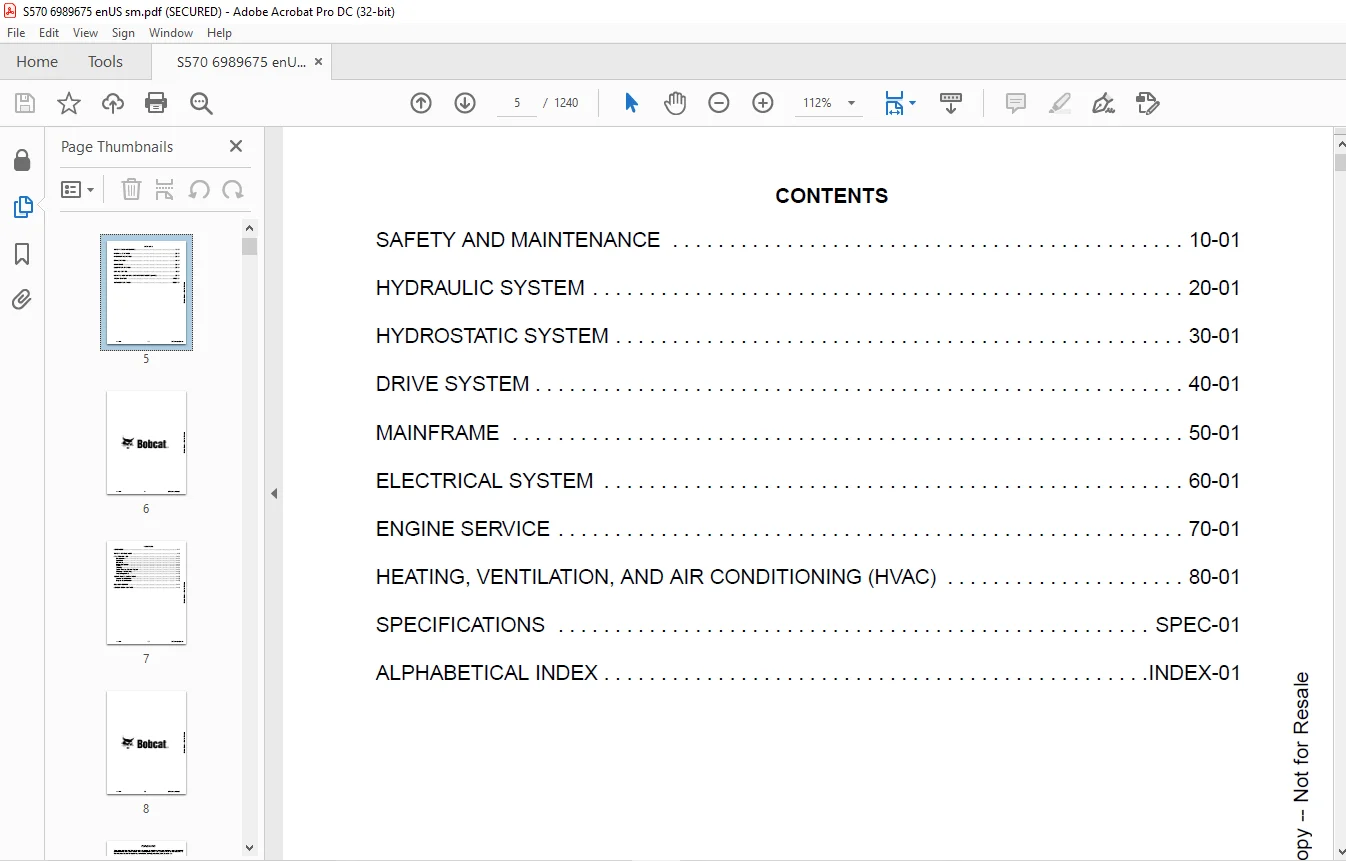
TABLE OF CONTENTS:
Bobcat S570 Compact Track Loader Service Manual 6989675 – PDF DOWNLOAD
MAINTENANCE SAFETY 3
CONTENTS 5
FOREWORD 7
FOREWORD 9
SAFETY INSTRUCTIONS 11
FIRE PREVENTION 13
Maintenance 13
Operation 13
Electrical 13
Hydraulic System 13
Fueling 13
Starting 13
Spark Arrester Exhaust System 13
Welding And Grinding 14
Fire Extinguishers 14
SERIAL NUMBER LOCATIONS 15
Loader Serial Number 15
Engine Serial Number 15
DELIVERY REPORT 16
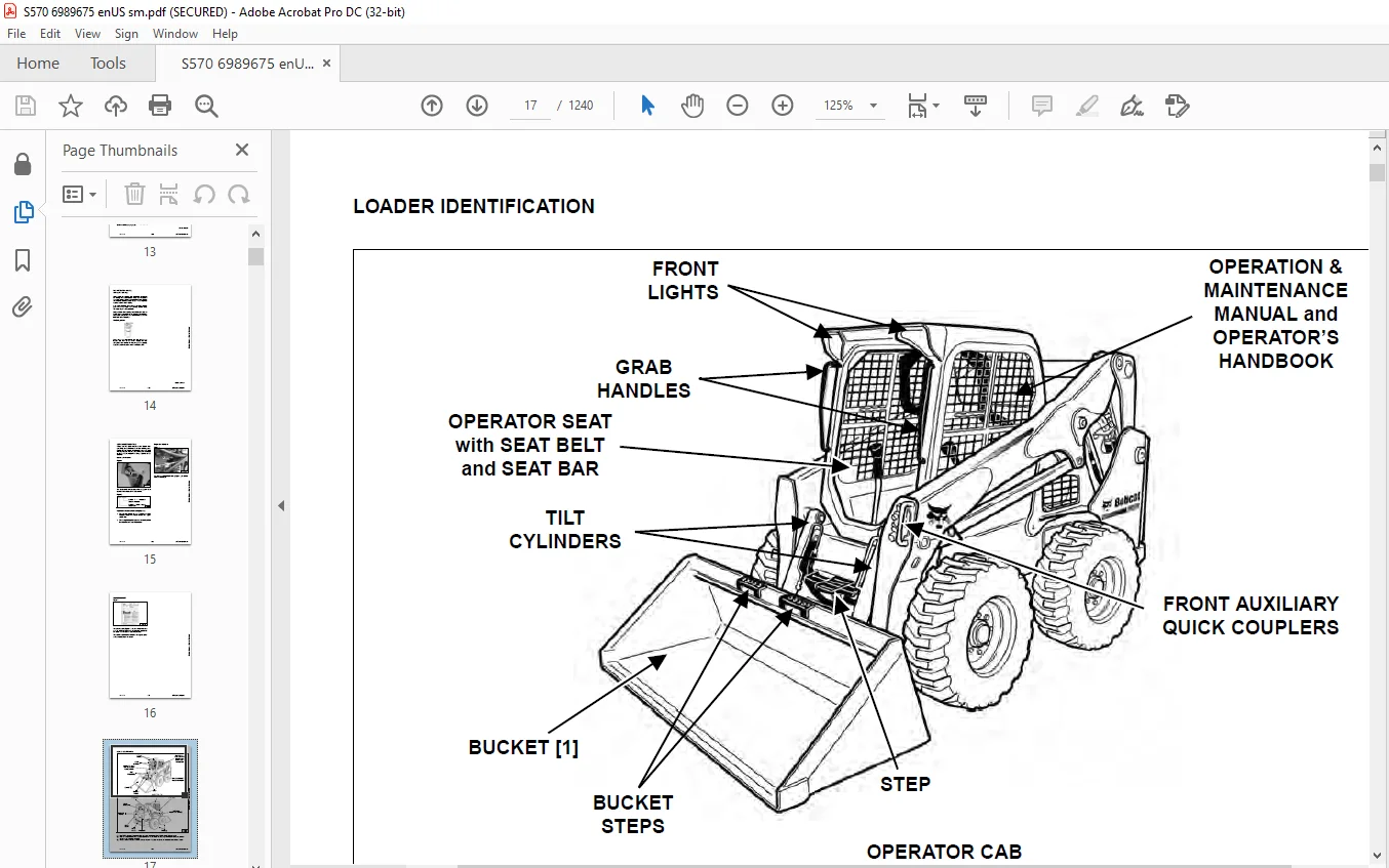
LOADER IDENTIFICATION 17
SAFETY AND MAINTENANCE 19
LIFTING AND BLOCKING THE LOADER 23
Procedure 23
LIFT ARM SUPPORT DEVICE 25
Description 25
Installing 26
Removing 27
OPERATOR CAB 29
Description 29
Raising 30
Lowering 31
Cab Door Sensor 32
Special Applications Kit 32
Special Applications Kit Inspection And Maintenance 32
Forestry Door And Window Kit 33
Forestry Door And Window Kit Inspection And Maintenance 33
TRANSPORTING THE LOADER ON A TRAILER 35
Loading And Unloading 35
Fastening 35
TOWING THE LOADER 37
Procedure 37
REMOTE START TOOL KIT – MEL1563 39
Remote Start Tool – MEL1563 39
Service Tool Harness Communicator – MEL1566 41
Remote Start Procedure 41
REMOTE START TOOL (SERVICE TOOL) KIT – 7217666 45
Description 45
Remote Start Tool (Service Tool) – 7022042 46
Loader Service Tool Harness – 6689747 47
Computer Service Tool Harness – 6689746 48
Remote Start Procedure 49
SERVICE SCHEDULE 53
Maintenance Intervals 53
ENGINE AIR CLEANER 55
Replacing Filters 55
ENGINE COOLING SYSTEM (EARLIER MODELS) 57
Maintenance Platform 57
Cooling System Identification 57
Cleaning (Earlier Models) 58
Checking And Adding Coolant 60
Removing And Replacing Coolant 61
ENGINE COOLING SYSTEM (LATER MODELS) 63
Maintenance Platform 63
Cleaning 63
Checking And Adding Coolant 65
Removing And Replacing Coolant 66
FUEL SYSTEM 67
Fuel Specifications 67
Biodiesel Blend Fuel 67
Filling The Fuel Tank 68
Fuel Filter 69
Removing Air From The Fuel System 70
ENGINE LUBRICATION SYSTEM 71
Checking And Adding Engine Oil 71
Engine Oil Chart 71
Removing And Replacing Oil And Filter 72
HYDRAULIC / HYDROSTATIC SYSTEM (EARLIER MODELS) 73
Checking And Adding Fluid 73
Hydraulic / Hydrostatic Fluid Chart 73
Removing And Replacing Hydraulic Fluid 74
Removing And Replacing Hydraulic / Hydrostatic Filter 76
Removing And Replacing Hydraulic Charge Filter 77
Replacing Reservoir Breather Cap 78
HYDRAULIC / HYDROSTATIC SYSTEM (LATER MODELS) 79
Checking And Adding Fluid 79
Hydraulic / Hydrostatic Fluid Chart 79
Removing And Replacing Hydraulic Fluid 80
Removing And Replacing Hydraulic / Hydrostatic Filter 82
Removing And Replacing Hydraulic Charge Filter 83
Replacing Reservoir Breather Cap 84
FINAL DRIVE TRANSMISSION (CHAINCASE) 85
Checking And Adding Fluid 85
Removing And Replacing Fluid 85
BOB-TACH (HAND LEVER) 87
Inspection And Maintenance 87
BOB-TACH (POWER) 89
Inspection And Maintenance 89
LUBRICATING THE LOADER 91
Lubrication Locations 91
TIRE MAINTENANCE 95
Wheel Nuts 95
Rotating 95
Mounting 96
SPARK ARRESTER MUFFLER 97
Cleaning Procedure 97
PIVOT PINS 99
Inspection And Maintenance 99
LOADER STORAGE AND RETURN TO SERVICE 101
Storage 101
Return To Service 101
STOPPING THE ENGINE AND LEAVING THE LOADER 103
Procedure 103
EMERGENCY EXIT 105
Rear Window Identification 105
Rear Window Removal (Latches) 105
Rear Window Removal (Rubber Cord) 105
External Access (Rear Window With Latches) 106
External Access (Rear Window With Rubber Cord) 106
Front Door 106
SEAT BELT 109
Inspection And Maintenance 109
HYDRAULIC SYSTEM 111
HYDRAULIC / HYDROSTATIC SCHEMATICS 115
HYDRAULIC SYSTEM INFORMATION 131
Glossary Of Hydraulic / Hydrostatic Symbols 131
Troubleshooting 135
CYLINDER (LIFT) 137
Testing 137
Removal And Installation 138
Parts Identification 142
Disassembly 143
Assembly 145
CYLINDER (TILT) 149
Testing 149
Removal And Installation 150
Base End Pivot Pin Removal And Installation 151
Parts Identification 152
Disassembly 153
Assembly 155
CYLINDER (LIFT) (AZNB11488 & ABOVE) 159
Testing 159
Removal And Installation 160
Parts Identification 164
Disassembly 165
Assembly 167
CYLINDER (TILT) (AZNB11488 & ABOVE) 171
Testing 171
Removal And Installation 172
Base End Pivot Pin Removal And Installation 173
Parts Identification 174
Disassembly 175
Assembly 177
CYLINDER (BOB-TACH) 181
Testing 181
Removal And Installation 182
Parts Identification 183
Disassembly 184
Assembly 185
MAIN RELIEF VALVE 189
Description 189
Testing 190
Adjusting 192
Removal And Installation 193
HYDRAULIC CONTROL VALVE (STANDARD) 195
Description 195
Removal And Installation 196
Mount Bracket Removal And Installation 199
Identification Chart 200
Lift Load Check Valve Removal And Installation 201
Load Check Valve Removal And Installation (Tilt And Auxiliary) 202
Anti-Cavitation Valve Removal And Installation (Lift, Rod End) 203
Port Relief / Anti-Cavitation Valve Removal And Installation (Lift, Base End) 203
Port Relief / Anti-Cavitation Valve Removal And Installation (Tilt, Base End) 204
Port Relief / Anti-Cavitation Valve Removal And Installation (Tilt, Rod End) 204
Port Relief Valve Removal And Installation 205
Plug Removal And Installation 207
Rubber Boot Removal And Installation 208
End Cap Block Removal And Installation 208
Lift Spool And Detent Removal And Installation 209
Tilt Spool Removal And Installation 217
Auxiliary Spool Removal And Installation 219
Auxiliary Solenoid Removal And Installation 220
Solenoid Removal And Installation 221
Lock Valve Removal And Installation 222
Lift Arm Bypass Orifice Removal And Installation 224
Main Relief Valve Removal And Installation 224
Check Valve Removal And Installation 225
HYDRAULIC CONTROL VALVE (ACS) OR (SJC) 227
Description 227
Removal And Installation 227
Actuator Removal And Installation (In Loader) 231
Actuator Removal And Installation (Out Of Loader) 233
Identification Chart 236
Mount Bracket Removal And Installation 237
Lift Load Check Valve Removal And Installation 237
Load Check Valve Removal And Installation (Tilt And Auxiliary) 238
Anti-Cavitation Valve Removal And Installation (Lift, Rod End) 239
Port Relief / Anti-Cavitation Valve Removal And Installation (Lift, Base End) 239
Port Relief / Anti-Cavitation Valve Removal And Installation (Tilt, Rod End) 240
Port Relief Valve Removal And Installation 241
Plug Removal And Installation 243
End Cap Block Removal And Installation 244
Lift Spool Removal And Installation 244
Lift Spool Disassembly And Assembly 246
Tilt Spool Removal And Installation 247
Auxiliary Spool Removal And Installation 249
Auxiliary Solenoid Removal And Installation 250
Solenoid Removal And Installation 251
Lock Valve Removal And Installation 252
Lift Arm Bypass Orifice Removal And Installation 254
Main Relief Valve Removal And Installation 254
Check Valve Removal And Installation 255
LIFT ARM BYPASS CONTROL VALVE 257
Description 257
Testing 257
Removal And Installation 258
Bracket Removal And Installation 259
Disassembly And Assembly 259
HYDRAULIC PUMP 261
Description 261
Pump Test At Quick Couplers 262
Direct Pump Test (Standard Section) 264
Direct Pump Test (Charge Section) 266
Removal And Installation 268
Hydraulic Pump Startup 270
Parts Identification 271
Disassembly And Assembly 272
HYDRAULIC PUMP (HIGH FLOW) 273
Description 273
Pump Test At Quick Couplers 274
Direct Pump Test (Standard Section) 276
Direct Pump Test (Charge Section) 277
Direct Pump Test (High Flow Section) 279
High Flow Relief Valve Adjustment 281
High Flow Relief Valve Removal And Installation 283
Solenoid Removal And Installation 284
Removal And Installation 285
Hydraulic Pump Startup 287
Parts Identification 288
Disassembly And Assembly 289
HYDRAULIC / HYDROSTATIC FILTERS 291
Description 291
Housing Removal And Installation 291
HYDRAULIC FLUID RESERVOIR 293
Description 293
Removal And Installation 293
Hydraulic Fluid Screen 294
OIL COOLER (EARLIER MODELS) 295
Description 295
Removal And Installation 295
OIL COOLER (LATER MODLES) 297
Removal And Installation 297
BUCKET POSITION VALVE 299
Description 299
Solenoid Removal And Installation 299
Solenoid Testing 300
Removal And Installation 301
Disassembly And Assembly 303
REAR AUXILIARY DIVERTER VALVE 305
Description 305
Solenoid Testing 305
Removal And Installation 306
Disassembly And Assembly 307
BOB-TACH (POWER) BLOCK (S/N A7U711001 – A7U714726) 313
Description 313
Removal And Installation 313
Disassembly And Assembly 315
BOB-TACH (POWER) BLOCK (S/N A7U714727 & ABOVE) 323
Description 323
Testing Relief Valve 324
Removal And Installation 326
Disassembly And Assembly 328
FRONT AUXILIARY HYDRAULIC COUPLER BLOCK 333
Description 333
Removal And Installation 334
Disassembly And Assembly (FFI/FI) 334
Disassembly And Assembly (FFH/FH) 336
AUTOMATIC RIDE CONTROL 339
Description 339
Removal and Installation 340
Checking The Pressure In The Accumulator 343
Adding Nitrogen To The Accumulator 345
HYDROSTATIC SYSTEM 347
HYDROSTATIC SYSTEM INFORMATION 349
Description 349
Troubleshooting 350
HYDROSTATIC DRIVE MOTOR 351
Description 351
Removal And Installation 351
Parts Identification 354
Disassembly And Assembly 355
HYDROSTATIC DRIVE MOTOR (TWO-SPEED) 361
Description 361
Removal And Installation (Left Side) 362
Removal And Installation (Right Side) 365
Parts Identification 368
Disassembly 369
Assembly 382
HYDROSTATIC MOTOR CARRIER 397
Description 397
Shaft Seal Removal And Installation 398
Removal And Installation 400
Parts Identification 402
Disassembly 403
Assembly 405
HYDROSTATIC MOTOR CARRIER (TWO-SPEED) 409
Description 409
Shaft Seal Removal And Installation 410
Removal And Installation 412
Parts Identification 414
Disassembly 415
Assembly 417
CHARGE PRESSURE 421
Description 421
Testing 422
Adjusting 424
Sender Removal And Installation 426
HYDROSTATIC PUMP 427
Description 427
Removal And Installation 428
Hydrostatic Pump Startup 429
Replenishing / High Pressure Relief Valve Removal And Installation 430
Parts Identification (Left Half) 431
Parts Identification (Right Half) 432
Disassembly 433
Assembly 440
HYDROSTATIC PUMP (SJC) 447
Description 447
Hydraulic Controller Removal And Installation 448
Removal And Installation 450
Hydrostatic Pump Startup 452
Parts Identification 453
High Pressure Relief And Bypass Valve 454
Charge Relief Valve 455
Disassembly And Assembly 456
Mechanical Neutral Adjustment 469
Hydraulic Controller Neutral Adjustment 472
DRIVE BELT 475
Belt Adjustment 475
Belt Replacement 476
TWO-SPEED 479
Valve Block Removal And Installation 479
Valve Block Disassembly And Assembly 480
DRAIN MANIFOLD 481
Description 481
Drain Manifold Removal And Installation 481
DRIVE SYSTEM 483
BRAKE 485
Description 485
Disc Removal And Installation 485
DRIVE COMPONENTS 487
Description 487
Axle Seal Removal And Installation 488
Axle, Sprocket And Bearings Removal And Installation 490
Chain Removal And Installation 494
CHAINCASE 497
Description 497
Front Cover Removal And Installation 497
Rear Cover Removal And Installation 499
MAINFRAME 501
SEAT BAR 505
Description 505
Removal And Installation 505
Disassembly And Assembly 506
Compression Spring Disassembly And Assembly 507
OPERATOR CAB 509
Gas Spring Removal And Installation 509
Gas Spring Bracket Disassembly And Assembly 510
Removal And Installation 510
OPERATOR SEAT 513
Removal And Installation 513
Seat Belt Removal And Installation (Retractable) 513
Seat Belt And Bracket Removal And Installation (Standard) 514
Seat Belt Bracket Removal And Installation 514
OPERATOR SEAT (SUSPENSION) 515
Removal And Installation 515
Slide Rail Removal And Installation 515
Seat Belt Removal And Installation 516
Lower Cushion Removal 516
Lower Cushion Installation 517
Back Cushion Removal And Installation 517
Shock Removal And Installation 518
3-Point Seat Belt Removal And Installation 518
BOB-TACH (HAND LEVER) 521
Description 521
Removal And Installation 521
Lever And Wedge Disassembly And Assembly 523
Pivot Pin Bushing And Seal Removal And Installation 526
BOB-TACH (POWER) 527
Description 527
Removal And Installation 527
Lever And Wedge Disassembly And Assembly 530
Pivot Pin Bushing And Seal Removal And Installation 532
LIFT ARMS 533
Stabilizer Bar Removal And Installation 533
Link Removal And Installation 534
Removal And Installation 535
REAR GRILLE 539
Removing 539
Installing 539
REAR DOOR (TAILGATE) 541
Removal And Installation 541
Striker Removal And Installation 542
Striker Disassembly And Assembly 542
Striker Adjusting 543
Latch Removal And Installation 543
FUEL TANK 545
Removal And Installation 545
Fuel Level Sender Removal And Installation 548
Fuel Fill Screen Removal And Installation 548
CONTROL PEDALS AND LINKAGES 549
Description 549
Pedal Removal And Installation 549
Linkage Removal And Installation 550
Pedal (Adjusting) 551
Floor Pan Removal And Installation 552
CONTROL PEDALS AND LINKAGES (ACS) 553
Description 553
Pedal Removal And Installation 553
Linkage Removal And Installation 554
Pedal (Adjusting) 554
Floor Pan Removal And Installation 555
CONTROL PANEL 557
Description 557
Removal And Installation 558
Disassembly And Assembly 559
Linkage Removal And Installation 563
Pintle Arm Disassembly And Assembly 567
Linkage Neutral (Adjusting) 568
Linkage Travel (Adjusting) 572
Shock Removal And Installation 576
CONTROL PANEL (SJC) 577
Description 577
Removal And Installation 577
CONTROL HANDLE / LEVER 579
Description 579
Lever Removal And Installation 579
Boot Removal And Installation 580
CONTROL HANDLE / LEVER (ACS) 581
Description 581
Handle Sensor Removal And Installation 581
Handle Removal And Installation 584
Handle Disassembly And Assembly 585
Lever Removal And Installation 585
Boot Removal And Installation 586
ACCESS PANEL (INSIDE) 587
Removal And Installation (Left) 587
Removal And Installation (Right) 587
CONTROL HANDLE / LEVER (SJC) 589
Description 589
Joystick Testing 589
Joystick Removal And Installation 590
ACCESS PANEL (INSIDE) (SJC) 591
Removal And Installation (Left) 591
Removal And Installation (Right) 591
WINDOW (REAR) 593
Rear Window Identification 593
Rear Window Removal (Latches) 593
Rear Window Removal (Rubber Cord) 593
Disassembly And Assembly 594
External Access (Rear Window With Latches) 595
External Access (Rear Window With Rubber Cord) 595
WINDOW (TOP) 597
Removal And Installation 597
WINDOW (SIDE) 599
Removal And Installation 599
CAB DOOR 601
Description 601
Removal And Installation 601
Disassembly And Assembly 602
Aligning 603
Adjusting 604
Checking Operation 604
ARMREST 605
Description 605
Removal And Installation 606
Disassembly And Assembly 607
LEFT SIDE LOWER PANEL 609
Removal And Installation 609
Disassembly And Assembly 611
RIGHT SIDE LOWER PANEL 613
Removal And Installation 613
Disassembly And Assembly 614
HEADLINER 617
Removal And Installation 617
ELECTRICAL SYSTEM 619
ELECTRICAL SCHEMATICS 625
ELECTRICAL SYSTEM INFORMATION 835
Glossary Of Electrical Symbols 835
Standard Cab Harness Connectors 838
Deluxe Cab Harness Connectors 839
Mainframe Harness Connectors – Manual Controls 840
Mainframe Harness Connectors – SJC 841
Description 842
Troubleshooting 843
Fuse And Relay Location / Identification 844
Solenoid Testing 847
BATTERY 849
Removal And Installation 849
Servicing 850
Using A Booster Battery (Jump Starting) 851
ALTERNATOR 853
Belt Adjustment 853
Belt Replacement 853
Alternator Voltage Testing 854
Low Voltage Testing 854
High Voltage Testing 855
Removal And Installation 856
Parts Identification 857
STARTER 859
Testing 859
Removal And Installation 859
Parts Identification 860
INSTRUMENT PANELS 861
Left Panel 861
Display Screen 863
Right Panel (Standard Key Panel) 864
Right Panel (Keyless Start Panel) 865
Right Panel (Deluxe Instrumentation Panel) 866
Left Switch Panel 868
Right Switch Panel 868
Left Side Lower Panel 869
Right Side Lower Panel 869
Left Panel Removal And Installation 870
Right Panel (Standard Key Panel) Removal And Installation 870
Right Panel (Keyless Start Panel) Removal And Installation 871
Right Panel (Deluxe Instrumentation Panel) Removal And Installation 871
Key Switch Disassembly And Assembly 872
Alarm Disassembly And Assembly 872
Left Switch Panel Removal And Installation 873
Right Switch Panel Removal And Installation 873
LIGHTS 875
Front Removal And Installation 875
Rear Removal And Installation 876
Cab Light Removal And Installation 876
BOBCAT CONTROLLERS (GATEWAY AND AUXILIARY) 877
Description 877
Connector Identification 878
Removal And Installation 884
BOBCAT CONTROLLER (ACS) 885
Description 885
Connector And Wire Identification 886
Removal And Installation 887
BOBCAT CONTROLLER (SJC) (DRIVE) 889
Description 889
Connector Identification 890
Removal And Installation 892
DIAGNOSTIC SERVICE CODES 893
Viewing Service Codes 893
Service Codes List 894
BOBCAT INTERLOCK CONTROL SYSTEM (BICS™) 901
Description 901
Inspecting The BICS™ (Engine STOPPED – Key ON) 902
Inspecting Deactivation Of The Auxiliary Hydraulics System (Engine STOPPED – Key ON) 902
Inspecting The Seat Bar Sensor (Engine RUNNING) 902
Inspecting The Traction Lock And Parking Brake (Engine RUNNING) 902
Inspecting The Lift Arm Bypass Control 902
Inspecting Deactivation Of Lift And Tilt Functions (ACS And SJC) 902
Troubleshooting 903
SEAT BAR SENSOR 905
Description 905
Troubleshooting 905
Testing 906
Removal 907
Installation 909
Bobcat Interlock Control System (BICS™) Circuit Test 910
TRACTION LOCK 913
Description 913
Troubleshooting 914
Inspecting 915
CONTROL SYSTEM (ACS) 917
Description 917
Troubleshooting 918
Handle Sensor Connector Disassembly And Assembly 919
Switch Handle Removal 920
Switch Handle Installation 922
Actuator Connector Disassembly And Assembly 925
Handle Lock Solenoid Removal And Installation 926
Handle Lock Solenoid Disassembly And Assembly 926
Foot Sensor Removal And Installation 927
Foot Sensor Disassembly And Assembly 928
Foot Sensor Lock Solenoid Removal And Installation 928
ELECTRICAL / HYDRAULIC CONTROLS 929
Identification Chart 929
Description 930
Identification Chart ACD Group 0 931
Identification Chart ACD Group 1 932
Identification Chart ACD Group 2 933
Identification Chart ACD Group 3 934
ELECTRICAL / HYDRAULIC CONTROLS (ACS) 935
Identification Chart 935
Description 936
Identification Chart ACD Group 0 937
Identification Chart ACD Group 1 938
Identification Chart ACD Group 2 939
Identification Chart ACD Group 3 940
ELECTRICAL / HYDRAULIC CONTROLS (SJC) 941
Identification Chart 941
Description 942
Identification Chart ACD Group 0 943
Identification Chart ACD Group 1 944
Identification Chart ACD Group 2 945
Identification Chart ACD Group 3 946
SERVICE PC (LAPTOP COMPUTER) 947
Connecting Remote Start Tool 947
Connecting Remote Start Tool (Service Tool) 947
CALIBRATION 949
Description 949
Actuator Testing 949
Lift And Tilt Calibration (SJC) 952
Hydrostatic Pump Calibration (SJC) 954
Lift And Tilt Calibration (ACS) 959
STEERING DRIFT COMPENSATION (OPERATOR MODE) 961
Description 961
Operation 961
STEERING DRIFT COMPENSATION (SERVICE MODE) 963
Description 963
Operation 963
FLYWHEEL RPM SENSOR 965
Description 965
Removal 965
Installation 966
CONTROL PANEL SETUP 967
Right Panel Setup (Deluxe Instrumentation Panel) 967
PASSWORD SETUP (DELUXE INSTRUMENTATION PANEL) 971
Password Description 971
Changing The Owner Password 971
Changing The User Passwords 972
Password Lockout Feature 972
PASSWORD SETUP (KEYLESS START PANEL) 973
Password Description 973
Changing The Owner Password 973
Password Lockout Feature 973
MAINTENANCE CLOCK 975
Description 975
Setup 976
Reset 979
BACK-UP ALARM SYSTEM 981
Description 981
Inspection 981
Adjusting Switch Position 982
Troubleshooting (Standard And ACS) 983
Troubleshooting (Joystick) 984
Alarm Removal And Installation 985
Switch Removal And Installation 985
FRONT HORN 987
Removal And Installation 987
Troubleshooting 988
Troubleshooting (Joystick) 989
TELEMATICS 991
Description 991
Removal And Installation 991
Procedure 992
ENGINE SERVICE 993
ENGINE INFORMATION 997
Description 997
Specifications 998
Torque Values 1001
Troubleshooting 1001
Engine Removal And Installation 1003
Engine Mount Replacement 1011
Compression – Testing 1012
ENGINE SPEED CONTROL (HAND) 1015
Removal And Installation 1015
Disassembly And Assembly 1015
Cable Removal And Installation 1016
ENGINE SPEED CONTROL (FOOT) 1017
Removal And Installation 1017
Disassembly And Assembly 1018
MUFFLER 1021
Removal And Installation 1021
AIR CLEANER 1023
Housing Removal And Installation 1023
ENGINE COOLING SYSTEM (EARLIER MODELS) 1025
Radiator Removal And Installation 1025
Hydraulic Fan Description 1027
Fan Duct Removal And Installation 1027
Hydraulic Fan Motor Assembly Removal And Installation 1028
Hydraulic Fan Motor Removal And Installation 1029
Hydraulic Fan Motor Disassembly And Assembly 1031
Blower Housing Removal And Installation 1032
Water Pump Removal And Installation 1033
Water Pump Disassembly And Assembly 1033
Thermostat Housing Removal And Installation 1034
Thermostat – Testing 1035
ENGINE COOLING SYSTEM (LATER MODELS) 1037
Radiator / Oil Cooler Removal And Installation 1037
Hydraulic Fan Description 1040
Reversible Hydraulic Fan Description 1040
Fan Duct Removal And Installation 1040
Hydraulic Fan Motor Assembly Removal And Installation 1041
Hydraulic Fan Motor Removal And Installation 1042
Hydraulic Fan Motor Disassembly And Assembly 1044
Blower Housing Removal And Installation 1052
Water Pump Removal And Installation 1053
Water Pump Disassembly And Assembly 1053
Thermostat Housing Removal And Installation 1054
Thermostat – Testing 1055
LUBRICATION SYSTEM 1057
Oil Pan Removal And Installation 1057
Oil Pump Removal And Installation 1057
Relief Valve – Testing 1058
Oil Pump Inspection 1058
Oil Filter Cooler Removal And Installation 1059
Engine Oil Pressure – Testing 1060
FUEL SYSTEM 1061
Fuel Shutoff Solenoid – Testing 1061
Fuel Shutoff Solenoid Removal And Installation 1061
Fuel Injection Pump – Testing 1062
Fuel Injection Pump Assembly Removal And Installation 1063
Governor Housing Disassembly And Assembly 1066
Governor Disassembly And Assembly 1068
Fuel Camshaft Removal And Installation 1070
Fuel Injection Pump Removal And Installation 1073
Fuel Injection Pump – Timing 1075
Fuel Injector Removal And Installation 1077
Fuel Injector Nozzle Pressure – Testing 1078
Nozzle Spray Condition 1079
Valve Seat Tightness 1079
CYLINDER HEAD 1081
Glow Plugs – Testing 1081
Glow Plugs Removal And Installation 1081
Valve Clearance Adjustment 1082
Valve Timing – Inspecting 1083
Cylinder Head Removal And Installation 1084
Cylinder Head Disassembly And Assembly 1087
Cylinder Head – Servicing 1088
Cylinder Head Top Clearance 1089
Valve Guide – Inspecting 1090
Valve Guide Removal And Installation 1090
Reconditioning The Valve And Valve Seat 1091
Valve Spring 1093
Valve Tappets 1094
Rocker Arm And Shaft – Inspecting 1095
Bridge Arm And Bridge Arm Shaft – Inspecting 1095
Bridge Arm Shaft – Removal And Installation 1096
Push Rod Alignment – Inspecting 1097
CRANKSHAFT AND PISTONS 1099
Piston And Connecting Rod Removal And Installation 1099
Piston And Connecting Rod – Servicing 1100
Cylinder Bore – Inspecting 1103
Connecting Rod Alignment 1103
Crankshaft Gear Removal And Installation 1104
Crankshaft And Bearings Removal And Installation 1104
Crankshaft And Bearings – Servicing 1106
CAMSHAFT AND TIMING GEARS 1111
Timing Gearcase Cover Removal 1111
Timing Gearcase Cover Installation 1112
Timing Gears Backlash – Inspection 1115
Idler Gear And Camshaft Removal And Installation 1115
Camshaft – Servicing 1116
Idler Gear And Shaft – Servicing 1117
TURBOCHARGER 1119
Description 1119
Testing 1119
Removal And Installation 1120
FLYWHEEL AND HOUSING 1121
Flywheel Removal And Installation 1121
Ring Gear Removal And Installation 1122
Housing Removal And Installation 1123
EXHAUST GAS RECIRCULATION (EGR) SYSTEM 1125
Description 1125
Testing 1126
Removal And Installation 1129
Disassembly And Assembly 1130
HEATING, VENTILATION, AND AIR CONDITIONING (HVAC) 1131
AIR CONDITIONING SYSTEM FLOW 1133
Description 1133
Chart 1134
Components 1135
Safety Equipment 1138
REGULAR MAINTENANCE 1139
Filters 1139
Belt Adjustment 1140
Belt Replacement 1140
Air Conditioning Condenser 1140
Air Conditioning Lubrication 1140
Air Conditioning Service Chart 1141
Evaporator / Heater Coil 1142
TROUBLESHOOTING 1145
Blower Motor Does Not Operate 1145
Blower Motor Operates Normally, But Air Flow Is Insufficient 1145
Insufficient Cooling Although Air Flow And Compressor Operation Are Normal 1145
The Compressor Does Not Operate At All, Or Operates Improperly 1145
Gauge Pressure Related Troubleshooting 1146
Troubleshooting Tree 1148
Temperature / Pressure Chart 1152
Poor A/C Performance 1154
HVAC Repair And Leaks 1155
Electrical System 1156
Engine Coolant Bypassing The Heater Valve 1162
Heater Valve Not Opening Or Closing 1163
SYSTEM CHARGING AND RECLAMATION 1165
Refrigerant Identification 1165
Reclamation And Charging With Recovery / Charging Unit 1166
COMPRESSOR 1169
Removal And Installation 1169
Oil 1170
Oil Check 1171
CONDENSER (EARLIER MODELS) 1173
Removal And Installation 1173
CONDENSER (LATER MODELS) 1175
Removal And Installation 1175
RECEIVER / DRIER (EARLIER MODELS) 1177
Receiver / Drier Removal And Installation 1177
Pressure Relief Valve Removal And Installation 1178
Pressure Switch Removal And Installation 1179
Schrader® Valve Removal And Installation 1180
RECEIVER / DRIER (LATER MODELS) 1181
Receiver / Drier Removal And Installation 1181
Pressure Switch Removal And Installation 1183
Schrader® Valve Removal And Installation 1184
EVAPORATOR / HEATER UNIT 1185
Removal And Installation 1185
THERMOSTAT 1187
Description 1187
Removal And Installation 1188
EXPANSION VALVE 1189
Removal And Installation 1189
EVAPORATOR COIL 1191
Removal And Installation 1191
HEATER COIL 1193
Removal And Installation 1193
BLOWER FAN 1195
Removal And Installation 1195
Disassembly And Assembly 1196
HEATER VALVE 1199
Removal And Installation 1199
EVAPORATOR / HEATER COVER 1201
Removing 1201
Installing 1201
SPECIFICATIONS 1203
(S570) LOADER SPECIFICATIONS 1205
Machine Dimensions 1205
Performance 1206
Engine 1206
Drive System 1207
Controls 1207
Hydraulic System 1208
Electrical System 1209
Capacities 1209
Tires 1210
TECHNICAL SERVICE GUIDE SPECIFICATIONS 1211
Engine 1211
Engine Torques 1211
Cooling System 1211
Loader Torques 1212
Hydraulic / Hydrostatic System 1212
Fuel Consumption 1212
TORQUE SPECIFICATIONS FOR BOLTS 1213
Torque For General SAE Bolts 1213
Torque For General Metric Bolts 1214
HYDRAULIC CONNECTION SPECIFICATIONS 1215
Straight Thread O-ring Fitting 1215
Flare Fitting 1216
Tubelines And Hoses 1216
HYDRAULIC / HYDROSTATIC FLUID SPECIFICATIONS 1217
Specifications 1217
CONVERSIONS 1219
Decimal And Millimeter Equivalent Chart 1219
U S To Metric Conversion Chart 1219
SERVICE TOOLS REQUIRED 1221
Remote Start Tools 1221
Hydraulic Tools 1222
Mainframe And Drive Tools 1225
Electrical Tools 1228
Engine Tools 1229
HVAC Tools 1234
ALPHABETICAL INDEX 1235
IMAGES PREVIEW OF THE MANUAL:
Customer Support: [email protected]
PLEASE NOTE:
- This is the same manual used by the dealers to diagnose and troubleshoot your vehicle
- You will be directed to the download page as soon as the purchase is completed. The whole payment and downloading process will take anywhere between 2-5 minutes
- Need any other service / repair / parts manual, please feel free to contact [email protected] . We still have 50,000 manuals unlisted
S.V