Bobcat S590 Skid-Steer Loader Service Manual 6990176 – PDF DOWNLOAD
$36.95
Bobcat S590 Skid-Steer Loader Service Manual 6990176 – PDF DOWNLOAD
S/N ANMN11001 & Above
S/N ANMP11001 & Above
S/N AZND11001 & Above
S/N AZNE11001 & Above
Description
Bobcat S590 Skid-Steer Loader Service Manual 6990176 – PDF DOWNLOAD
FILE DETAILS:
Bobcat S590 Skid-Steer Loader Service Manual 6990176 – PDF DOWNLOAD
Language : English
Pages : 1268
Downloadable : Yes
File Type : PDF
DESCRIPTION:
Bobcat S590 Skid-Steer Loader Service Manual 6990176 – PDF DOWNLOAD
S/N ANMN11001 & Above
S/N ANMP11001 & Above
S/N AZND11001 & Above
S/N AZNE11001 & Above
FOREWORD:
This manual is for the Bobcat loader mechanic. It provides necessary servicing and adjustment procedures for the Bobcat loader and its component parts and systems. Refer to the Operation & Maintenance Manual for operating instructions, starting procedure, daily checks, etc.
A general inspection of the following items must be made after the loader has had service or repair:
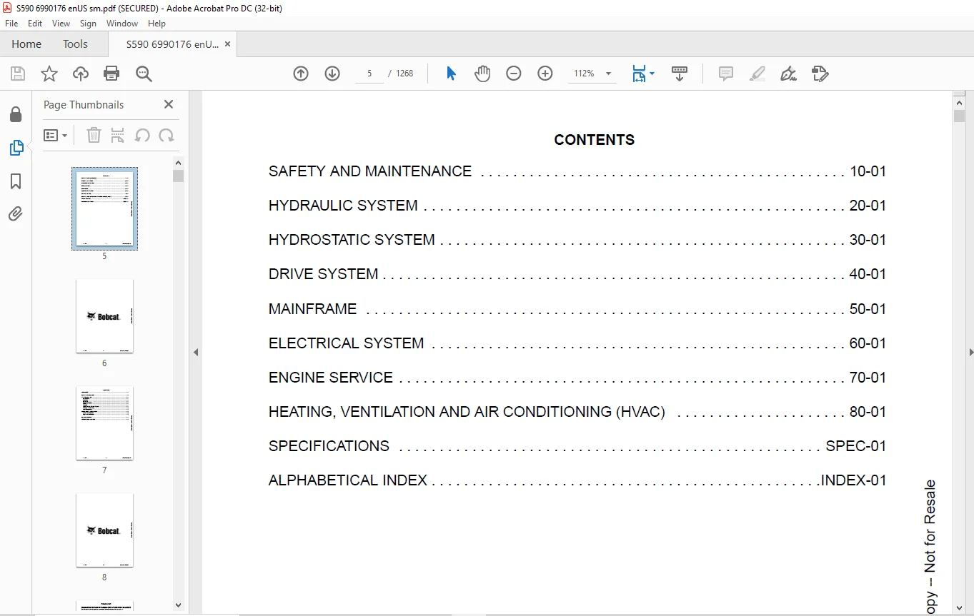
TABLE OF CONTENTS:
Bobcat S590 Skid-Steer Loader Service Manual 6990176 – PDF DOWNLOAD
MAINTENANCE SAFETY 3
CONTENTS 5
FOREWORD 7
FOREWORD 9
SAFETY INSTRUCTIONS 11
FIRE PREVENTION 13
Maintenance 13
Operation 13
Electrical 13
Hydraulic System 13
Fueling 13
Starting 13
Spark Arrester Exhaust System 13
Welding And Grinding 14
Fire Extinguishers 14
SERIAL NUMBER LOCATIONS 15
Loader Serial Number 15
Engine Serial Number 15
DELIVERY REPORT 16
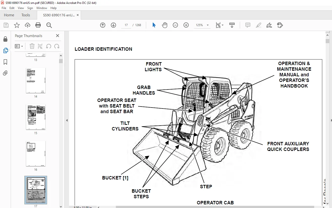
LOADER IDENTIFICATION 17
SAFETY AND MAINTENANCE 19
LIFTING AND BLOCKING THE LOADER 23
Procedure 23
LIFT ARM SUPPORT DEVICE 25
Description 25
Installing 26
Removing 27
OPERATOR CAB 29
Description 29
Raising 30
Lowering 31
Cab Door Sensor 32
Special Applications Kit 32
Special Applications Kit Inspection And Maintenance 32
Forestry Door And Window Kit 33
Forestry Door And Window Kit Inspection And Maintenance 33
TRANSPORTING THE LOADER ON A TRAILER 35
Loading And Unloading 35
Fastening 35
TOWING THE LOADER 37
Procedure 37
REMOTE START TOOL KIT – MEL1563 39
Remote Start Tool – MEL1563 39
Service Tool Harness Communicator – MEL1566 41
Remote Start Procedure 41
REMOTE START TOOL (SERVICE TOOL) KIT – 7217666 45
Description 45
Remote Start Tool (Service Tool) – 7022042 46
Loader Service Tool Harness – 6689747 47
Computer Service Tool Harness – 6689746 48
Remote Start Procedure 49
SERVICE SCHEDULE 53
Maintenance Intervals 53
ENGINE AIR CLEANER 55
Replacing Filters 55
ENGINE COOLING SYSTEM (EARLIER MODELS) 57
Maintenance Platform 57
Cooling System Identification 57
Cleaning 58
Checking And Adding Coolant 60
Removing And Replacing Coolant 61
ENGINE COOLING SYSTEM (LATER MODELS) 63
Maintenance Platform 63
Cleaning 63
Checking And Adding Coolant 65
Removing And Replacing Coolant 66
FUEL SYSTEM 69
Fuel Specifications 69
Biodiesel Blend Fuel 69
Filling The Fuel Tank 70
Fuel Filter 71
Removing Air From The Fuel System 72
ENGINE LUBRICATION SYSTEM 73
Checking And Adding Engine Oil 73
Engine Oil Chart 73
Removing And Replacing Oil And Filter 74
HYDRAULIC / HYDROSTATIC SYSTEM (EARLIER MODELS) 75
Checking And Adding Fluid 75
Hydraulic / Hydrostatic Fluid Chart 75
Removing And Replacing Hydraulic Fluid 76
Removing And Replacing Hydraulic / Hydrostatic Filter 78
Removing And Replacing Hydraulic Charge Filter 79
Replacing Reservoir Breather Cap 80
HYDRAULIC / HYDROSTATIC SYSTEM (LATER MODELS) 81
Checking And Adding Fluid 81
Hydraulic / Hydrostatic Fluid Chart 81
Removing And Replacing Hydraulic Fluid 82
Removing And Replacing Hydraulic / Hydrostatic Filter 84
Removing And Replacing Hydraulic Charge Filter 85
Replacing Reservoir Breather Cap 86
FINAL DRIVE TRANSMISSION (CHAINCASE) 87
Checking And Adding Fluid 87
Removing And Replacing Fluid 87
BOB-TACH (HAND LEVER) 89
Inspection And Maintenance 89
BOB-TACH (POWER) 91
Inspection And Maintenance 91
LUBRICATING THE LOADER 93
Lubrication Locations 93
TIRE MAINTENANCE 97
Wheel Nuts 97
Rotating 97
Mounting 98
SPARK ARRESTER MUFFLER 99
Cleaning Procedure 99
PIVOT PINS 101
Inspection And Maintenance 101
LOADER STORAGE AND RETURN TO SERVICE 103
Storage 103
Return To Service 103
STOPPING THE ENGINE AND LEAVING THE LOADER 105
Procedure 105
EMERGENCY EXIT 107
Rear Window Identification 107
Rear Window Removal (Latches) 107
Rear Window Removal (Rubber Cord) 107
External Access (Rear Window With Latches) 108
External Access (Rear Window With Rubber Cord) 108
Front Door 108
SEAT BELT 111
Inspection And Maintenance 111
HYDRAULIC SYSTEM 113
HYDRAULIC/HYDROSTATIC SCHEMATIC 119
HYDRAULIC SYSTEM INFORMATION 135
Glossary Of Hydraulic / Hydrostatic Symbols 135
Troubleshooting 139
CYLINDER (LIFT) 141
Testing 141
Removal And Installation 142
Parts Identification 146
Disassembly 147
Assembly 149
CYLINDER (TILT) 153
Testing 153
Removal And Installation 154
Base End Pivot Pin Removal And Installation 155
Parts Identification 156
Disassembly 157
Assembly 159
CYLINDER (LIFT) (S/N AZND11152 & ABOVE) 163
Testing 163
Removal And Installation 164
Parts Identification 168
Disassembly 169
Assembly 171
CYLINDER (TILT) (S/N AZND11152 & ABOVE) 175
Testing 175
Removal And Installation 176
Base End Pivot Pin Removal And Installation 177
Parts Identification 178
Disassembly 179
Assembly 181
CYLINDER (BOB-TACH) 185
Testing 185
Removal And Installation 186
Parts Identification 187
Disassembly 188
Assembly 190
MAIN RELIEF VALVE 193
Description 193
Testing 194
Adjusting 196
Removal And Installation 197
HYDRAULIC CONTROL VALVE (STANDARD) 199
Description 199
Removal And Installation 200
Mount Bracket Removal And Installation 203
Identification Chart 204
Lift Load Check Valve Removal And Installation 205
Load Check Valve Removal And Installation (Tilt And Auxiliary) 206
Anti-Cavitation Valve Removal And Installation (Lift, Rod End) 207
Port Relief / Anti-Cavitation Valve Removal And Installation (Lift, Base End) 207
Port Relief / Anti-Cavitation Valve Removal And Installation (Tilt, Base End) 208
Port Relief / Anti-Cavitation Valve Removal And Installation (Tilt, Rod End) 208
Port Relief Valve Removal And Installation 209
Plug Removal And Installation 211
Rubber Boot Removal And Installation 212
End Cap Block Removal And Installation 212
Lift Spool And Detent Removal And Installation 213
Tilt Spool Removal And Installation 221
Auxiliary Spool Removal And Installation 223
Auxiliary Solenoid Removal And Installation 224
Solenoid Removal And Installation 225
Lock Valve Removal And Installation 226
Lift Arm Bypass Orifice Removal And Installation 228
Main Relief Valve Removal And Installation 228
Check Valve Removal And Installation 229
HYDRAULIC CONTROL VALVE (ACS) OR (SJC) 231
Description 231
Removal And Installation 231
Actuator Removal And Installation (In Loader) 235
Actuator Removal And Installation (Out Of Loader) 237
Identification Chart 240
Mount Bracket Removal And Installation 241
Lift Load Check Valve Removal And Installation 241
Load Check Valve Removal And Installation (Tilt And Auxiliary) 242
Anti-Cavitation Valve Removal And Installation (Lift, Rod End) 243
Port Relief / Anti-Cavitation Valve Removal And Installation (Lift, Base End) 243
Port Relief / Anti-Cavitation Valve Removal And Installation (Tilt, Base End) 244
Port Relief / Anti-Cavitation Valve Removal And Installation (Tilt, Rod End) 244
Port Relief Valve Removal And Installation 245
Plug Removal And Installation 247
End Cap Block Removal And Installation 248
Lift Spool Removal And Installation 248
Lift Spool Disassembly And Assembly 250
Tilt Spool Removal And Installation 251
Auxiliary Spool Removal And Installation 253
Auxiliary Solenoid Removal And Installation 254
Solenoid Removal And Installation 255
Lock Valve Removal And Installation 256
Lift Arm Bypass Orifice Removal And Installation 258
Main Relief Valve Removal And Installation 258
Check Valve Removal And Installation 259
LIFT ARM BYPASS CONTROL VALVE 261
Description 261
Testing 261
Removal And Installation 262
Bracket Removal And Installation 263
Disassembly And Assembly 263
HYDRAULIC PUMP 265
Description 265
Pump Test At Quick Couplers 266
Direct Pump Test (Standard Section) 268
Direct Pump Test (Charge Section) 270
Removal And Installation 272
Hydraulic Pump Startup 274
Parts Identification 275
Disassembly And Assembly 276
HYDRAULIC PUMP (HIGH FLOW) 277
Description 277
Pump Test At Quick Couplers 278
Direct Pump Test (Standard Section) 280
Direct Pump Test (Charge Section) 281
Direct Pump Test (High Flow Section) 283
High Flow Relief Valve Adjustment 285
High Flow Relief Valve Removal And Installation 287
Solenoid Removal And Installation 288
Removal And Installation 289
Hydraulic Pump Startup 291
Parts Identification 292
Disassembly And Assembly 293
HYDRAULIC / HYDROSTATIC FILTERS 295
Description 295
Housing Removal And Installation 295
HYDRAULIC FLUID RESERVOIR 297
Description 297
Removal And Installation 297
Hydraulic Fluid Screen 298
OIL COOLER (EARLIER MODELS) 299
Description 299
Removal And Installation 299
OIL COOLER (LATER MODLES) 301
Removal And Installation 301
BUCKET POSITION VALVE 303
Description 303
Solenoid Removal And Installation 303
Solenoid Testing 304
Removal And Installation 305
Disassembly And Assembly 307
REAR AUXILIARY DIVERTER VALVE 309
Description 309
Solenoid Testing 309
Removal And Installation 310
Disassembly And Assembly 311
BOB-TACH (POWER) BLOCK (S/N ANMN11001 – ANMN15407) 317
Description 317
Removal And Installation 317
Disassembly And Assembly 319
BOB-TACH (POWER) BLOCK (S/N ANMN15408 & ABOVE) 327
Description 327
Testing Relief Valve 328
Removal And Installation 330
Disassembly And Assembly 332
FRONT AUXILIARY HYDRAULIC COUPLER BLOCK 337
Description 337
Removal And Installation 338
Disassembly And Assembly (FFI/FI) 338
Disassembly And Assembly (FFH/FH) 340
AUTOMATIC RIDE CONTROL 343
Description 343
Removal And Installation 344
Checking The Pressure In The Accumulator 347
Adding Nitrogen To The Accumulator 349
HYDROSTATIC SYSTEM 351
HYDROSTATIC SYSTEM INFORMATION 353
Description 353
Troubleshooting 354
HYDROSTATIC DRIVE MOTOR 355
Description 355
Removal And Installation 355
Parts Identification 358
Disassembly And Assembly 359
HYDROSTATIC DRIVE MOTOR (TWO-SPEED) 365
Description 365
Removal And Installation (Left Side) 366
Removal And Installation (Right Side) 369
Parts Identification 372
Disassembly 373
Assembly 386
HYDROSTATIC MOTOR CARRIER 401
Description 401
Shaft Seal Removal And Installation 402
Removal And Installation 404
Parts Identification 406
Disassembly 407
Assembly 409
HYDROSTATIC MOTOR CARRIER (TWO-SPEED) 413
Description 413
Shaft Seal Removal And Installation 414
Removal And Installation 416
Parts Identification 418
Disassembly 419
Assembly 421
CHARGE PRESSURE 425
Description 425
Testing 426
Adjusting 428
Sender Removal And Installation 430
HYDROSTATIC PUMP 431
Description 431
Removal And Installation 432
Hydrostatic Pump Startup 433
Replenishing / High Pressure Relief Valve Removal And Installation 434
Parts Identification (Left Half) 435
Parts Identification (Right Half) 436
Disassembly 437
Assembly 444
HYDROSTATIC PUMP (SJC) 451
Description 451
Hydraulic Controller Removal And Installation 452
Removal And Installation 454
Hydrostatic Pump Startup 456
Parts Identification 457
High Pressure Relief And Bypass Valve 458
Charge Relief Valve 459
Disassembly And Assembly 460
Mechanical Neutral Adjustment 473
Hydraulic Controller Neutral Adjustment 476
HYDROSTATIC PUMP (SJC) (S/N ANMN17101 & ABOVE) 479
Description 479
Port Locations And Gauge Installation 480
Removal And Installation 481
Hydrostatic Pump Startup 483
Parts Identification 484
High Pressure Relief And Bypass Valve 487
Charge Pressure Relief Valve 488
Disassembly And Assembly 489
Mechanical Neutral Adjustment 501
Hydraulic Controller Neutral Adjustment 503
DRIVE BELT 505
Belt Adjustment 505
Belt Replacement 506
TWO-SPEED 509
Valve Block Removal And Installation 509
Valve Block Disassembly And Assembly 510
DRAIN MANIFOLD 511
Description 511
Drain Manifold Removal And Installation 511
DRIVE SYSTEM 513
BRAKE 515
Description 515
Disc Removal And Installation 515
DRIVE COMPONENTS 517
Description 517
Axle Seal Removal And Installation 518
Axle, Sprocket And Bearings Removal And Installation 520
Chain Removal And Installation 525
CHAINCASE 527
Description 527
Front Cover Removal And Installation 527
Center Cover Removal And Installation 528
Rear Cover Removal And Installation 529
MAINFRAME 531
SEAT BAR 535
Description 535
Removal And Installation 535
Disassembly And Assembly 536
Compression Spring Disassembly And Assembly 537
OPERATOR CAB 539
Gas Spring Removal And Installation 539
Gas Spring Bracket Disassembly And Assembly 540
Removal And Installation 540
OPERATOR SEAT 543
Removal And Installation 543
Seat Belt Removal And Installation (Retractable) 543
Seat Belt And Bracket Removal And Installation (Standard) 544
Seat Belt Bracket Removal And Installation 544
OPERATOR SEAT (SUSPENSION) 545
Removal And Installation 545
Slide Rail Removal And Installation 545
Seat Belt Removal And Installation 546
Lower Cushion Removal 546
Lower Cushion Installation 547
Back Cushion Removal And Installation 547
Shock Removal And Installation 548
3-Point Seat Belt Removal And Installation 548
BOB-TACH (HAND LEVER) 551
Description 551
Removal And Installation 551
Lever And Wedge Disassembly And Assembly 553
Pivot Pin Bushing And Seal Removal And Installation 555
BOB-TACH (POWER) 557
Description 557
Removal And Installation 557
Lever And Wedge Disassembly And Assembly 560
Pivot Pin Bushing And Seal Removal And Installation 562
LIFT ARMS 563
Stabilizer Bar Removal And Installation 563
Link Removal And Installation 564
Removal And Installation 565
REAR GRILLE 569
Removing 569
Installing 569
REAR DOOR (TAILGATE) 571
Removal And Installation 571
Striker Removal And Installation 572
Striker Disassembly And Assembly 572
Striker Adjusting 573
Latch Removal And Installation 573
FUEL TANK 575
Removal And Installation 575
Fuel Level Sender Removal And Installation 578
Fuel Fill Screen Removal And Installation 578
CONTROL PEDALS AND LINKAGES 579
Description 579
Pedal Removal And Installation 579
Linkage Removal And Installation 580
Pedal (Adjusting) 581
Floor Pan Removal And Installation 582
CONTROL PEDALS AND LINKAGES (ACS) 583
Description 583
Pedal Removal And Installation 583
Linkage Removal And Installation 584
Pedal (Adjusting) 584
Floor Pan Removal And Installation 585
CONTROL PANEL 587
Description 587
Removal And Installation 588
Disassembly And Assembly 589
Linkage Removal And Installation 593
Pintle Arm Disassembly And Assembly 597
Linkage Neutral (Adjusting) 598
Linkage Travel (Adjusting) 602
Shock Removal And Installation 606
CONTROL PANEL (SJC) 607
Description 607
Removal And Installation 607
CONTROL HANDLE / LEVER 609
Description 609
Lever Removal And Installation 609
Boot Removal And Installation 610
CONTROL HANDLE / LEVER (ACS) 611
Description 611
Handle Sensor Removal And Installation 611
Handle Removal And Installation 614
Handle Disassembly And Assembly 615
Lever Removal And Installation 615
Boot Removal And Installation 616
CONTROL HANDLE / LEVER (SJC) 617
Description 617
Joystick Testing 617
Joystick Removal And Installation 618
ACCESS PANEL (INSIDE) 619
Removal And Installation (Left) 619
Removal And Installation (Right) 619
ACCESS PANEL (INSIDE) (SJC) 621
Removal And Installation (Left) 621
Removal And Installation (Right) 621
WINDOW (REAR) 623
Rear Window Identification 623
Rear Window Removal (Latches) 623
Rear Window Removal (Rubber Cord) 623
Disassembly And Assembly 624
External Access (Rear Window With Latches) 625
External Access (Rear Window With Rubber Cord) 625
WINDOW (TOP) 627
Removal And Installation 627
WINDOW (SIDE) 629
Removal And Installation 629
CAB DOOR 631
Description 631
Removal And Installation 631
Disassembly And Assembly 632
Aligning 633
Adjusting 634
Checking Operation 634
ARMREST 635
Description 635
Removal And Installation 636
Disassembly And Assembly 637
LEFT SIDE LOWER PANEL 639
Removal And Installation 639
Disassembly And Assembly 641
RIGHT SIDE LOWER PANEL 643
Removal And Installation 643
Disassembly And Assembly 644
HEADLINER 647
Removal And Installation 647
ELECTRICAL SYSTEM 649
ELECTRICAL SCHEMATIC 655
ELECTRICAL SYSTEM INFORMATION 865
Glossary Of Electrical Symbols 865
Standard Cab Harness Connectors 868
Deluxe Cab Harness Connectors 869
Mainframe Harness Connectors – Manual Controls 870
Mainframe Harness Connectors – SJC 871
Description 872
Troubleshooting 873
Fuse And Relay Location / Identification 874
Solenoid Testing 876
BATTERY 877
Removal And Installation 877
Battery Maintenance 878
Maintaining Battery Charge Level 878
Battery Service During Machine Storage 878
Battery Testing 879
Battery Charging 879
Using A Booster Battery (Jump Starting) 880
ALTERNATOR 881
Belt Adjustment 881
Belt Replacement 881
Alternator Voltage Testing 882
Low Voltage Testing 882
High Voltage Testing 883
Removal And Installation 884
Parts Identification 885
STARTER 887
Testing 887
Removal And Installation 887
Parts Identification 888
INSTRUMENT PANELS 889
Left Panel 889
Display Screen 891
Right Panel (Standard Key Panel) 892
Right Panel (Keyless Start Panel) 893
Right Panel (Deluxe Instrumentation Panel) 894
Left Switch Panel 896
Right Switch Panel 896
Left Side Lower Panel 897
Right Side Lower Panel 897
Left Panel Removal And Installation 898
Right Panel (Standard Key Panel) Removal And Installation 898
Right Panel (Keyless Start Panel) Removal And Installation 899
Right Panel (Deluxe Instrumentation Panel) Removal And Installation 899
Key Switch Disassembly And Assembly 900
Alarm Disassembly And Assembly 900
Left Switch Panel Removal And Installation 901
Right Switch Panel Removal And Installation 901
LIGHTS 903
Front Removal And Installation 903
Rear Removal And Installation 904
Cab Light Removal And Installation 904
BOBCAT CONTROLLERS (GATEWAY AND AUXILIARY) 905
Description 905
Connector Identification 906
Removal And Installation 912
BOBCAT CONTROLLER (ACS) 913
Description 913
Connector And Wire Identification 914
Removal And Installation 915
BOBCAT CONTROLLER (SJC) (DRIVE) 917
Description 917
Connector Identification 918
Removal And Installation 920
DIAGNOSTIC SERVICE CODES 921
Viewing Service Codes 921
Service Codes List 922
BOBCAT INTERLOCK CONTROL SYSTEM (BICS™) 929
Description 929
Inspecting The BICS™ (Engine STOPPED – Key ON) 930
Inspecting Deactivation Of The Auxiliary Hydraulics System (Engine STOPPED – Key ON) 930
Inspecting The Seat Bar Sensor (Engine RUNNING) 930
Inspecting The Traction Lock And Parking Brake (Engine RUNNING) 930
Inspecting The Lift Arm Bypass Control 930
Inspecting Deactivation Of Lift And Tilt Functions (ACS And SJC) 930
Troubleshooting 931
SEAT BAR SENSOR 933
Description 933
Troubleshooting 933
Testing 934
Removal 935
Installation 937
Bobcat Interlock Control System (BICS™) Circuit Test 938
TRACTION LOCK 941
Description 941
Troubleshooting 942
Inspecting 943
CONTROL SYSTEM (ACS) 945
Description 945
Troubleshooting 946
Handle Sensor Connector Disassembly And Assembly 947
Switch Handle Removal 948
Switch Handle Installation 950
Actuator Connector Disassembly And Assembly 953
Handle Lock Solenoid Removal And Installation 954
Handle Lock Solenoid Disassembly And Assembly 954
Foot Sensor Removal And Installation 955
Foot Sensor Disassembly And Assembly 956
Foot Sensor Lock Solenoid Removal And Installation 956
ELECTRICAL / HYDRAULIC CONTROLS 957
Identification Chart 957
Description 958
Identification Chart ACD Group 0 959
Identification Chart ACD Group 1 960
Identification Chart ACD Group 2 961
Identification Chart ACD Group 3 962
ELECTRICAL / HYDRAULIC CONTROLS (ACS) 963
Identification Chart 963
Description 964
Identification Chart ACD Group 0 965
Identification Chart ACD Group 1 966
Identification Chart ACD Group 2 967
Identification Chart ACD Group 3 968
ELECTRICAL / HYDRAULIC CONTROLS (SJC) 969
Identification Chart 969
Description 970
Identification Chart ACD Group 0 971
Identification Chart ACD Group 1 972
Identification Chart ACD Group 2 973
Identification Chart ACD Group 3 974
SERVICE PC (LAPTOP COMPUTER) 975
Connecting Remote Start Tool 975
Connecting Remote Start Tool (Service Tool) 975
CALIBRATION 977
Description 977
Actuator Testing 977
Lift And Tilt Calibration (SJC) 980
Hydrostatic Pump Calibration (SJC) 982
Lift And Tilt Calibration (ACS) 987
STEERING DRIFT COMPENSATION (OPERATOR MODE) 989
Description 989
Operation 989
STEERING DRIFT COMPENSATION (SERVICE MODE) 991
Description 991
Operation 991
FLYWHEEL RPM SENSOR 993
Description 993
Removal 993
Installation 994
CONTROL PANEL SETUP 995
Right Panel Setup (Deluxe Instrumentation Panel) 995
PASSWORD SETUP (DELUXE INSTRUMENTATION PANEL) 999
Password Description 999
Changing The Owner Password 999
Changing The User Passwords 1000
Password Lockout Feature 1000
PASSWORD SETUP (KEYLESS START PANEL) 1001
Password Description 1001
Changing The Owner Password 1001
Password Lockout Feature 1001
MAINTENANCE CLOCK 1003
Description 1003
Setup 1004
Reset 1007
BACK-UP ALARM SYSTEM 1009
Description 1009
Inspection 1009
Adjusting Switch Position 1010
Troubleshooting (Standard And ACS) 1011
Troubleshooting (Joystick) 1012
Alarm Removal And Installation 1013
Switch Removal And Installation 1013
FRONT HORN 1015
Removal And Installation 1015
Troubleshooting 1016
Troubleshooting (Joystick) 1017
TELEMATICS 1019
Description 1019
Removal And Installation 1019
Procedure 1020
ENGINE SERVICE 1021
ENGINE INFORMATION 1025
Description 1025
Specifications 1026
Torque Values 1029
Troubleshooting 1029
Engine Removal And Installation 1031
Engine Mount Replacement 1039
Compression – Testing 1040
ENGINE SPEED CONTROL (HAND) 1043
Removal And Installation 1043
Disassembly And Assembly 1043
Cable Removal And Installation 1044
ENGINE SPEED CONTROL (FOOT) 1045
Removal And Installation 1045
Disassembly And Assembly 1046
MUFFLER 1049
Removal And Installation 1049
AIR CLEANER 1051
Housing Removal And Installation 1051
ENGINE COOLING SYSTEM (EARLIER MODELS) 1053
Radiator Removal And Installation 1053
Hydraulic Fan Description 1055
Fan Duct Removal And Installation 1055
Hydraulic Fan Motor Assembly Removal And Installation 1056
Hydraulic Fan Motor Removal And Installation 1057
Hydraulic Fan Motor Disassembly And Assembly 1059
Blower Housing Removal And Installation 1060
Water Pump Removal And Installation 1061
Water Pump Disassembly And Assembly 1061
Thermostat Housing Removal And Installation 1062
Thermostat – Testing 1063
ENGINE COOLING SYSTEM (LATER MODELS) 1065
Radiator / Oil Cooler Removal And Installation 1065
Hydraulic Fan Description 1068
Reversible Hydraulic Fan Description 1068
Fan Duct Removal And Installation 1068
Hydraulic Fan Motor Assembly Removal And Installation 1069
Hydraulic Fan Motor Removal And Installation 1070
Hydraulic Fan Motor Disassembly And Assembly 1072
Blower Housing Removal And Installation 1080
Water Pump Removal And Installation 1081
Water Pump Disassembly And Assembly 1081
Thermostat Housing Removal And Installation 1082
Thermostat – Testing 1083
LUBRICATION SYSTEM 1085
Oil Pan Removal And Installation 1085
Oil Pump Removal And Installation 1085
Relief Valve – Testing 1086
Oil Pump Inspection 1086
Oil Filter Cooler Removal And Installation 1087
Engine Oil Pressure – Testing 1088
FUEL SYSTEM 1089
Fuel Shutoff Solenoid – Testing 1089
Fuel Shutoff Solenoid Removal And Installation 1089
Fuel Injection Pump – Testing 1090
Fuel Injection Pump Assembly Removal And Installation 1091
Governor Housing Disassembly And Assembly 1094
Governor Disassembly And Assembly 1096
Fuel Camshaft Removal And Installation 1098
Fuel Injection Pump Removal And Installation 1101
Fuel Injection Pump – Timing 1103
Fuel Injector Removal And Installation 1105
Fuel Injector Nozzle Pressure – Testing 1106
Nozzle Spray Condition 1107
Valve Seat Tightness 1107
CYLINDER HEAD 1109
Glow Plugs – Testing 1109
Glow Plugs Removal And Installation 1109
Valve Clearance Adjustment 1110
Valve Timing – Inspecting 1111
Cylinder Head Removal And Installation 1112
Cylinder Head Disassembly And Assembly 1115
Cylinder Head – Servicing 1116
Cylinder Head Top Clearance 1117
Valve Guide – Inspecting 1118
Valve Guide Removal And Installation 1118
Reconditioning The Valve And Valve Seat 1119
Valve Spring 1121
Valve Tappets 1122
Rocker Arm And Shaft – Inspecting 1123
Bridge Arm And Bridge Arm Shaft – Inspecting 1123
Bridge Arm Shaft – Removal And Installation 1124
Push Rod Alignment – Inspecting 1125
CRANKSHAFT AND PISTONS 1127
Piston And Connecting Rod Removal And Installation 1127
Piston And Connecting Rod – Servicing 1128
Cylinder Bore – Inspecting 1131
Connecting Rod Alignment 1131
Crankshaft Gear Removal And Installation 1132
Crankshaft And Bearings Removal And Installation 1132
Crankshaft And Bearings – Servicing 1134
CAMSHAFT AND TIMING GEARS 1139
Timing Gearcase Cover Removal 1139
Timing Gearcase Cover Installation 1140
Timing Gears Backlash – Inspection 1143
Idler Gear And Camshaft Removal And Installation 1143
Camshaft – Servicing 1144
Idler Gear And Shaft – Servicing 1145
TURBOCHARGER 1147
Description 1147
Testing 1147
Removal And Installation 1148
FLYWHEEL AND HOUSING 1149
Flywheel Removal And Installation 1149
Ring Gear Removal And Installation 1150
Housing Removal And Installation 1151
EXHAUST GAS RECIRCULATION (EGR) SYSTEM 1153
Description 1153
Testing 1154
Removal And Installation 1157
Disassembly And Assembly 1158
HEATING, VENTILATION AND AIR CONDITIONING (HVAC) 1159
AIR CONDITIONING SYSTEM FLOW 1161
Description 1161
Chart 1162
Components 1163
Safety Equipment 1166
REGULAR MAINTENANCE 1167
Filters 1167
Belt Adjustment 1168
Belt Replacement 1168
Air Conditioning Condenser 1168
Air Conditioning Lubrication 1168
Air Conditioning Service Chart 1169
Evaporator / Heater Coil 1170
TROUBLESHOOTING 1173
Blower Motor Does Not Operate 1173
Blower Motor Operates Normally, But Air Flow Is Insufficient 1173
Insufficient Cooling Although Air Flow And Compressor Operation Are Normal 1173
The Compressor Does Not Operate At All, Or Operates Improperly 1173
Gauge Pressure Related Troubleshooting 1174
Troubleshooting Tree 1176
Temperature / Pressure Chart 1180
Poor A/C Performance 1182
HVAC Repair And Leaks 1183
Electrical System 1184
Engine Coolant Bypassing The Heater Valve 1190
Heater Valve Not Opening Or Closing 1191
SYSTEM CHARGING AND RECLAMATION 1193
Refrigerant Identification 1193
Reclamation And Charging With Recovery / Charging Unit 1194
COMPRESSOR 1197
Removal And Installation 1197
Oil 1198
Oil Check 1199
CONDENSER (EARLIER MODELS) 1201
Removal And Installation 1201
CONDENSER (LATER MODELS) 1203
Removal And Installation 1203
RECEIVER / DRIER (EARLIER MODELS) 1205
Receiver / Drier Removal And Installation 1205
Pressure Relief Valve Removal And Installation 1206
Pressure Switch Removal And Installation 1207
Schrader® Valve Removal And Installation 1208
RECEIVER / DRIER (LATER MODELS) 1209
Receiver / Drier Removal And Installation 1209
Pressure Switch Removal And Installation 1211
Schrader® Valve Removal And Installation 1212
EVAPORATOR / HEATER UNIT 1213
Removal And Installation 1213
THERMOSTAT 1215
Description 1215
Removal And Installation 1216
EXPANSION VALVE 1217
Removal And Installation 1217
EVAPORATOR COIL 1219
Removal And Installation 1219
HEATER COIL 1221
Removal And Installation 1221
BLOWER FAN 1223
Removal And Installation 1223
Disassembly And Assembly 1224
HEATER VALVE 1227
Removal And Installation 1227
EVAPORATOR / HEATER COVER 1229
Removing 1229
Installing 1229
SPECIFICATIONS 1231
(S590) LOADER SPECIFICATIONS 1233
Machine Dimensions 1233
Performance 1234
Engine 1234
Drive System 1235
Controls 1235
Hydraulic System 1236
Electrical System 1237
Capacities 1237
Tires 1238
TECHNICAL SERVICE GUIDE SPECIFICATIONS 1239
Engine 1239
Engine Torques 1239
Cooling System 1239
Loader Torques 1240
Hydraulic / Hydrostatic System 1240
Fuel Consumption 1240
TORQUE SPECIFICATIONS FOR BOLTS 1241
Torque For General SAE Bolts 1241
Torque For General Metric Bolts 1242
HYDRAULIC CONNECTION SPECIFICATIONS 1243
Straight Thread O-ring Fitting 1243
Flare Fitting 1244
Tubelines And Hoses 1244
HYDRAULIC / HYDROSTATIC FLUID SPECIFICATIONS 1245
Specifications 1245
CONVERSIONS 1247
Decimal And Millimeter Equivalent Chart 1247
U S To Metric Conversion Chart 1247
SERVICE TOOLS REQUIRED 1249
Remote Start Tools 1249
Hydraulic Tools 1250
Mainframe And Drive Tools 1253
Electrical Tools 1256
Engine Tools 1257
HVAC Tools 1262
ALPHABETICAL INDEX 1263
IMAGES PREVIEW OF THE MANUAL:
Contact us: [email protected]
https://vimeo.com/843844884?share=copy
PLEASE NOTE:
- This is the SAME manual used by the dealers to troubleshoot any faults in your vehicle. This can be yours in 2 minutes after the payment is made.
- Contact us at [email protected] should you have any queries before your purchase or that you need any other service / repair / parts operators manual.
S.V