Bobcat S590 Skid-Steer Loader Service Manual 6990685 – PDF DOWNLOAD
$36.95
Bobcat S590 Skid-Steer Loader Service Manual 6990685 – PDF DOWNLOAD
S/N AR9R11001 & Above
S/N B3H111001 & Above
S/N B4TP11001 & Above
Description
Bobcat S590 Skid-Steer Loader Service Manual 6990685 – PDF DOWNLOAD
FILE DETAILS:
Bobcat S590 Skid-Steer Loader Service Manual 6990685 – PDF DOWNLOAD
Language : English
Pages : 1322
Downloadable : Yes
File Type : PDF
DESCRIPTION:
Bobcat S590 Skid-Steer Loader Service Manual 6990685 – PDF DOWNLOAD
FOREWORD:
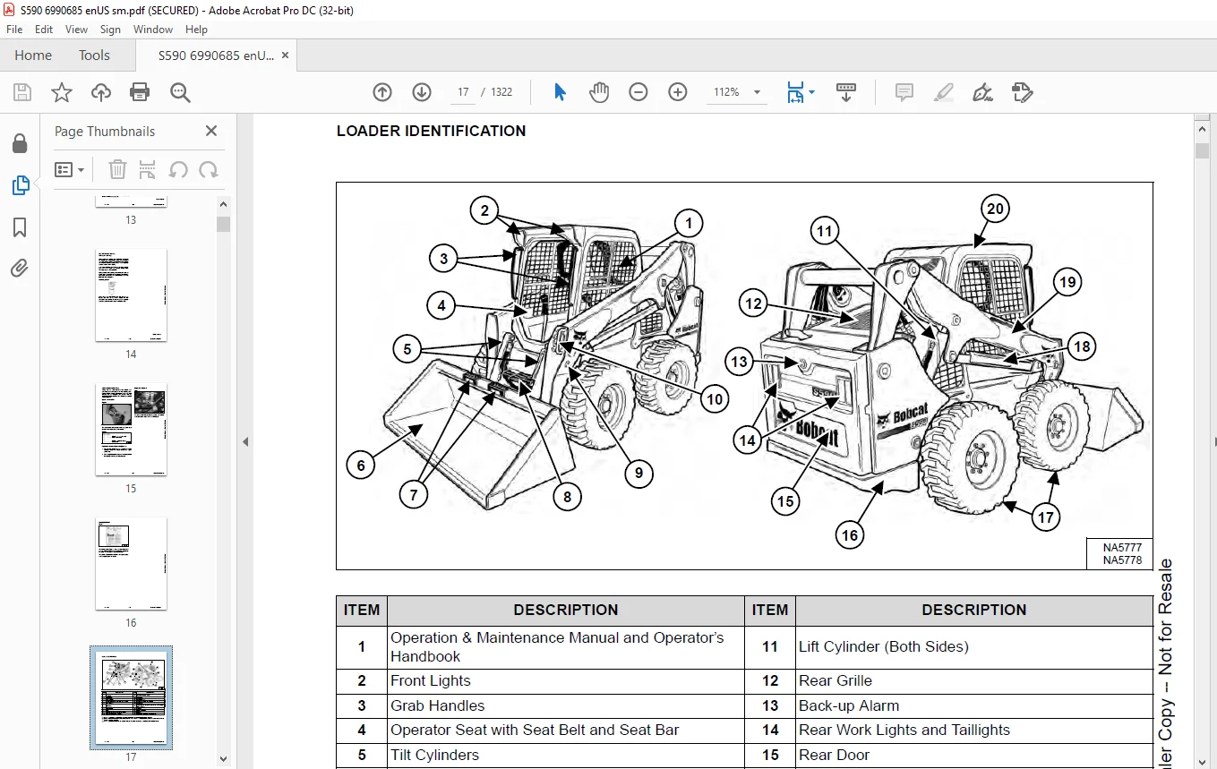
This manual is for the Bobcat loader mechanic. It provides necessary servicing and adjustment procedures for the Bobcat loader and its component parts and systems. Refer to the Operation & Maintenance Manual for operating instructions, starting procedure, daily checks, etc.
A general inspection of the following items must be made after the loader has had service or repair:
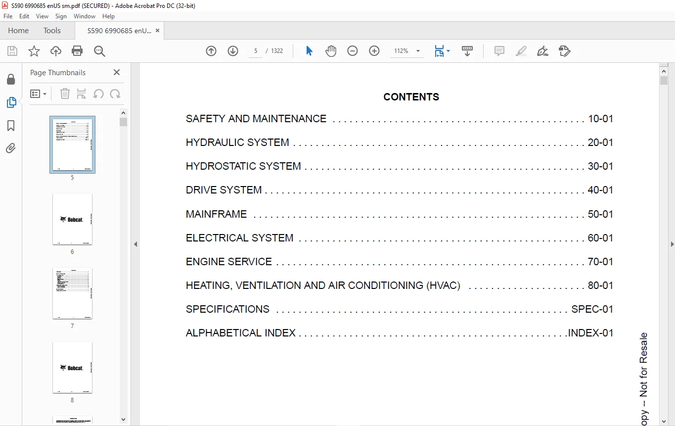
TABLE OF CONTENTS:
Bobcat S590 Skid-Steer Loader Service Manual 6990685 – PDF DOWNLOAD
MAINTENANCE SAFETY 3
CONTENTS 5
FOREWORD 7
FOREWORD 9
SAFETY INSTRUCTIONS 11
FIRE PREVENTION 13
Maintenance 13
Operation 13
Electrical 13
Hydraulic System 13
Fueling 13
Starting 13
Spark Arrester Exhaust System 13
Welding And Grinding 14
Fire Extinguishers 14
SERIAL NUMBER LOCATIONS 15
Loader Serial Number 15
Engine Serial Number 15
DELIVERY REPORT 16
LOADER IDENTIFICATION 17
SAFETY AND MAINTENANCE 19
LIFTING AND BLOCKING THE LOADER 23
Procedure 23
LIFT ARM SUPPORT 25
Description 25
Installing 26
Removing 27
OPERATOR CAB 29
Description 29
Cab Door Sensor 29
Raising 30
Lowering 31
Special Applications Kit 32
Special Applications Kit Inspection And Maintenance 32
Forestry Door And Window Kit 33
Forestry Door And Window Kit Inspection And Maintenance 33
TRANSPORTING THE LOADER ON A TRAILER 35
Loading And Unloading 35
Fastening 35
TOWING THE LOADER 37
Procedure 37
REMOTE START TOOL KIT – MEL1563 39
Remote Start Tool – MEL1563 39
Service Tool Harness Communicator – MEL1566 41
Remote Start Procedure 41
REMOTE START TOOL (SERVICE TOOL) KIT – 7217666 45
Description 45
Remote Start Tool (Service Tool) – 7022042 46
Loader Service Tool Harness – 6689747 47
Computer Service Tool Harness – 6689746 48
Remote Start Procedure 49
SERVICE SCHEDULE 53
Maintenance Intervals 53
ENGINE AIR CLEANER 55
Replacing Filters 55
ENGINE COOLING SYSTEM 57
Maintenance Platform 57
Cleaning 57
Checking And Adding Coolant 60
Removing And Replacing Coolant 61
FUEL SYSTEM 63
Fuel Specifications 63
Biodiesel Blend Fuel 63
Filling The Fuel Tank 64
Fuel Filter 65
Removing Air From The Fuel System 67
ENGINE LUBRICATION SYSTEM 69
Checking And Adding Engine Oil 69
Engine Oil Chart 69
Removing And Replacing Oil And Filter 70
HYDRAULIC / HYDROSTATIC SYSTEM 73
Checking And Adding Fluid 73
Hydraulic / Hydrostatic Fluid Chart 73
Removing And Replacing Hydraulic Fluid 74
Removing And Replacing Hydraulic / Hydrostatic Filter 76
Removing And Replacing Hydraulic Charge Filter 77
Replacing Reservoir Breather Cap 79
FINAL DRIVE TRANSMISSION (CHAINCASE) 81
Checking And Adding Fluid 81
Removing And Replacing Fluid 81
BOB-TACH (HAND LEVER) 83
Inspection And Maintenance 83
BOB-TACH (POWER) 85
Inspection And Maintenance 85
LUBRICATING THE LOADER 87
Lubrication Locations 87
TIRE MAINTENANCE 91
Wheel Nuts 91
Rotating 91
Mounting 92
PIVOT PINS 93
Inspection And Maintenance 93
LOADER STORAGE AND RETURN TO SERVICE 95
Storage 95
Return To Service 95
STOPPING THE ENGINE AND LEAVING THE LOADER 97
Procedure 97
EMERGENCY EXIT 99
Rear Window Identification 99
Rear Window Removal (Latches) 99
Rear Window Removal (Rubber Cord) 99
External Access (Rear Window With Latches) 100
External Access (Rear Window With Rubber Cord) 100
Front Door 100
SEAT BELT 103
Inspection And Maintenance 103
HYDRAULIC SYSTEM 105
HYDRAULIC / HYDROSTATIC SCHEMATICS 109
HYDRAULIC SYSTEM INFORMATION 125
Glossary Of Hydraulic / Hydrostatic Symbols 125
Troubleshooting 129
CYLINDER (LIFT) 131
Testing 131
Removal And Installation 132
Parts Identification 136
Disassembly 137
Assembly 139
CYLINDER (TILT) 143
Testing 143
Removal And Installation 144
Base End Pivot Pin Removal And Installation 145
Parts Identification 146
Disassembly 147
Assembly 149
CYLINDER (LIFT) (B3H111226 AND B4TP11001 & ABOVE) 153
Testing 153
Removal And Installation 154
Parts Identification 158
Disassembly 159
Assembly 161
CYLINDER (TILT) (B3H111226 AND B4TP11001 & ABOVE) 165
Testing 165
Removal And Installation 166
Base End Pivot Pin Removal And Installation 167
Parts Identification 168
Disassembly 169
Assembly 171
CYLINDER (BOB-TACH) 175
Testing 175
Removal And Installation 176
Parts Identification 177
Disassembly 178
Assembly 180
MAIN RELIEF VALVE 183
Description 183
Testing 184
Adjusting 186
Removal And Installation 187
HYDRAULIC CONTROL VALVE (STANDARD) 189
Description 189
Removal And Installation 190
Mount Bracket Removal And Installation 193
Identification Chart 194
Lift Load Check Valve Removal And Installation 195
Load Check Valve Removal And Installation (Tilt And Auxiliary) 196
Anti-Cavitation Valve Removal And Installation (Lift, Rod End) 197
Port Relief / Anti-Cavitation Valve Removal And Installation (Lift, Base End) 197
Port Relief / Anti-Cavitation Valve Removal And Installation (Tilt, Base End) 198
Port Relief / Anti-Cavitation Valve Removal And Installation (Tilt, Rod End) 198
Port Relief Valve Removal And Installation 199
Plug Removal And Installation 201
Rubber Boot Removal And Installation 202
End Cap Block Removal And Installation 202
Lift Spool And Detent Removal And Installation 203
Tilt Spool Removal And Installation 211
Auxiliary Spool Removal And Installation 213
Auxiliary Solenoid Removal And Installation 214
Solenoid Removal And Installation 215
Lock Valve Removal And Installation 216
Lift Arm Bypass Orifice Removal And Installation 218
Main Relief Valve Removal And Installation 218
Check Valve Removal And Installation 219
HYDRAULIC CONTROL VALVE (ACS) OR (SJC) 221
Description 221
Removal And Installation 221
Actuator Removal And Installation (In Loader) 226
Actuator Removal And Installation (Out Of Loader) 228
Identification Chart 231
Mount Bracket Removal And Installation 232
Lift Load Check Valve Removal And Installation 232
Load Check Valve Removal And Installation (Tilt And Auxiliary) 233
Anti-Cavitation Valve Removal And Installation (Lift, Rod End) 234
Port Relief / Anti-Cavitation Valve Removal And Installation (Lift, Base End) 234
Port Relief / Anti-Cavitation Valve Removal And Installation (Tilt, Base End) 235
Port Relief / Anti-Cavitation Valve Removal And Installation (Tilt, Rod End) 235
Port Relief Valve Removal And Installation 236
Plug Removal And Installation 238
End Cap Block Removal And Installation 239
Lift Spool Removal And Installation 239
Lift Spool Disassembly And Assembly 241
Tilt Spool Removal And Installation 242
Auxiliary Spool Removal And Installation 244
Auxiliary Solenoid Removal And Installation 245
Solenoid Removal And Installation 246
Lock Valve Removal And Installation 247
Lift Arm Bypass Orifice Removal And Installation 249
Main Relief Valve Removal And Installation 249
Check Valve Removal And Installation 250
LIFT ARM BYPASS CONTROL VALVE 251
Description 251
Testing 251
Removal And Installation 252
Bracket Removal And Installation 253
Disassembly And Assembly 253
HYDRAULIC PUMP 255
Description 255
Pump Test At Quick Couplers 256
Direct Pump Test (Standard Section) 258
Direct Pump Test (Charge Section) 260
Removal And Installation 262
Hydraulic Pump Startup 264
Parts Identification 265
Disassembly And Assembly 266
HYDRAULIC PUMP (HIGH FLOW) 267
Description 267
Pump Test At Quick Couplers 268
Direct Pump Test (Standard Section) 270
Direct Pump Test (Charge Section) 271
Direct Pump Test (High Flow Section) 273
High Flow Relief Valve Adjustment 275
High Flow Relief Valve Removal And Installation 277
Solenoid Removal And Installation 278
Removal And Installation 279
Hydraulic Pump Startup 281
Parts Identification 282
Disassembly And Assembly 283
HYDRAULIC / HYDROSTATIC FILTERS 285
Description 285
Housing Removal And Installation 285
HYDRAULIC FLUID RESERVOIR 287
Description 287
Removal And Installation 287
Hydraulic Fluid Screen 288
OIL COOLER 289
Removal And Installation 289
BUCKET POSITION VALVE 291
Description 291
Solenoid Removal And Installation 291
Solenoid Testing 293
Removal And Installation 293
Disassembly And Assembly 295
REAR AUXILIARY DIVERTER VALVE 297
Description 297
Solenoid Testing 297
Removal And Installation 298
Disassembly And Assembly 299
BOB-TACH (POWER) BLOCK (S/N AR9R11001 – AR9R13935) 305
Description 305
Removal And Installation 306
Disassembly And Assembly 308
BOB-TACH (POWER) BLOCK (S/N AR9R13936, B3H111001 AND B4TP11001 & ABOVE) 317
Description 317
Testing Relief Valve 318
Removal And Installation 320
Disassembly And Assembly 322
FRONT AUXILIARY HYDRAULIC COUPLER BLOCK 327
Description 327
Removal And Installation 328
Disassembly And Assembly (FFI/FI) 328
Disassembly And Assembly (FFH/FH) 330
AUTOMATIC RIDE CONTROL 333
Description 333
Removal And Installation 334
Checking The Pressure In The Accumulator 337
Adding Nitrogen To The Accumulator 339
HYDROSTATIC SYSTEM 341
HYDROSTATIC SYSTEM INFORMATION 343
Description 343
Troubleshooting 344
HYDROSTATIC DRIVE MOTOR 345
Description 345
Removal And Installation 345
Parts Identification 348
Disassembly And Assembly 349
HYDROSTATIC DRIVE MOTOR (TWO-SPEED) 355
Description 355
Removal And Installation (Left Side) 356
Removal And Installation (Right Side) 359
Parts Identification 362
Disassembly 363
Assembly 376
HYDROSTATIC MOTOR CARRIER 391
Description 391
Shaft Seal Removal And Installation 392
Removal And Installation 394
Parts Identification 396
Disassembly 397
Assembly 399
HYDROSTATIC MOTOR CARRIER (TWO-SPEED) 403
Description 403
Shaft Seal Removal And Installation 404
Removal And Installation 406
Parts Identification 408
Disassembly 409
Assembly 411
CHARGE PRESSURE 415
Description 415
Testing 416
Adjusting 418
Sender Removal And Installation (Earlier Models) 420
Sender Removal And Installation (Later Models) 420
HYDROSTATIC PUMP 421
Description 421
Removal And Installation 422
Hydrostatic Pump Startup 423
Replenishing / High Pressure Relief Valve Removal And Installation 424
Parts Identification (Left Half) 425
Parts Identification (Right Half) 426
Disassembly 427
Assembly 434
HYDROSTATIC PUMP (SJC) 441
Description 441
Hydraulic Controller Removal And Installation 442
Removal And Installation 444
Hydrostatic Pump Startup 446
Parts Identification 447
High Pressure Relief And Bypass Valve 448
Charge Relief Valve 449
Disassembly And Assembly 450
Mechanical Neutral Adjustment 463
Hydraulic Controller Neutral Adjustment 466
HYDROSTATIC PUMP (SJC) (S/N AR9R20401 AND B4TP11601 & ABOVE) 469
Description 469
Port Locations And Gauge Installation 470
Removal And Installation 471
Hydrostatic Pump Startup 473
Parts Identification 474
High Pressure Relief And Bypass Valve 477
Charge Pressure Relief Valve 478
Disassembly And Assembly 479
Mechanical Neutral Adjustment 491
Hydraulic Controller Neutral Adjustment 493
DRIVE BELT 495
Belt Adjustment 495
Stop Adjustment 495
Belt Replacement 496
Tensioner Pulley Removal And Installation (Earlier Models) 498
Tensioner Pulley Disassembly And Assembly 498
Tensioner Pulley Removal And Installation (Later Models) 499
Tensioner Pulley Disassembly And Assembly 499
TWO-SPEED 501
Valve Block Removal And Installation 501
Valve Block Disassembly And Assembly 502
DRAIN MANIFOLD 503
Description 503
Drain Manifold Removal And Installation 503
DRIVE SYSTEM 505
BRAKE 507
Description 507
Disc Removal And Installation 507
DRIVE COMPONENTS 509
Description 509
Axle Seal Removal And Installation 510
Axle, Sprocket And Bearings Removal And Installation 512
Chain Removal And Installation 517
CHAINCASE 519
Description 519
Front Cover Removal And Installation 519
Center Cover Removal And Installation 520
Rear Cover Removal And Installation 521
MAINFRAME 523
SEAT BAR 527
Description 527
Removal And Installation 527
Disassembly And Assembly 528
Compression Spring Disassembly And Assembly 529
OPERATOR CAB 531
Gas Spring Removal And Installation 531
Gas Spring Bracket Disassembly And Assembly 532
Removal And Installation 532
OPERATOR SEAT 535
Removal And Installation 535
Seat Belt Removal And Installation (Retractable) 535
Seat Belt And Bracket Removal And Installation (Standard) 536
Seat Belt Bracket Removal And Installation 536
OPERATOR SEAT (SUSPENSION) 537
Removal And Installation 537
Slide Rail Removal And Installation 537
Seat Belt Removal And Installation 538
Lower Cushion Removal 538
Lower Cushion Installation 539
Back Cushion Removal And Installation 539
Shock Removal And Installation 540
3-Point Seat Belt Removal And Installation 540
BOB-TACH (HAND LEVER) 543
Description 543
Removal And Installation 543
Lever And Wedge Disassembly And Assembly 546
Pivot Pin Bushing And Seal Removal And Installation 548
BOB-TACH (POWER) 549
Description 549
Removal And Installation 549
Lever And Wedge Disassembly And Assembly 552
Pivot Pin Bushing And Seal Removal And Installation 554
LIFT ARMS 555
Stabilizer Bar Removal And Installation 555
Link Removal And Installation 556
Removal And Installation 557
REAR GRILLE 561
Removing 561
Installing 561
Shield Removal And Installation 562
REAR DOOR (TAILGATE) 563
Removal And Installation 563
Striker Removal And Installation 564
Striker Disassembly And Assembly 564
Striker Adjusting 565
Latch Removal And Installation 566
FUEL TANK 567
Removal And Installation 567
Fuel Level Sender Removal And Installation 569
Fuel Fill Screen Removal And Installation 569
CONTROL PEDALS AND LINKAGES 571
Description 571
Pedal Removal And Installation 571
Linkage Removal And Installation 572
Pedal (Adjusting) 573
Floor Pan Removal And Installation 574
CONTROL PEDALS AND LINKAGES (ACS) 575
Description 575
Pedal Removal And Installation 575
Linkage Removal And Installation 576
Pedal (Adjusting) 576
Floor Pan Removal And Installation 577
CONTROL PANEL 579
Description 579
Removal And Installation 580
Disassembly And Assembly 581
Linkage Removal And Installation 585
Pintle Arm Disassembly And Assembly 589
Linkage Neutral (Adjusting) 590
Linkage Travel (Adjusting) 594
Shock Removal And Installation 598
CONTROL PANEL (SJC) 599
Description 599
Removal And Installation 599
CONTROL HANDLE / LEVER 601
Description 601
Lever Removal And Installation 601
Boot Removal And Installation 602
CONTROL HANDLE / LEVER (ACS) 603
Description 603
Handle Sensor Removal And Installation 603
Handle Removal And Installation 606
Handle Disassembly And Assembly 607
Lever Removal And Installation 607
Boot Removal And Installation 608
CONTROL HANDLE / LEVER (SJC) 609
Description 609
Joystick Testing 609
Joystick Removal And Installation 610
ACCESS PANEL (INSIDE) 611
Removal And Installation (Left) 611
Removal And Installation (Right) 611
ACCESS PANEL (INSIDE) (SJC) 613
Removal And Installation (Left) 613
Removal And Installation (Right) 613
WINDOW (REAR) 615
Rear Window Identification 615
Rear Window Removal (Latches) 615
Rear Window Removal (Rubber Cord) 615
External Access (Rear Window With Latches) 616
External Access (Rear Window With Rubber Cord) 616
Disassembly And Assembly (Latches) 617
WINDOW (TOP) 619
Removal And Installation 619
WINDOW (SIDE) 621
Removal And Installation 621
CAB DOOR 623
Description 623
Removal And Installation 623
Disassembly And Assembly 624
Aligning 625
Adjusting 626
Checking Operation 626
ARMREST 627
Description 627
Removal And Installation 628
Disassembly And Assembly 629
LEFT SIDE LOWER PANEL 631
Removal And Installation 631
Disassembly And Assembly 634
RIGHT SIDE LOWER PANEL 635
Removal And Installation 635
Disassembly And Assembly 637
HEADLINER 639
Removal And Installation 639
FAN DUCT PANELS 641
Removal And Installation 641
ELECTRICAL SYSTEM 643
ELECTRICAL SCHEMATICS 649
ELECTRICAL SYSTEM INFORMATION 891
Glossary Of Electrical Symbols 891
Standard Cab Harness Connectors 894
Deluxe Cab Harness Connectors 895
Mainframe Harness Connectors – Manual Controls 896
Mainframe Harness Connectors – SJC 897
Engine Harness Connectors 898
Description 899
Troubleshooting 900
Fuse And Relay Location / Identification 901
Solenoid Testing 907
BATTERY 909
Removal And Installation 909
Battery Maintenance 910
Maintaining Battery Charge Level 910
Battery Service During Machine Storage 910
Battery Testing 911
Battery Charging 911
Using A Booster Battery (Jump Starting) 912
ALTERNATOR 913
Belt Adjustment 913
Belt Replacement 914
Charging System Inspection 915
Alternator Voltage Testing 916
Low Voltage Testing 916
High Voltage Testing 917
Removal And Installation 918
Parts Identification 920
STARTER 921
Testing 921
Removal And Installation 921
Parts Identification 922
INSTRUMENT PANELS 923
Left Panel 923
Display Screen 925
Right Panel (Standard Key Panel) 926
Right Panel (Keyless Start Panel) 927
Right Panel (Deluxe Instrumentation Panel) 928
Left Switch Panel 930
Right Switch Panel 930
Left Side Lower Panel 931
Right Side Lower Panel 931
Left Panel Removal And Installation 932
Right Panel (Standard Key Panel) Removal And Installation 932
Right Panel (Keyless Start Panel) Removal And Installation 933
Right Panel (Deluxe Instrumentation Panel) Removal And Installation 933
Key Switch Disassembly And Assembly 934
Alarm Disassembly And Assembly 934
Left Switch Panel Removal And Installation 935
Right Switch Panel Removal And Installation 935
LIGHTS 937
Front Removal And Installation 937
Rear Removal And Installation 938
Cab Light Removal And Installation (Earlier Models) 938
Cab Light Removal And Installation (Later Models) 939
BOBCAT CONTROLLERS (GATEWAY AND AUXILIARY) 941
Description 941
Connector Identification 942
Removal And Installation 948
BOBCAT CONTROLLER (ACS) 949
Description 949
Connector And Wire Identification 950
Removal And Installation 951
BOBCAT CONTROLLER (SJC) (DRIVE) 953
Description 953
Connector Identification 954
Removal And Installation 956
ENGINE CONTROL UNIT (ECU) 957
Description 957
Cleaning 958
Removal And Installation 959
DIAGNOSTIC SERVICE CODES 961
Viewing Service Codes 961
Service Codes List 962
BOBCAT INTERLOCK CONTROL SYSTEM (BICS™) 971
Description 971
Inspecting The BICS™ (Engine STOPPED – Key ON) 972
Inspecting Deactivation Of The Auxiliary Hydraulics System (Engine STOPPED – Key ON) 972
Inspecting The Seat Bar Sensor (Engine RUNNING) 972
Inspecting The Traction Lock And Parking Brake (Engine RUNNING) 972
Inspecting The Lift Arm Bypass Control 972
Inspecting Deactivation Of Lift And Tilt Functions (ACS And SJC) 972
Troubleshooting 973
SEAT BAR SENSOR 975
Description 975
Troubleshooting 975
Testing 976
Removal 977
Installation 979
Bobcat Interlock Control System (BICS™) Circuit Test 980
TRACTION LOCK 983
Description 983
Troubleshooting 984
Inspecting 985
CONTROL SYSTEM (ACS) 987
Description 987
Troubleshooting 988
Handle Sensor Connector Disassembly And Assembly 989
Switch Handle Removal 990
Switch Handle Installation 992
Actuator Connector Disassembly And Assembly 995
Handle Lock Solenoid Removal And Installation 996
Handle Lock Solenoid Disassembly And Assembly 996
Foot Sensor Removal And Installation 997
Foot Sensor Disassembly And Assembly 998
Foot Sensor Lock Solenoid Removal And Installation 998
ELECTRICAL / HYDRAULIC CONTROLS 999
Identification Chart 999
Description 1000
Identification Chart ACD Group 0 1001
Identification Chart ACD Group 1 1002
Identification Chart ACD Group 2 1003
Identification Chart ACD Group 3 1004
ELECTRICAL / HYDRAULIC CONTROLS (ACS) 1005
Identification Chart 1005
Description 1006
Identification Chart ACD Group 0 1007
Identification Chart ACD Group 1 1008
Identification Chart ACD Group 2 1009
Identification Chart ACD Group 3 1010
ELECTRICAL / HYDRAULIC CONTROLS (SJC) 1011
Identification Chart 1011
Description 1012
Identification Chart ACD Group 0 1013
Identification Chart ACD Group 1 1014
Identification Chart ACD Group 2 1015
Identification Chart ACD Group 3 1016
SERVICE PC (LAPTOP COMPUTER) 1017
Connecting Remote Start Tool 1017
Connecting Remote Start Tool (Service Tool) 1017
CALIBRATION 1019
Description 1019
Actuator Testing 1019
Lift And Tilt Calibration (SJC) 1022
Hydrostatic Pump Calibration (SJC) 1024
Lift And Tilt Calibration (ACS) 1029
STEERING DRIFT COMPENSATION (OPERATOR MODE) 1031
Description 1031
Operation 1031
STEERING DRIFT COMPENSATION (SERVICE MODE) 1033
Description 1033
Operation 1033
CONTROL PANEL SETUP 1035
Right Panel Setup (Deluxe Instrumentation Panel) 1035
PASSWORD SETUP (DELUXE INSTRUMENTATION PANEL) 1039
Password Description 1039
Changing The Owner Password 1039
Changing The User Passwords 1040
Password Lockout Feature 1040
PASSWORD SETUP (KEYLESS START PANEL) 1041
Password Description 1041
Changing The Owner Password 1041
Password Lockout Feature 1041
MAINTENANCE CLOCK 1043
Description 1043
Setup 1044
Reset 1047
BACK-UP ALARM SYSTEM 1049
Description 1049
Inspecting 1049
Adjusting Switch Position 1050
Troubleshooting (Standard And ACS) 1051
Troubleshooting (Joystick) 1052
Alarm Removal And Installation 1053
Switch Removal And Installation 1053
FRONT HORN 1055
Removal And Installation 1055
Troubleshooting 1056
Troubleshooting (Joystick) 1057
ENGINE SPEED CONTROL (HAND) 1059
Removal And Installation 1059
ENGINE SPEED CONTROL (FOOT) 1061
Removal And Installation 1061
Disassembly And Assembly 1062
Foot Throttle Calibration 1064
CAMSHAFT AND CRANKSHAFT POSITION SENSOR 1067
Removal And Installation 1067
MACHINE IQ 1069
Description 1069
Removal And Installation 1069
Procedure 1070
ENGINE SERVICE 1071
ENGINE INFORMATION 1075
Description 1075
Specifications 1076
Sensor Location 1078
Torque Values 1084
Troubleshooting 1086
Engine Removal And Installation 1088
Engine Mount Replacement 1097
Compression – Testing 1099
Injector Signal – Testing 1101
Injector Signal – Testing (In-Line) 1103
Oil Pressure Testing (At Oil Sensor On Block) 1105
Oil Pressure Testing (At Turbocharger Oil Inlet) 1107
DIESEL OXIDATION CATALYST (DOC) 1109
Removal And Installation 1109
AIR CLEANER 1111
Housing Removal And Installation 1111
ENGINE COOLING SYSTEM (EARLIER MODELS) 1113
Radiator / Oil Cooler Removal And Installation 1113
Hydraulic Fan Description 1116
Fan Duct Removal And Installation 1116
Hydraulic Fan Motor Assembly Removal And Installation 1117
Hydraulic Fan Motor Removal And Installation 1118
Hydraulic Fan Motor Disassembly And Assembly 1120
Blower Housing Removal And Installation 1121
Water Pump Removal And Installation 1122
Thermostat Housing Removal And Installation 1123
Testing The Thermostat 1124
ENGINE COOLING SYSTEM (LATER MODELS) 1125
Radiator / Oil Cooler Removal And Installation 1125
Hydraulic Fan Description 1128
Reversible Hydraulic Fan Description 1128
Fan Duct Removal And Installation 1128
Hydraulic Fan Motor Assembly Removal And Installation 1129
Hydraulic Fan Motor Removal And Installation 1130
Hydraulic Fan Motor Disassembly And Assembly 1132
Blower Housing Removal And Installation 1140
Water Pump Removal And Installation 1141
Thermostat Housing Removal And Installation 1142
Testing The Thermostat 1143
LUBRICATION SYSTEM 1145
Description 1145
Oil Pan Removal And Installation 1146
Oil Pump Removal And Installation 1147
Oil Pump Relief Valve Description 1148
Oil Pump Relief Valve Removal And Installation 1148
Oil Cooler Removal And Installation 1149
Oil Filter Head Removal And Installation 1150
Oil Cooler Bypass Description 1151
Oil Cooler Bypass Removal And Installation 1151
FUEL SYSTEM 1153
Description 1153
Transfer Pump / High Pressure Pump Removal And Installation 1154
Fuel Temperature Sensor Removal And Installation 1156
Fuel Cooler Removal And Installation 1157
Fuel Bypass Valve Removal And Installation 1157
Fuel Recirculation Valve Removal And Installation 1158
Fuel Rail Assembly Removal And Installation 1159
Fuel Injector Removal And Installation 1160
Injector Coding 1162
Removing Air From The Fuel System 1164
CYLINDER HEAD 1167
Glow Plugs Testing 1167
Glow Plug Removal And Installation 1168
Valve Clearance Adjustment 1169
Cylinder Head Removal And Installation 1171
Cylinder Head Disassembly And Assembly 1175
Cylinder Head Inspection 1176
Cylinder Head Top Clearance 1177
Valve Step Height 1178
Valve Stem Height 1178
Valve Guide 1179
Valve 1179
Valve Spring 1180
Rocker Arm Shaft Disassembly And Assembly 1181
Rocker Arm Shaft Inspection 1182
Push Rod Inspection 1182
CRANKSHAFT AND PISTONS 1183
Piston And Connecting Rod Removal And Installation 1183
Piston And Connecting Rod Inspection 1184
Crankshaft Removal And Installation 1186
Cylinder Block Inspection 1189
Crankshaft Inspection 1191
Connecting Rod Inspection 1191
Engine Component Class 1192
CAMSHAFT 1195
Removal And Installation 1195
Inspecting 1196
GEARCASE 1199
Gearcase Cover Removal And Installation 1199
Gear Backlash 1200
Gear Timing 1201
Idle Gear Removal And Installation 1202
Idle Gear Inspection 1202
TURBOCHARGER 1203
Description 1203
Removal And Installation 1203
Inspection 1205
FLYWHEEL AND HOUSING 1207
Flywheel Removal And Installation 1207
Ring Gear Removal And Installation 1208
Housing Removal And Installation 1208
EXHAUST GAS RECIRCULATION (EGR) SYSTEM 1209
Description 1209
Removal And Installation 1210
Disassembly And Assembly 1214
HEATING, VENTILATION AND AIR CONDITIONING (HVAC) 1217
AIR CONDITIONING SYSTEM FLOW 1219
Description 1219
Chart 1220
Components 1221
Safety Equipment 1224
REGULAR MAINTENANCE 1225
Filters 1225
Belt Adjustment 1226
Belt Replacement 1226
Air Conditioning Condenser 1226
Air Conditioning Lubrication 1226
Air Conditioning Service Chart 1227
Evaporator / Heater Coil 1228
TROUBLESHOOTING 1231
Blower Motor Does Not Operate 1231
Blower Motor Operates Normally, But Air Flow Is Insufficient 1231
Insufficient Cooling Although Air Flow And Compressor Operation Are Normal 1231
The Compressor Does Not Operate At All, Or Operates Improperly 1231
Gauge Pressure Related Troubleshooting 1232
Troubleshooting Tree 1234
Temperature / Pressure Chart 1238
Poor A/C Performance 1240
HVAC Repair And Leaks 1241
Electrical System 1242
Engine Coolant Bypassing The Heater Valve 1248
Heater Valve Not Opening Or Closing 1249
SYSTEM CHARGING AND RECLAMATION 1251
Refrigerant Identification 1251
Reclamation And Charging With Recovery / Charging Unit 1252
COMPRESSOR 1255
Removal And Installation 1255
Oil 1257
Oil Check 1258
CONDENSER 1261
Removal And Installation 1261
RECEIVER / DRIER 1263
Receiver / Drier Removal And Installation 1263
Pressure Switch Removal And Installation 1265
Schrader® Valve Removal And Installation 1266
EVAPORATOR / HEATER UNIT 1267
Removal And Installation 1267
THERMOSTAT 1269
Description 1269
Removal And Installation 1270
EXPANSION VALVE 1271
Removal And Installation 1271
EVAPORATOR COIL 1273
Removal And Installation 1273
HEATER COIL 1275
Removal And Installation 1275
BLOWER FAN 1277
Removal And Installation 1277
Disassembly And Assembly 1277
HEATER VALVE 1281
Removal And Installation 1281
EVAPORATOR / HEATER COVER 1283
Removing 1283
Installing 1283
SPECIFICATIONS 1285
(S590) LOADER SPECIFICATIONS 1287
Machine Dimensions 1287
Performance 1288
Engine 1288
Drive System 1289
Controls 1289
Hydraulic System 1290
Electrical System 1291
Capacities 1291
Tires 1292
TECHINCAL SERVICE GUIDE SPECIFICATIONS 1293
Engine 1293
Engine Torques 1293
Cooling System 1293
Loader Torques 1294
Hydraulic / Hydrostatic System 1294
Fuel Consumption 1294
TORQUE SPECIFICATIONS FOR BOLTS 1295
Torque For General SAE Bolts 1295
Torque For General Metric Bolts 1296
HYDRAULIC CONNECTION SPECIFICATIONS 1297
Straight Thread O-ring Fitting 1297
Flare Fitting 1298
Tubelines And Hoses 1298
HYDRAULIC / HYDROSTATIC FLUID SPECIFICATIONS 1299
Specifications 1299
CONVERSIONS 1301
Decimal And Millimeter Equivalent Chart 1301
U S To Metric Conversion Chart 1301
SERVICE TOOLS REQUIRED 1303
Remote Start Tools 1303
Hydraulic Tools 1304
Mainframe And Drive Tools 1307
Electrical Tools 1310
Engine Tools 1311
HVAC Tools 1316
ALPHABETICAL INDEX 1317
IMAGES PREVIEW OF THE MANUAL:
Questions? Email us: [email protected]
PLEASE NOTE:
- This is the SAME MANUAL used by the dealerships to diagnose your vehicle
- No waiting for couriers / posts as this is a PDF manual and you can download it within 2 minutes time once you make the payment.
- Your payment is all safe and the delivery of the manual is INSTANT – You will be taken to the DOWNLOAD PAGE.
- So have no hesitations whatsoever and write to us about any queries you may have : heydownloadss @gmail.com
S.V