Bobcat S750 Skid-Steer Loader Service Manual SN AT5211001 & Above – PDF DOWNLOAD
$36.95
Bobcat S750 Skid-Steer Loader Service Manual SN AT5211001 & Above – PDF DOWNLOAD
Description
Bobcat S750 Skid-Steer Loader Service Manual SN AT5211001 & Above – PDF DOWNLOAD
FILE DETAILS:
Bobcat S750 Skid-Steer Loader Service Manual SN AT5211001 & Above – PDF DOWNLOAD
Language : English
Pages : 1116
Downloadable : Yes
File Type : PDF
DESCRIPTION:
Bobcat S750 Skid-Steer Loader Service Manual SN AT5211001 & Above – PDF DOWNLOAD
FOREWORD:
This manual is for the Bobcat loader mechanic. It provides necessary servicing and adjustment procedures for the Bobcat loader and its component parts and systems. Refer to the Operation & Maintenance Manual for operating instructions, starting procedure, daily checks, etc.
A general inspection of the following items must be made after the loader has had service or repair:
TABLE OF CONTENTS:
Bobcat S750 Skid-Steer Loader Service Manual SN AT5211001 & Above – PDF DOWNLOAD
MAINTENANCE SAFETY 3
CONTENTS 5
FOREWORD 7
FOREWORD 9
SAFETY INSTRUCTIONS 11
FIRE PREVENTION 13
Maintenance 13
Operation 13
Electrical 13
Hydraulic System 13
Fueling 13
Starting 13
Spark Arrester Exhaust System 13
Welding And Grinding 14
Fire Extinguishers 14
SERIAL NUMBER LOCATIONS 15
Loader Serial Number 15
Engine Serial Number 15
DELIVERY REPORT 16
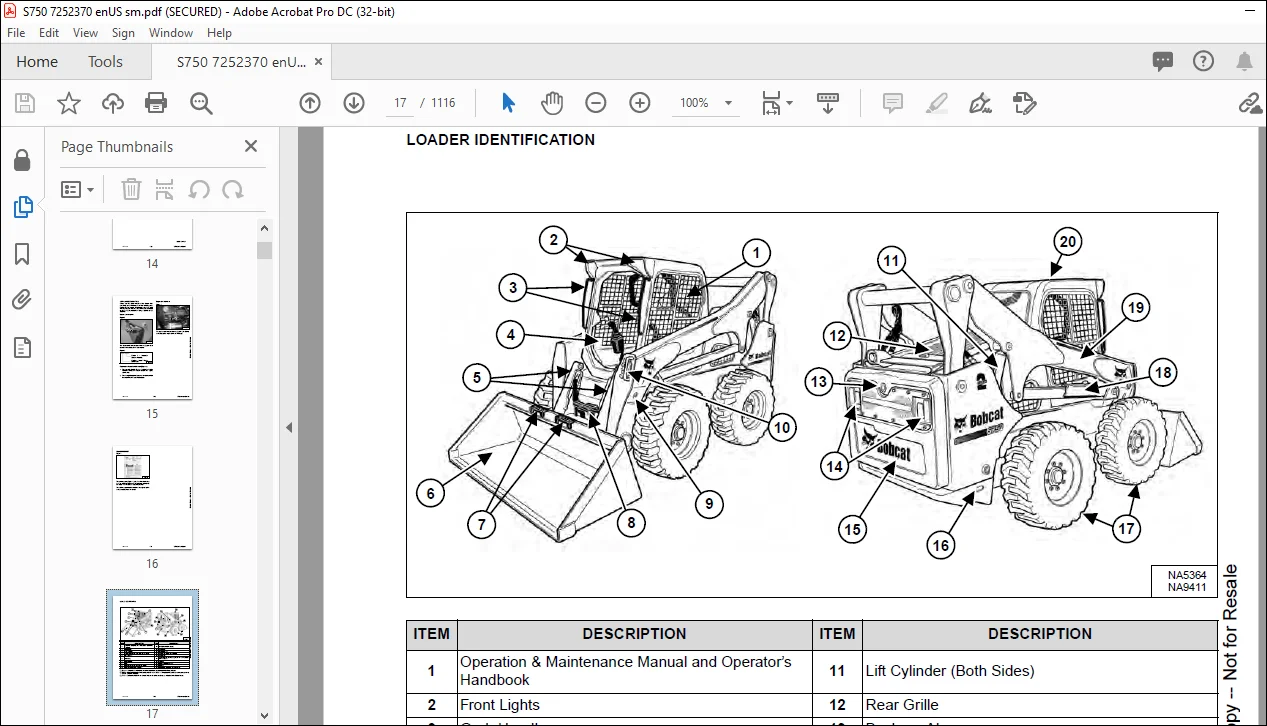
LOADER IDENTIFICATION 17
SAFETY AND MAINTENANCE 19
LIFTING AND BLOCKING THE LOADER 23
Procedure 23
LIFT ARM SUPPORT DEVICE 25
Description 25
Installing 26
Removing 27
OPERATOR CAB 29
Description 29
Raising 30
Lowering 31
Cab Door Sensor 32
Special Applications Kit 33
Special Applications Kit Inspection And Maintenance 33
Forestry Door And Window Kit 34
Forestry Door And Window Kit Inspection And Maintenance 34
TRANSPORTING THE LOADER ON A TRAILER 35
Loading And Unloading 35
Fastening 35
TOWING THE LOADER 37
Procedure 37
REMOTE START TOOL KIT – MEL1563 39
Remote Start Tool – MEL1563 39
Service Tool Harness Communicator – MEL1566 41
Remote Start Procedure 41
REMOTE START TOOL (SERVICE TOOL) KIT – 7217666 45
Description 45
Remote Start Tool (Service Tool) – 7022042 46
Loader Service Tool Harness – 6689747 47
Computer Service Tool Harness – 6689746 48
Remote Start Procedure 49
SERVICE SCHEDULE 53
Maintenance Intervals 53
ENGINE AIR CLEANER 55
Replacing Filters 55
ENGINE COOLING SYSTEM 57
Maintenance Platform 57
Cleaning 57
Checking And Adding Coolant 60
Removing And Replacing Coolant 61
FUEL SYSTEM 63
Fuel Specifications 63
Biodiesel Blend Fuel 63
Filling The Fuel Tank 64
Fuel Filter 65
Removing Air From The Fuel System 66
DIESEL EXHAUST FLUID (DEF) / ADBLUE® SYSTEM 67
Description 67
Filling The DEF / AdBlue® Tank 67
ENGINE LUBRICATION SYSTEM 69
Checking And Adding Engine Oil 69
Engine Oil Chart 69
Removing And Replacing Oil And Filter 70
HYDRAULIC / HYDROSTATIC SYSTEM 73
Checking And Adding Fluid 73
Hydraulic / Hydrostatic Fluid Chart 73
Removing And Replacing Hydraulic Fluid 74
Removing And Replacing Hydraulic / Hydrostatic Filter 76
Removing And Replacing Hydraulic Charge Filter 77
Replacing Reservoir Breather Cap 78
FINAL DRIVE TRANSMISSION (CHAINCASE) 79
Checking And Adding Fluid 79
Removing And Replacing Fluid 79
BOB-TACH (HAND LEVER) 81
Inspection And Maintenance 81
BOB-TACH (POWER) 83
Inspection And Maintenance 83
LUBRICATING THE LOADER 85
Lubrication Locations 85
TIRE MAINTENANCE 89
Wheel Nuts 89
Rotating 89
Mounting 90
PIVOT PINS 91
Inspection And Maintenance 91
LOADER STORAGE AND RETURN TO SERVICE 93
Storage 93
Return To Service 93
STOPPING THE ENGINE AND LEAVING THE LOADER 95
Procedure 95
EMERGENCY EXIT 97
Rear Window Identification 97
Rear Window Removal (Latches) 97
Rear Window Removal (Rubber Cord) 97
External Access (Rear Window With Latches) 98
External Access (Rear Window With Rubber Cord) 98
Front Door 98
SEAT BELT 101
Inspection And Maintenance 101
HYDRAULIC SYSTEM 103
HYDRAULIC / HYDROSTATIC SCHEMATICS 109
HYDRAULIC SYSTEM INFORMATION 117
Glossary Of Hydraulic / Hydrostatic Symbols 117
Troubleshooting 121
CYLINDER (LIFT) 123
Testing 123
Removal And Installation 124
Parts Identification 128
Disassembly 129
Assembly 131
CYLINDER (TILT) 135
Testing 135
Removal And Installation 136
Base End Pivot Pin Removal And Installation 138
Parts Identification 139
Disassembly 140
Assembly 142
CYLINDER (BOB-TACH) 145
Testing 145
Removal And Installation 146
Parts Identification 147
Disassembly 148
Assembly 149
MAIN RELIEF VALVE 153
Description 153
Testing 154
Main Relief Valve Adjustment 156
Main Relief Valve Removal And Installation 156
Auxiliary Relief Valve Adjustment 157
Auxiliary Relief Valve Removal And Installation 158
HYDRAULIC CONTROL VALVE (STANDARD) 159
Description 159
Removal And Installation 160
Mount Bracket Removal And Installation 164
Identification Chart 165
Lift Load Check Valve Removal And Installation 166
Load Check Valve Removal And Installation (Tilt And Auxiliary) 167
Anti-Cavitation Valve Removal And Installation (Lift, Rod End) 168
Port Relief / Anti-Cavitation Valve Removal And Installation (Lift, Base End) 168
Port Relief / Anti-Cavitation Valve Removal And Installation (Tilt, Base End) 169
Port Relief / Anti-Cavitation Valve Removal And Installation (Tilt, Rod End) 169
Port Relief Valve Removal And Installation 170
Plug Removal And Installation 172
Rubber Boot Removal And Installation 173
End Cap Block Removal And Installation 173
Lift Spool And Detent Removal 174
Lift Spool And Detent Disassembly 176
Lift Spool And Detent Assembly 178
Lift Spool And Detent Installation 180
Tilt Spool Removal And Installation 182
Tilt Spool Disassembly And Assembly 183
Auxiliary Spool Removal And Installation 184
Auxiliary Solenoid Removal And Installation 185
Solenoid Removal And Installation 186
Lock Valve Removal And Installation 187
Lift Arm Bypass Orifice Removal And Installation 189
Main Relief Valve Removal And Installation 189
Auxiliary Relief Valve Removal And Installation 190
Check Valve Removal And Installation 190
HYDRAULIC CONTROL VALVE (ACS) OR (SJC) 193
Description 193
Removal And Installation 193
Actuator Removal And Installation (In Loader) 198
Actuator Removal And Installation (Out Of Loader) 199
Identification Chart 202
Mount Bracket Removal And Installation 203
Lift Load Check Valve Removal And Installation 203
Load Check Valve Removal And Installation (Tilt And Auxiliary) 204
Anti-Cavitation Valve Removal And Installation (Lift, Rod End) 205
Port Relief / Anti-Cavitation Valve Removal And Installation (Lift, Base End) 205
Port Relief / Anti-Cavitation Valve Removal And Installation (Tilt, Base End) 206
Port Relief / Anti-Cavitation Valve Removal And Installation (Tilt, Rod End) 206
Port Relief Valve Removal And Installation 207
Plug Removal And Installation 209
End Cap Block Removal And Installation 210
Lift Spool Removal And Installation 210
Lift Spool Disassembly And Assembly 212
Tilt Spool Removal And Installation 213
Auxiliary Spool Removal And Installation 215
Auxiliary Solenoid Removal And Installation 216
Solenoid Removal And Installation 217
Lock Valve Removal And Installation 218
Lift Arm Bypass Orifice Removal And Installation 220
Main Relief Valve Removal And Installation 220
Auxiliary Relief Valve Removal And Installation 221
Check Valve Removal And Installation 221
LIFT ARM BYPASS CONTROL VALVE 223
Description 223
Testing 223
Removal And Installation 224
Bracket Removal And Installation 225
Disassembly And Assembly 225
HYDRAULIC PUMP 227
Description 227
Pump Test At Quick Couplers 227
Direct Pump Test (Standard Section) 228
Direct Pump Test (Charge Section) 230
Removal And Installation 232
Hydraulic Pump Startup 234
Parts Identification 235
Disassembly And Assembly 236
HYDRAULIC PUMP (HIGH FLOW) 237
Description 237
Pump Test At Quick Couplers 237
Direct Pump Test (Standard Section) 238
Direct Pump Test (Charge Section) 239
Direct Pump Test (High Flow Section) 241
High Flow Relief Valve Adjustment 243
High Flow Relief Valve Removal And Installation 244
Solenoid Removal And Installation 245
Removal And Installation 246
Hydraulic Pump Startup 248
Parts Identification 249
Disassembly And Assembly 250
HYDRAULIC / HYDROSTATIC FILTERS 251
Description 251
Housing Removal And Installation 251
HYDRAULIC FLUID RESERVOIR 253
Description 253
Removal And Installation 253
Hydraulic Fluid Screen 254
OIL COOLER 255
Description 255
Removal And Installation 255
BUCKET POSITION VALVE 257
Description 257
Solenoid Removal And Installation 257
Solenoid Testing 259
Removal And Installation 259
Disassembly And Assembly 262
REAR AUXILIARY DIVERTER VALVE 263
Description 263
Solenoid Testing 263
Removal And Installation 264
Disassembly And Assembly 265
BOB-TACH (POWER) BLOCK 271
Description 271
Testing Relief Valve 272
Removal And Installation 274
Disassembly And Assembly 276
FRONT AUXILIARY HYDRAULIC COUPLER BLOCK 281
Description 281
Removal And Installation 282
Disassembly And Assembly (FFI/FI) 282
Disassembly And Assembly (FFH/FH) 284
AUTOMATIC RIDE CONTROL 287
Description 287
Removal And Installation 288
Checking The Pressure In The Accumulator 291
Adding Nitrogen To The Accumulator 293
HYDROSTATIC SYSTEM 295
HYDROSTATIC SYSTEM INFORMATION 297
Troubleshooting 297
Description 298
HYDROSTATIC DRIVE MOTOR 299
Description 299
Removal And Installation 300
Parts Identification 302
Disassembly And Assembly 303
HYDROSTATIC DRIVE MOTOR (TWO-SPEED) 307
Description 307
Removal And Installation 307
Parts Identification 310
Disassembly 311
Assembly 317
HYDROSTATIC MOTOR CARRIER 323
Description 323
Removal And Installation 324
Parts Identification 325
Disassembly 326
Assembly 327
HYDROSTATIC MOTOR CARRIER (SJC) 329
Description 329
Removal And Installation 330
Parts Identification 332
Disassembly 333
Assembly 335
CHARGE PRESSURE 337
Description 337
Testing 337
Sender Removal And Installation 339
Adjusting 340
HYDROSTATIC PUMP 343
Description 343
Removal And Installation 344
Hydrostatic Pump Startup 345
Replenishing / High Pressure Relief Valve Removal And Installation 345
Parts Identification (Left Half) 346
Parts Identification (Right Half) 347
Disassembly 348
Assembly 355
HYDROSTATIC PUMP (SJC) 363
Description 363
Hydraulic Controller Removal And Installation 364
Removal And Installation 366
Hydrostatic Pump Startup 368
Parts Identification 369
High Pressure Relief And Bypass Valve 370
Charge Relief Valve 371
Disassembly 372
Inspection 381
Assembly 385
Mechanical NEUTRAL Adjustment 395
Hydraulic Controller NEUTRAL Adjustment 398
DRIVE BELT 401
Belt Adjustment 401
Stop Adjustment 401
Belt Replacement 402
Tensioner Pulley Removal And Installation (Earlier Models) 404
Tensioner Pulley Disassembly And Assembly 404
Tensioner Pulley Removal And Installation (Later Models) 405
Tensioner Pulley Disassembly And Assembly 405
TWO-SPEED / BRAKE VALVE 407
Description 407
Valve Block Removal And Installation 408
Valve Block Disassembly And Assembly 410
DRAIN MANIFOLD 413
Description 413
Drain Manifold Removal And Installation 414
DRIVE SYSTEM 415
BRAKE (SINGLE SPEED) 417
Description 417
Disc Removal And Installation 417
BRAKE (TWO-SPEED) 419
Description 419
DRIVE COMPONENTS 421
Description 421
Axle Seal Removal And Installation 422
Axle, Sprocket And Bearings Removal And Installation 424
Chain Removal And Installation 429
CHAINCASE 431
Description 431
Front Cover Removal And Installation 431
Center Cover Removal And Installation 432
Rear Cover Removal And Installation 433
MAINFRAME 435
SEAT BAR 439
Description 439
Removal And Installation 439
Disassembly And Assembly 440
Compression Spring Disassembly And Assembly 441
OPERATOR CAB 443
Gas Spring Removal And Installation 443
Gas Spring Bracket Disassembly And Assembly 444
Removal And Installation 444
OPERATOR SEAT 447
Removal And Installation 447
Seat Belt Removal And Installation (Retractable) 447
Seat Belt And Bracket Removal And Installation (Standard) 448
Seat Belt Bracket Removal And Installation 448
OPERATOR SEAT (SUSPENSION) 449
Removal And Installation 449
Slide Rail Removal And Installation 449
Seat Belt Removal And Installation 450
Lower Cushion Removal 450
Lower Cushion Installation 451
Back Cushion Removal And Installation 451
Shock Removal And Installation 452
3-Point Seat Belt Removal And Installation 452
BOB-TACH (HAND LEVER) 455
Description 455
Removal And Installation 455
Lever And Wedge Disassembly And Assembly 457
Pivot Pin Bushing And Seal Removal And Installation 460
BOB-TACH (POWER) 461
Description 461
Removal And Installation 461
Lever And Wedge Disassembly And Assembly 464
Pivot Pin Bushing And Seal Removal And Installation 466
LIFT ARMS 467
Stabilizer Bar Removal And Installation 467
Link Removal And Installation 468
Removal And Installation 469
REAR GRILLE 473
Removing 473
Installing 473
Shield Removal And Installation 474
ENGINE COVER 475
Removal And Installation 475
REAR DOOR (TAILGATE) 477
Removal And Installation 477
Striker Removal And Installation 478
Striker Disassembly And Assembly 478
Striker (Adjusting) 478
Latch Removal And Installation 479
Tailgate Fan Removal And Installation 480
FUEL TANK 481
Removal And Installation 481
Fuel Level Sender Removal And Installation 482
Fuel Fill Screen Removal And Installation 483
CONTROL PEDALS AND LINKAGES 485
Description 485
Pedal Removal And Installation 485
Linkage Removal And Installation 486
Pedal (Adjusting) 487
Floor Pan Removal And Installation 488
CONTROL PEDALS AND LINKAGES (ACS) 489
Description 489
Pedal Removal And Installation 489
Linkage Removal And Installation 490
Pedal (Adjusting) 490
Floor Pan Removal And Installation 491
CONTROL PANEL 493
Description 493
Removal And Installation 494
Disassembly And Assembly 495
Linkage Removal And Installation 499
Pintle Arm Disassembly And Assembly 503
Linkage NEUTRAL (Adjusting) 504
Linkage Travel (Adjusting) 508
Shock Removal And Installation 512
CONTROL PANEL (SJC) 513
Description 513
Removal And Installation 513
CONTROL HANDLE / LEVER 515
Description 515
Lever Removal And Installation 515
Boot Removal And Installation 516
CONTROL HANDLE / LEVER (ACS) 517
Description 517
Handle Sensor Removal And Installation 517
Handle Removal And Installation 520
Handle Disassembly And Assembly 521
Lever Removal And Installation 521
Boot Removal And Installation 522
CONTROL HANDLE / LEVER (SJC) 523
Description 523
Joystick Testing 523
Joystick Removal And Installation 524
ACCESS PANEL (INSIDE) 525
Removal And Installation (Left) 525
Removal And Installation (Right) 525
ACCESS PANEL (INSIDE) (SJC) 527
Removal And Installation (Left) 527
Removal And Installation (Right) 527
WINDOW (REAR) 529
Rear Window Identification 529
Rear Window Removal (Latches) 529
Rear Window Removal (Rubber Cord) 529
External Access (Rear Window With Latches) 530
External Access (Rear Window With Rubber Cord) 530
WINDOW (TOP) 531
Removal And Installation 531
WINDOW (SIDE) 533
Removal And Installation 533
CAB DOOR 535
Description 535
Removal And Installation 535
Disassembly And Assembly 536
Aligning 537
Adjusting 538
Checking Operation 538
ARMREST 539
Description 539
Removal And Installation 540
Disassembly And Assembly 541
LEFT SIDE LOWER PANEL 543
Removal And Installation 543
Disassembly And Assembly 546
RIGHT SIDE LOWER PANEL 547
Removal And Installation 547
Disassembly And Assembly 549
HEADLINER 551
Removal And Installation 551
FAN DUCT PANELS 553
Removal And Installation 553
ELECTRICAL SYSTEM 555
ELECTRICAL SCHEMATICS 561
ELECTRICAL SYSTEM INFORMATION 679
Glossary Of Electrical Symbols 679
Standard Cab Harness Connectors 682
Deluxe Cab Harness Connectors 683
Mainframe Manual Harness Connectors 684
Mainframe SJC, AHC, ACS Harness Connectors 685
Engine Harness Connectors 686
Description 687
Troubleshooting 688
Fuse And Relay Location / Identification 689
Solenoid Testing 694
BATTERY 695
Removal And Installation 695
Battery Maintenance 696
Maintaining Battery Charge Level 696
Battery Service During Machine Storage 696
Battery Testing 697
Battery Charging 697
Using A Booster Battery (Jump Starting) 698
ALTERNATOR 699
Belt Adjustment 699
Belt Replacement 699
Charging System Inspection 700
Alternator Voltage Testing 701
Low Voltage Testing 701
High Voltage Testing 702
Removal And Installation 703
Parts Identification 705
STARTER 707
Testing 707
Removal And Installation 707
Parts Identification 708
INSTRUMENT PANELS 709
Left Panel 709
Display Screen 711
Right Panel (Standard Key Panel) 712
Right Panel (Keyless Start Panel) 713
Right Panel (Deluxe Instrumentation Panel) 714
Left Switch Panel 716
Right Switch Panel 716
Left Side Lower Panel 717
Right Side Lower Panel 717
Left Panel Removal And Installation 718
Right Panel (Standard Key Panel) Removal And Installation 718
Right Panel (Keyless Start Panel) Removal And Installation 719
Right Panel (Deluxe Instrumentation Panel) Removal And Installation 719
Key Switch Disassembly And Assembly 720
Alarm Disassembly And Assembly 720
Left Switch Panel Removal And Installation 721
Right Switch Panel Removal And Installation 721
LIGHTS 723
Front Removal And Installation 723
Rear Removal And Installation 724
Cab Light Removal And Installation 724
BOBCAT CONTROLLERS (GATEWAY AND AUXILIARY) 725
Description 725
Connector Identification 726
Removal And Installation 732
BOBCAT CONTROLLER (ACS) 733
Description 733
Connector And Wire Identification 734
Removal And Installation 735
BOBCAT CONTROLLER (SJC) (DRIVE) 737
Description 737
Connector Identification 738
Removal And Installation 740
DOSING CONTROL UNIT (DCU) 741
Description 741
Removal And installation 741
ENGINE CONTROL UNIT (ECU) 743
Description 743
Cleaning 744
Removal And Installation 745
DIAGNOSTIC SERVICE CODES 747
Viewing Service Codes 747
Service Codes List 748
BOBCAT INTERLOCK CONTROL SYSTEM (BICS™) 763
Description 763
Operation 763
Inspecting The BICS™ (Engine STOPPED – Key ON) 764
Inspecting Deactivation Of The Auxiliary Hydraulics System (Engine STOPPED – Key ON) 764
Inspecting The Seat Bar Sensor (Engine RUNNING) 764
Inspecting The Traction Lock And Parking Brake (Engine RUNNING) 764
Inspecting The Lift Arm Bypass Control 764
Inspecting Deactivation Of Lift And Tilt Functions (ACS And SJC) 764
Troubleshooting 765
SEAT BAR SENSOR 767
Description 767
Troubleshooting 767
Testing 768
Removal 769
Installation 770
Bobcat Interlock Control System (BICS™) Circuit Test 772
TRACTION LOCK 775
Description 775
Troubleshooting 776
Inspecting 777
CONTROL SYSTEM (ACS) 779
Description 779
Troubleshooting 780
Handle Sensor Connector Disassembly And Assembly 781
Switch Handle Removal 782
Switch Handle Installation 784
Actuator Connector Disassembly And Assembly 787
Handle Lock Solenoid Removal And Installation 788
Handle Lock Solenoid Disassembly And Assembly 788
Foot Sensor Removal And Installation 789
Foot Sensor Disassembly And Assembly 790
Foot Sensor Lock Solenoid Removal And Installation 790
ELECTRICAL / HYDRAULIC CONTROLS 791
Identification Chart 791
Description 792
Identification Chart ACD Group 0 793
Identification Chart ACD Group 1 794
Identification Chart ACD Group 2 795
Identification Chart ACD Group 3 796
ELECTRICAL / HYDRAULIC CONTROLS (ACS) 797
Identification Chart 797
Description 798
Identification Chart ACD Group 0 799
Identification Chart ACD Group 1 800
Identification Chart ACD Group 2 801
Identification Chart ACD Group 3 802
ELECTRICAL / HYDRAULIC CONTROLS (SJC) 803
Identification Chart 803
Description 804
Identification Chart ACD Group 0 805
Identification Chart ACD Group 1 806
Identification Chart ACD Group 2 807
Identification Chart ACD Group 3 808
SERVICE PC (LAPTOP COMPUTER) 809
Connecting Remote Start Tool 809
Connecting Remote Start Tool (Service Tool) 809
CALIBRATION 811
Description 811
Actuator Testing 811
Lift And Tilt Calibration (SJC) 814
Hydrostatic Pump Calibration (SJC) 816
Lift And Tilt Calibration (ACS) 821
STEERING DRIFT COMPENSATION (OPERATOR MODE) 823
Description 823
Operation 823
STEERING DRIFT COMPENSATION (SERVICE MODE) 825
Description 825
Operation 825
CONTROL PANEL SETUP 827
Right Panel Setup (Deluxe Instrumentation Panel) 827
PASSWORD SETUP (DELUXE INSTRUMENTATION PANEL) 831
Password Description 831
Changing The Owner Password 831
Changing The User Passwords 832
Password Lockout Feature 832
PASSWORD SETUP (KEYLESS START PANEL) 833
Password Description 833
Changing The Owner Password 833
Password Lockout Feature 833
MAINTENANCE CLOCK 835
Description 835
Setup 836
Reset 839
BACK-UP ALARM SYSTEM 841
Description 841
Inspection 841
Adjusting Switch Position 842
Troubleshooting (Standard And ACS) 843
Troubleshooting (Joystick) 844
Alarm Removal And Installation 845
Switch Removal And Installation 845
FRONT HORN 847
Removal And Installation 847
Troubleshooting 848
Troubleshooting (Joystick) 849
CAMSHAFT AND CRANKSHAFT POSITION SENSOR 851
Removal And Installation 851
ENGINE COMPARTMENT TEMPERATURE SENSOR 853
Removal And Installation 853
ENGINE SERVICE 855
ENGINE INFORMATION 859
Description 859
Specifications 860
Sensor Location 862
Torque Values 869
Troubleshooting 871
Engine Removal And Installation 873
Engine Mount Replacement 884
Compression – Testing 886
Injector Signal – Testing 888
Injector Signal – Testing (In-Line) 890
Oil Pressure Testing (At Oil Sensor On Block) 892
Oil Pressure Testing (At Turbocharger Oil Inlet) 894
ENGINE SPEED CONTROL (HAND) 897
Removal And Installation 897
ENGINE SPEED CONTROL (FOOT) 899
Removal And Installation 899
Disassembly And Assembly 900
Foot Throttle Calibration 902
SELECTIVE CATALYTIC REDUCTION (SCR) SYSTEM 905
Description 905
Diesel Exhaust Fluid (DEF) / AdBlue® Level 906
DeSOX Process 907
SCR System Codes 909
Diesel Exhaust Fluid (DEF) / AdBlue® Unsatisfactory Quality 910
SCR System Component Tampering 910
EGR Impeded 911
Diesel Exhaust Fluid (DEF) / AdBlue® Dosing Interruption 911
SCR Removal And Installation 912
Dosing Module Removal And Installation 914
Dosing Control Unit (DCU) Removal And Installation 915
Supply Module Removal And Installation 917
Supply Module Filter Removal And Installation 918
Diesel Exhaust Fluid (DEF) / AdBlue® Tank Removal And Installation 920
Diesel Exhaust Fluid (DEF) / AdBlue® Sensor Removal And Installation 923
Diesel Exhaust Fluid (DEF) / AdBlue® Coolant Valve Removal And Installation 925
DIESEL OXIDATION CATALYST (DOC) 927
Removal And Installation 927
AIR CLEANER 929
Housing Removal And Installation 929
ENGINE COOLING SYSTEM 931
Radiator Removal And Installation 931
Hydraulic Fan Description 934
Reversible Hydraulic Fan Description 934
Fan Duct Removal And Installation 934
Hydraulic Fan Motor Assembly Removal And Installation 935
Hydraulic Fan Motor Removal And Installation 936
Hydraulic Fan Motor Disassembly And Assembly 938
Blower Housing Removal And Installation 947
Water Pump Removal And Installation 948
Thermostat Housing Removal And Installation 949
Thermostat – Testing 949
LUBRICATION SYSTEM 951
Description 951
Oil Pan Removal And Installation 952
Oil Pump Removal And Installation 953
Oil Pump Relief Valve Description 954
Oil Suction Pipe Removal And Installation 954
Oil Cooler Removal And Installation 955
Oil Filter Head Removal And Installation 955
Oil Cooler Bypass Description 956
FUEL SYSTEM 957
Description 957
High Pressure Pump Removal And Installation 958
High Pressure Pump Drive Gear Removal And Installation 959
Fuel Cooler Removal And Installation 960
Fuel Cooler Bypass Valve Removal And Installation 960
Fuel Temperature Sensor Removal And Installation 960
Fuel Recirculation Valve Removal And Installation 961
Fuel Rail Assembly Removal And Installation 962
Fuel Injector Removal And Installation 963
Injector Coding 965
Removing Air From The Fuel System 967
CYLINDER HEAD 969
Intake Air Heater Removal And Installation 969
Intake Air Heater Tube Removal And Installation 970
Valve Clearance Adjustment 971
Cylinder Head Removal And Installation 973
Cylinder Head Disassembly And Assembly 976
Cylinder Head Inspection 977
Cylinder Head Top Clearance 978
Valve Step Height 979
Valve Stem Height 979
Valve Guide 980
Valve 980
Valve Spring 981
Rocker Arm Shaft Disassembly And Assembly 982
Rocker Arm Shaft Inspection 983
Push Rod Inspection 983
CRANKSHAFT AND PISTONS 985
Piston And Connecting Rod Removal And Installation 985
Piston And Connecting Rod Inspection 986
Timing Wheel Removal And Installation 988
Crankshaft Removal And Installation 990
Cylinder Block Inspection 992
Crankshaft Inspection 994
Connecting Rod Inspection 994
Engine Component Class 995
CAMSHAFT 997
Removal And Installation 997
Inspecting 998
GEARCASE 1001
Gear Backlash 1001
Gear End Play 1001
Gear Timing 1002
Idle Gear Removal And Installation 1003
Idle Gear Inspection 1003
TURBOCHARGER 1005
Description 1005
Removal And Installation 1005
Testing 1007
FLYWHEEL AND HOUSING 1009
Flywheel Removal And Installation 1009
Ring Gear Removal And Installation 1009
Housing Removal And Installation 1010
EXHAUST GAS RECIRCULATION (EGR) SYSTEM 1011
Description 1011
Removal And Installation 1012
HEATING, VENTILATION AND AIR CONDITIONING (HVAC) 1015
AIR CONDITIONING SYSTEM FLOW 1017
Description 1017
Chart 1018
Components 1019
Safety Equipment 1022
REGULAR MAINTENANCE 1023
Filters 1023
Belt Adjustment 1024
Belt Replacement 1024
Condenser 1025
Air Conditioning Lubrication 1025
Air Conditioning Service Chart 1026
Air Conditioning Evaporator / Heater Coil 1027
TROUBLESHOOTING 1029
Blower Motor Does Not Operate 1029
Blower Motor Operates Normally, But Air Flow Is Insufficient 1029
Insufficient Cooling Although Air Flow And Compressor Operation Are Normal 1029
The Compressor Does Not Operate At All, Or Operates Improperly 1029
Gauge Pressure Related Troubleshooting 1030
Troubleshooting Tree 1032
Temperature / Pressure Chart 1035
Poor A/C Performance 1037
HVAC Repair And Leaks 1038
Electrical System 1039
Engine Coolant Bypassing The Heater Valve 1045
Heater Valve Not Opening Or Closing 1046
SYSTEM CHARGING AND RECLAMATION 1047
Refrigerant Identification 1047
Reclamation And Charging With Recovery / Charging Unit 1048
COMPRESSOR 1051
Removal And Installation 1051
Oil 1053
Oil Check 1054
CONDENSER 1055
Removal And Installation 1055
RECEIVER / DRIER 1057
Receiver / Drier Removal And Installation 1057
Pressure Switch Removal And Installation 1059
Schrader® Valve Removal And Installation 1060
EVAPORATOR / HEATER UNIT 1061
Removal And Installation 1061
THERMOSTAT 1063
Description 1063
Removal And Installation 1064
EXPANSION VALVE 1065
Removal And Installation 1065
EVAPORATOR COIL 1067
Removal And Installation 1067
HEATER COIL 1069
Removal And Installation 1069
BLOWER FAN 1071
Removal And Installation 1071
Disassembly And Assembly 1071
HEATER VALVE 1075
Removal And Installation 1075
EVAPORATOR / HEATER COVER 1077
Removing 1077
Installing 1077
SPECIFICATIONS 1079
LOADER SPECIFICATIONS 1081
Machine Dimensions 1081
Performance 1082
Engine 1082
Drive System 1083
Controls 1083
Hydraulic System 1084
Electrical System 1085
Capacities 1085
Tires 1086
TECHINCAL SERVICE GUIDE SPECIFICATIONS 1087
Engine 1087
Engine Torques 1087
Cooling System 1087
Loader Torques 1088
Hydraulic / Hydrostatic System 1088
Fuel Consumption 1088
TORQUE SPECIFICATIONS FOR BOLTS 1089
Torque For General SAE Bolts 1089
Torque For General Metric Bolts 1090
HYDRAULIC CONNECTION SPECIFICATIONS 1091
Straight Thread O-ring Fitting 1091
Flare Fitting 1092
Tubelines And Hoses 1092
HYDRAULIC / HYDROSTATIC FLUID SPECIFICATIONS 1093
Specifications 1093
CONVERSIONS 1095
Decimal And Millimeter Equivalent Chart 1095
U S To Metric Conversion Chart 1095
SERVICE TOOLS REQUIRED 1097
Remote Start Tools 1097
Hydraulic Tools 1098
Mainframe And Drive Tools 1101
Electrical Tools 1104
Engine Tools 1105
HVAC Tools 1110
ALPHABETICAL INDEX 1111
IMAGES PREVIEW OF THE MANUAL:
Questions? Email us: [email protected]
PLEASE NOTE:
- This is the SAME MANUAL used by the dealerships to diagnose your vehicle
- No waiting for couriers / posts as this is a PDF manual and you can download it within 2 minutes time once you make the payment.
- Your payment is all safe and the delivery of the manual is INSTANT – You will be taken to the DOWNLOAD PAGE.
- So have no hesitations whatsoever and write to us about any queries you may have : heydownloadss @gmail.com
S.V