Bobcat S750 Skid-Steer Loader Service Manual SN ATDZ11001 & Above – PDF DOWNLOAD
$36.95
Bobcat S750 Skid-Steer Loader Service Manual SN ATDZ11001 & Above – PDF DOWNLOAD
Description
Bobcat S750 Skid-Steer Loader Service Manual SN ATDZ11001 & Above – PDF DOWNLOAD
FILE DETAILS:
Bobcat S750 Skid-Steer Loader Service Manual SN ATDZ11001 & Above – PDF DOWNLOAD
Language : English
Pages : 1262
Downloadable : Yes
File Type : PDF
DESCRIPTION:
Bobcat S750 Skid-Steer Loader Service Manual SN ATDZ11001 & Above – PDF DOWNLOAD
FOREWORD:
This manual is for the Bobcat loader mechanic. It provides necessary servicing and adjustment procedures for the Bobcat loader and its component parts and systems. Refer to the Operation & Maintenance Manual for operating instructions, starting procedure, daily checks, etc.
A general inspection of the following items must be made after the loader has had service or repair:
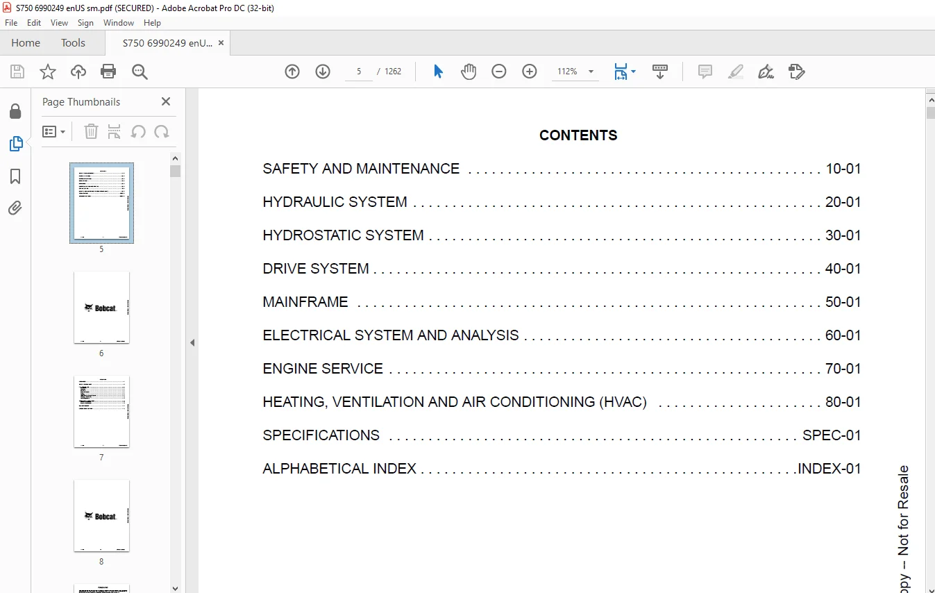
TABLE OF CONTENTS:
Bobcat S750 Skid-Steer Loader Service Manual SN ATDZ11001 & Above – PDF DOWNLOAD
MAINTENANCE SAFETY 3
CONTENTS 5
FOREWORD 7
FOREWORD 9
SAFETY INSTRUCTIONS 11
FIRE PREVENTION 13
Maintenance 13
Operation 13
Electrical 13
Hydraulic System 13
Fueling 13
Starting 13
Spark Arrester Exhaust System 13
Welding And Grinding 14
Fire Extinguishers 14
SERIAL NUMBER LOCATIONS 15
Loader Serial Number 15
Engine Serial Number 15
DELIVERY REPORT 16
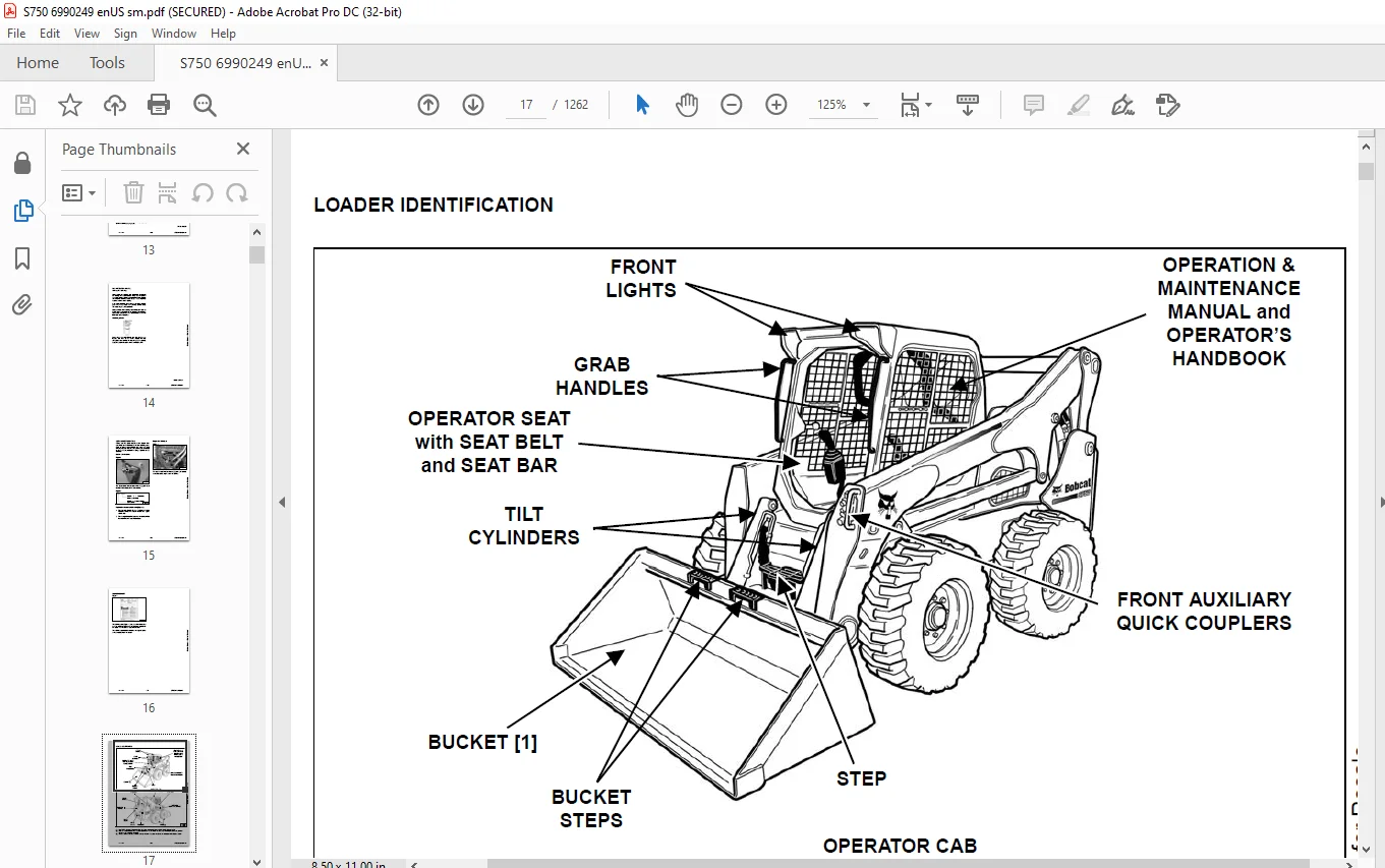
LOADER IDENTIFICATION 17
SAFETY AND MAINTENANCE 19
LIFTING AND BLOCKING THE LOADER 23
Procedure 23
LIFT ARM SUPPORT DEVICE 25
Description 25
Installing 25
Removing 26
OPERATOR CAB 27
Description 27
Raising 28
Lowering 29
Cab Door Sensor 30
Special Applications Kit 31
Special Applications Kit Inspection And Maintenance 31
Forestry Door And Window Kit 32
Forestry Door And Window Kit Inspection And Maintenance 32
TRANSPORTING THE LOADER ON A TRAILER 33
Loading And Unloading 33
Fastening 33
TOWING THE LOADER 35
Procedure 35
REMOTE START TOOL KIT – MEL1563 37
Remote Start Tool – MEL1563 37
Service Tool Harness Communicator – MEL1566 39
Remote Start Procedure 39
REMOTE START TOOL (SERVICE TOOL) KIT – 7217666 43
Description 43
Remote Start Tool (Service Tool) – 7022042 44
Loader Service Tool Harness – 6689747 45
Computer Service Tool Harness – 6689746 46
Remote Start Procedure 47
DIAGMASTER (SERVICE TOOL) KIT – 7024161 51
Diagmaster (Service Tool) 51
DST-i LED Table 52
DST-i Operation Status And Display Specification 52
Diagmaster (Service Tool) Procedure 53
SERVICE SCHEDULE 57
Maintenance Intervals 57
ENGINE AIR CLEANER 59
Replacing Filter Elements 59
ENGINE COOLING SYSTEM 61
Maintenance Platform 61
Cleaning 61
Checking And Adding Coolant 63
Removing And Replacing Coolant 64
FUEL SYSTEM 65
Fuel Specifications 65
Biodiesel Blend Fuel 65
Filling The Fuel Tank 66
Fuel Filter 67
Removing Air From The Fuel System 68
ENGINE LUBRICATION SYSTEM 69
Checking And Adding Engine Oil 69
Engine Oil Chart 69
Removing And Replacing Oil And Filter 70
Removing And Replacing Crankcase Ventilation Filter 72
HYDRAULIC / HYDROSTATIC SYSTEM 73
Checking And Adding Fluid 73
Hydraulic / Hydrostatic Fluid Chart 73
Removing And Replacing Hydraulic Fluid 74
Removing And Replacing Hydraulic / Hydrostatic Filter 76
Removing And Replacing Hydraulic Charge Filter 77
Replacing Reservoir Breather Cap 78
FINAL DRIVE TRANSMISSION (CHAINCASE) 79
Checking And Adding Fluid 79
Removing And Replacing Fluid 79
BOB-TACH (HAND LEVER) 81
Inspection And Maintenance 81
BOB-TACH (POWER) 83
Inspection And Maintenance 83
LUBRICATING THE LOADER 85
Lubrication Locations 85
TIRE MAINTENANCE 89
Wheel Nuts 89
Rotating 89
Mounting 90
DIESEL PARTICULATE FILTER (DPF) SYSTEM 91
Description 91
Remote Parked Regeneration 91
Service Regeneration 93
DPF Cleaning 94
PIVOT PINS 95
Inspection And Maintenance 95
LOADER STORAGE AND RETURN TO SERVICE 97
Storage 97
Return To Service 97
STOPPING THE ENGINE AND LEAVING THE LOADER 99
Procedure 99
EMERGENCY EXIT 101
Rear Window Identification 101
Rear Window Removal (Latches) 101
Rear Window Removal (Rubber Cord) 101
External Access (Rear Window With Latches) 102
External Access (Rear Window With Rubber Cord) 102
Front Door 102
SEAT BELT 105
Inspection And Maintenance 105
HYDRAULIC SYSTEM 107
HYDRAULIC / HYDROSTATIC SCHEMATICS 113
HYDRAULIC SYSTEM INFORMATION 125
Glossary Of Hydraulic / Hydrostatic Symbols 125
Troubleshooting 129
CYLINDER (LIFT) 131
Testing 131
Removal And Installation 132
Parts Identification 136
Disassembly 137
Assembly 138
CYLINDER (TILT) 143
Testing 143
Removal And Installation 144
Base End Pivot Pin Removal And Installation 146
Parts Identification 147
Parts Identification (Later Models) 148
Disassembly 149
Assembly 152
CYLINDER (BOB-TACH) 157
Testing 157
Removal And Installation 158
Parts Identification 159
Disassembly 160
Assembly 161
MAIN RELIEF VALVE (EARLY MODELS) 165
Description 165
Testing 166
Adjusting 168
Removal And Installation 168
MAIN RELIEF VALVE (LATER MODELS) 171
Description 171
Testing 172
Main Relief Valve Adjustment 174
Main Relief Valve Removal And Installation 174
Auxiliary Relief Valve Adjustment 175
Auxiliary Relief Valve Removal And Installation 176
HYDRAULIC CONTROL VALVE (STANDARD) (EARLY MODELS) 177
Description 177
Removal And Installation 178
Mount Bracket Removal And Installation 182
Identification Chart 183
Lift Load Check Valve Removal And Installation 184
Load Check Valve Removal And Installation (Tilt And Auxiliary) 185
Anti-Cavitation Valve Removal And Installation (Lift, Rod End) 186
Port Relief / Anti-Cavitation Valve Removal And Installation (Lift, Base End) 186
Port Relief / Anti-Cavitation Valve Removal And Installation (Tilt, Base End) 187
Port Relief / Anti-Cavitation Valve Removal And Installation (Tilt, Rod End) 187
Port Relief Valve Removal And Installation 188
Plug Removal And Installation 189
Rubber Boot Removal And Installation 190
End Cap Block Removal And Installation 191
Lift Spool And Detent Removal And Installation 192
Tilt Spool Removal And Installation 202
Auxiliary Spool Removal And Installation 204
Auxiliary Solenoid Removal And Installation 206
Solenoid Removal And Installation 207
Lock Valve Removal And Installation 208
Lift Arm Bypass Orifice Removal And Installation 210
Main Relief Valve Removal And Installation 210
Check Valve Removal And Installation 211
HYDRAULIC CONTROL VALVE (STANDARD) (LATER MODELS) 213
Description 213
Removal And Installation 214
Mount Bracket Removal And Installation 218
Identification Chart 219
Lift Load Check Valve Removal And Installation 220
Load Check Valve Removal And Installation (Tilt And Auxiliary) 221
Anti-Cavitation Valve Removal And Installation (Lift, Rod End) 222
Port Relief / Anti-Cavitation Valve Removal And Installation (Lift, Base End) 222
Port Relief / Anti-Cavitation Valve Removal And Installation (Tilt, Base End) 223
Port Relief / Anti-Cavitation Valve Removal And Installation (Tilt, Rod End) 223
Port Relief Valve Removal And Installation 224
Plug Removal And Installation 226
Rubber Boot Removal And Installation 227
End Cap Block Removal And Installation 227
Lift Spool And Detent Removal And Installation 228
Tilt Spool Removal And Installation 236
Auxiliary Spool Removal And Installation 238
Auxiliary Solenoid Removal And Installation 239
Solenoid Removal And Installation 240
Lock Valve Removal And Installation 241
Lift Arm Bypass Orifice Removal And Installation 243
Main Relief Valve Removal And Installation 243
Auxiliary Relief Valve Removal And Installation 244
Check Valve Removal And Installation 244
HYDRAULIC CONTROL VALVE (ACS) OR (SJC) (EARLY MODELS) 247
Description 247
Removal And Installation 247
Actuator Removal And Installation (In Loader) 252
Actuator Removal And Installation (Out Of Loader) 254
Identification Chart 257
Mount Bracket Removal And Installation 258
Lift Load Check Valve Removal And Installation 258
Load Check Valve Removal And Installation (Tilt And Auxiliary) 259
Anti-Cavitation Valve Removal And Installation (Lift, Rod End) 260
Port Relief / Anti-Cavitation Valve Removal And Installation (Lift, Base End) 260
Port Relief / Anti-Cavitation Valve Removal And Installation (Tilt, Base End) 261
Port Relief / Anti-Cavitation Valve Removal And Installation (Tilt, Rod End) 261
Port Relief Valve Removal And Installation 262
Plug Removal And Installation 263
End Cap Block Removal And Installation 264
Lift Spool Removal And Installation 264
Lift Spool Disassembly And Assembly 266
Tilt Spool Removal And Installation 268
Auxiliary Spool Removal And Installation 270
Auxiliary Solenoid Removal And Installation 271
Solenoid Removal And Installation 272
Lock Valve Removal And Installation 273
Lift Arm Bypass Orifice Removal And Installation 274
Main Relief Valve Removal And Installation 274
Check Valve Removal And Installation 275
HYDRAULIC CONTROL VALVE (ACS) OR (SJC) (LATER MODELS) 277
Description 277
Removal And Installation 277
Actuator Removal And Installation (In Loader) 282
Actuator Removal And Installation (Out Of Loader) 283
Identification Chart 286
Mount Bracket Removal And Installation 287
Lift Load Check Valve Removal And Installation 287
Load Check Valve Removal And Installation (Tilt And Auxiliary) 288
Anti-Cavitation Valve Removal And Installation (Lift, Rod End) 289
Port Relief / Anti-Cavitation Valve Removal And Installation (Lift, Base End) 289
Port Relief / Anti-Cavitation Valve Removal And Installation (Tilt, Base End) 290
Port Relief / Anti-Cavitation Valve Removal And Installation (Tilt, Rod End) 290
Port Relief Valve Removal And Installation 291
Plug Removal And Installation 293
End Cap Block Removal And Installation 294
Lift Spool Removal And Installation 294
Lift Spool Disassembly And Assembly 296
Tilt Spool Removal And Installation 297
Auxiliary Spool Removal And Installation 299
Auxiliary Solenoid Removal And Installation 300
Solenoid Removal And Installation 301
Lock Valve Removal And Installation 302
Lift Arm Bypass Orifice Removal And Installation 304
Main Relief Valve Removal And Installation 304
Auxiliary Relief Valve Removal And Installation 305
Check Valve Removal And Installation 305
LIFT ARM BYPASS CONTROL VALVE 307
Description 307
Testing 307
Removal And Installation 308
Bracket Removal And Installation 309
Disassembly And Assembly 309
HYDRAULIC PUMP 311
Description 311
Pump Test At Quick Couplers 311
Direct Pump Test (Standard Section) 312
Direct Pump Test (Charge Section) 314
Removal And Installation 316
Hydraulic Pump Startup 318
Parts Identification 319
Disassembly And Assembly 320
HYDRAULIC PUMP (HIGH FLOW) 321
Description 321
Pump Test At Quick Couplers 321
Direct Pump Test (Standard Section) 322
Direct Pump Test (Charge Section) 323
Direct Pump Test (High Flow Section) 325
High Flow Relief Valve Adjustment 327
High Flow Relief Valve Removal And Installation 328
Solenoid Removal And Installation 329
Removal And Installation 330
Hydraulic Pump Startup 332
Parts Identification 333
Disassembly And Assembly 334
HYDRAULIC / HYDROSTATIC FILTERS 335
Description 335
Housing Removal And Installation 335
HYDRAULIC FLUID RESERVOIR 337
Description 337
Removal And Installation 337
Hydraulic Fluid Screen 338
OIL COOLER 339
Description 339
Removal And Installation 340
BUCKET POSITION VALVE 341
Description 341
Solenoid Removal And Installation 341
Solenoid Testing 343
Removal And Installation 343
Disassembly And Assembly 346
REAR AUXILIARY DIVERTER VALVE 347
Description 347
Solenoid Testing 347
Removal And Installation 348
Disassembly And Assembly 349
BOB-TACH (POWER) BLOCK 355
Description 355
Removal And Installation 355
Disassembly And Assembly 357
FRONT AUXILIARY HYDRAULIC COUPLER BLOCK 367
Description 367
Removal And Installation 368
Disassembly And Assembly (FFI/FI) 368
Disassembly And Assembly (FFH/FH) 370
HYDROSTATIC SYSTEM 373
HYDROSTATIC SYSTEM INFORMATION 375
Troubleshooting 375
Description 376
HYDROSTATIC DRIVE MOTOR 377
Description 377
Removal And Installation 378
Parts Identification 380
Disassembly And Assembly 381
HYDROSTATIC DRIVE MOTOR (TWO-SPEED) (S/N ATDZ11001 – ATDZ11599) 385
Description 385
Removal And Installation 385
Parts Identification 388
Disassembly 389
Assembly 395
HYDROSTATIC DRIVE MOTOR (TWO-SPEED) (S/N ATDZ11600 & ABOVE) 401
Description 401
Removal And Installation 401
Parts Identification 404
Disassembly 405
Assembly 411
HYDROSTATIC MOTOR CARRIER 417
Description 417
Removal And Installation 418
Parts Identification 419
Disassembly 420
Assembly 421
HYDROSTATIC MOTOR CARRIER (SJC) 423
Description 423
Removal And Installation 424
Parts Identification 426
Disassembly 427
Assembly 429
CHARGE PRESSURE 431
Description 431
Testing 431
Sender Removal And Installation 433
Adjusting 434
HYDROSTATIC PUMP 437
Description 437
Removal And Installation 438
Hydrostatic Pump Startup 439
Replenishing / High Pressure Relief Valve Removal And Installation 439
Parts Identification (Left Half) 440
Parts Identification (Right Half) 441
Disassembly 442
Assembly 449
HYDROSTATIC PUMP (SJC) 455
Description 455
Hydraulic Controller Removal And Installation 456
Removal And Installation 458
Hydrostatic Pump Startup 459
Parts Identification 460
High Pressure Relief And Bypass Valve 461
Charge Relief Valve 462
Disassembly 463
Inspection 472
Assembly 476
Mechanical Neutral Adjustment 484
Hydraulic Controller Neutral Adjustment 487
DRIVE BELT 491
Belt Adjustment 491
Stop Adjustment 491
Belt Replacement 491
Tensioner Pulley Removal And Installation 493
Tensioner Pulley Disassembly And Assembly 493
TWO-SPEED / BRAKE VALVE (S/N ATDZ11001 – ATDZ11599) 495
Description 495
Valve Block Removal And Installation 496
Valve Block Disassembly And Assembly 498
TWO-SPEED / BRAKE VALVE (S/N ATDZ11600 & ABOVE) 501
Description 501
Valve Block Removal And Installation 502
Valve Block Disassembly And Assembly 504
DRAIN MANIFOLD 507
Description 507
Drain Manifold Removal And Installation 508
DRIVE SYSTEM 509
BRAKE (SINGLE SPEED) 511
Description 511
Disc Removal And Installation 511
BRAKE (TWO-SPEED) 513
Description 513
DRIVE COMPONENTS 515
Description 515
Axle Seal Removal And Installation 516
Axle, Sprocket And Bearings Removal And Installation 518
Chain Removal And Installation 523
CHAINCASE 525
Description 525
Front Cover Removal And Installation 525
Center Cover Removal And Installation 526
Rear Cover Removal And Installation 527
MAINFRAME 529
SEAT BAR 533
Description 533
Removal And Installation 533
Disassembly And Assembly 534
Compression Spring Disassembly And Assembly 535
OPERATOR CAB 537
Gas Spring Removal And Installation 537
Gas Spring Bracket Disassembly And Assembly 538
Removal And Installation 538
OPERATOR SEAT 541
Removal And Installation 541
Seat Belt Removal And Installation (Retractable) 541
Seat Belt And Bracket Removal And Installation (Standard) 542
Seat Belt Bracket Removal And Installation 542
OPERATOR SEAT (SUSPENSION) 543
Removal And Installation 543
Slide Rail Removal And Installation 543
Seat Belt Removal And Installation 544
Lower Cushion Removal 544
Lower Cushion Installation 545
Back Cushion Removal And Installation 545
Shock Removal And Installation 546
3-Point Seat Belt Removal And Installation 546
BOB-TACH (HAND LEVER) 549
Description 549
Removal And Installation 549
Lever And Wedge Disassembly And Assembly 551
Pivot Pin Bushing And Seal Removal And Installation 553
BOB-TACH (POWER) 555
Description 555
Removal And Installation 555
Lever And Wedge Disassembly And Assembly 558
Pivot Pin Bushing And Seal Removal And Installation 559
LIFT ARMS 561
Stabilizer Bar Removal And Installation 561
Link Removal And Installation 562
Removal And Installation 563
REAR GRILLE 567
Removing 567
Installing 567
REAR DOOR (TAILGATE) 569
Removal And Installation 569
Striker Removal And Installation 570
Striker Disassembly And Assembly 570
Striker (Adjusting) 570
Latch Removal And Installation (Early Models) 571
Latch Removal And Installation (Later Models) 572
FUEL TANK 573
Removal And Installation 573
Fuel Level Sender Removal And Installation 575
Fuel Fill Screen Removal And Installation 575
CONTROL PEDALS AND LINKAGES 577
Description 577
Pedal Removal And Installation 577
Linkage Removal And Installation 578
Pedal (Adjusting) 579
Floor Pan Removal And Installation 580
CONTROL PEDALS AND LINKAGES (ACS) 581
Description 581
Pedal Removal And Installation 581
Linkage Removal And Installation 582
Pedal (Adjusting) 582
Floor Pan Removal And Installation 583
CONTROL PANEL 585
Description 585
Removal And Installation 586
Disassembly And Assembly 587
Linkage Removal And Installation 589
Pintle Arm Disassembly And Assembly 593
Linkage Neutral (Adjusting) 594
Linkage Travel (Adjusting) 598
Shock Removal And Installation 602
CONTROL PANEL (SJC) 603
Description 603
Removal And Installation 603
CONTROL HANDLE / LEVER 605
Description 605
Lever Removal And Installation 605
Boot Removal And Installation 606
CONTROL HANDLE / LEVER (ACS) 607
Description 607
Handle Sensor Removal And Installation 607
Handle Removal And Installation 610
Handle Disassembly And Assembly 611
Lever Removal And Installation 611
Boot Removal And Installation 612
CONTROL HANDLE / LEVER (SJC) 613
Description 613
Joystick Testing 613
Joystick Removal And Installation 614
ACCESS PANEL (INSIDE) 615
Removal And Installation (Left) 615
Removal And Installation (Right) 615
ACCESS PANEL (INSIDE) (SJC) 617
Removal And Installation (Left) 617
Removal And Installation (Right) 617
WINDOW (REAR) 619
Removal And Installation 619
Disassembly And Assembly 619
WINDOW (TOP) 621
Removal And Installation 621
WINDOW (SIDE) 623
Removal And Installation 623
CAB DOOR 625
Description 625
Removal And Installation 625
Disassembly And Assembly 626
Aligning 627
Adjusting 628
Checking Operation 628
ARMREST 629
Description 629
Removal And Installation 630
Disassembly And Assembly 631
LEFT SIDE LOWER PANEL 633
Removal And Installation 633
Disassembly And Assembly 635
RIGHT SIDE LOWER PANEL 637
Removal And Installation 637
Disassembly And Assembly 638
HEADLINER 641
Removal And Installation 641
ELECTRICAL SYSTEM AND ANALYSIS 643
ELECTRICAL SCHEMATICS 649
ELECTRICAL SYSTEM INFORMATION 845
Glossary Of Electrical Symbols 845
Standard Cab Harness Connectors 848
Deluxe Cab Harness Connectors 849
Mainframe Harness Connectors 850
Engine Harness Connectors 851
Description 852
Troubleshooting 853
Fuse And Relay Location / Identification 854
Solenoid Testing 856
BATTERY 857
Removal And Installation 857
Servicing 858
Using A Booster Battery (Jump Starting) 859
ALTERNATOR 861
Belt Adjustment 861
Belt Replacement 861
Charging System Inspection 862
Alternator Voltage Testing 863
Low Voltage Testing 863
High Voltage Testing 864
Removal And Installation 865
Parts Identification 867
STARTER 869
Testing 869
Removal And Installation 869
Parts Identification 870
INSTRUMENT PANELS 871
Left Panel 871
Display Screen 873
Right Panel (Standard Key Panel) 874
Right Panel (Keyless Start Panel) 875
Right Panel (Deluxe Instrumentation Panel) 876
Left Switch Panel 878
Right Switch Panel 878
Left Side Lower Panel 879
Right Side Lower Panel 879
Left Panel Removal And Installation 880
Right Panel (Standard Key Panel) Removal And Installation 880
Right Panel (Keyless Start Panel) Removal And Installation 881
Right Panel (Deluxe Instrumentation Panel) Removal And Installation 881
Key Switch Disassembly And Assembly 882
Alarm Disassembly And Assembly 882
Left Switch Panel Removal And Installation 883
Right Switch Panel Removal And Installation 883
LIGHTS 885
Front Removal And Installation 885
Rear Removal And Installation 886
Cab Light Removal And Installation 886
Cab Light Removal And Installation (Later Models) 887
BOBCAT CONTROLLERS (GATEWAY AND AUXILIARY) 889
Description 889
Connector Identification 890
Removal And Installation 896
BOBCAT CONTROLLER (ACS) 897
Description 897
Connector And Wire Identification 898
Removal And Installation 899
BOBCAT CONTROLLER (SJC) (DRIVE) 901
Description 901
Connector Identification 902
Removal And Installation 904
ENGINE CONTROL UNIT (ECU) 905
Description 905
Cleaning 906
Removal And Installation 907
DIAGNOSTIC SERVICE CODES 909
Viewing Service Codes 909
Service Codes List 910
DIAGMASTER DIAGNOSTIC TROUBLE CODES (DCT) 917
Viewing Trouble Codes 917
BOBCAT INTERLOCK CONTROL SYSTEM (BICS™) 919
Description 919
Operation 919
Inspecting The BICS™ (Engine STOPPED – Key ON) 920
Inspecting Deactivation Of The Auxiliary Hydraulics System (Engine STOPPED – Key ON) 920
Inspecting The Seat Bar Sensor (Engine RUNNING) 920
Inspecting The Traction Lock (Engine RUNNING) 920
Inspecting The Lift Arm Bypass Control 920
Inspecting Deactivation Of Lift And Tilt Functions (ACS And SJC) 920
Troubleshooting 921
SEAT BAR SENSOR 923
Description 923
Troubleshooting 923
Testing 924
Removal 925
Installation 926
Bobcat Interlock Control System (BICS™) Circuit Test 928
TRACTION LOCK 931
Description 931
Troubleshooting 932
Inspecting 933
CONTROL SYSTEM (ACS) 935
Description 935
Troubleshooting 936
Handle Sensor Connector Disassembly And Assembly 937
Switch Handle Removal 938
Switch Handle Installation 940
Actuator Connector Disassembly And Assembly 943
Handle Lock Solenoid Removal And Installation 944
Handle Lock Solenoid Disassembly And Assembly 944
Foot Sensor Removal And Installation 945
Foot Sensor Disassembly And Assembly 946
Foot Sensor Lock Solenoid Removal And Installation 946
ELECTRICAL / HYDRAULIC CONTROLS 947
Identification Chart 947
Description 948
Identification Chart ACD Group 0 949
Identification Chart ACD Group 1 950
Identification Chart ACD Group 2 951
Identification Chart ACD Group 3 952
ELECTRICAL / HYDRAULIC CONTROLS (ACS) 953
Identification Chart 953
Description 954
Identification Chart ACD Group 0 955
Identification Chart ACD Group 1 956
Identification Chart ACD Group 2 957
Identification Chart ACD Group 3 958
ELECTRICAL / HYDRAULIC CONTROLS (SJC) 959
Identification Chart 959
Description 960
Identification Chart ACD Group 0 961
Identification Chart ACD Group 1 962
Identification Chart ACD Group 2 963
Identification Chart ACD Group 3 964
SERVICE PC (LAPTOP COMPUTER) 965
Connecting Remote Start Tool 965
Connecting Remote Start Tool (Service Tool) 965
Connecting Diagmaster (Service Tool) 966
Connecting Remote Parked Regeneration Kit 966
CALIBRATION 967
Description 967
Actuator Testing 967
Lift And Tilt Calibration (SJC) 970
Hydrostatic Pump Calibration (SJC) 972
Lift And Tilt Calibration (ACS) 977
STEERING DRIFT COMPENSATION (OPERATOR MODE) 979
Description 979
Operation 979
STEERING DRIFT COMPENSATION (SERVICE MODE) 981
Description 981
Operation 981
CONTROL PANEL SETUP 983
Right Panel Setup (Deluxe Instrumentation Panel) 983
PASSWORD SETUP (DELUXE INSTRUMENTATION PANEL) 987
Password Description 987
Changing The Owner Password 987
Changing The User Passwords 988
Password Lockout Feature 988
PASSWORD SETUP (KEYLESS START PANEL) 989
Password Description 989
Changing The Owner Password 989
Password Lockout Feature 989
MAINTENANCE CLOCK 991
Description 991
Setup 992
Reset 995
BACK-UP ALARM SYSTEM 997
Description 997
Inspection 997
Adjusting Switch Position 998
Troubleshooting (Standard And ACS) 999
Troubleshooting (Joystick) 1000
Alarm Removal And Installation 1001
Switch Removal And Installation 1001
FRONT HORN 1003
Removal And Installation 1003
Troubleshooting 1004
Troubleshooting (Joystick) 1005
ENGINE SERVICE 1007
ENGINE INFORMATION 1011
Description 1011
Specifications 1012
Sensor Location 1015
Torque Values 1018
Troubleshooting 1019
Engine Removal And Installation 1020
Engine Mount Replacement 1033
Compression – Testing 1035
ENGINE SPEED CONTROL (HAND) 1039
Removal And Installation 1039
ENGINE SPEED CONTROL (FOOT) 1041
Removal And Installation 1041
Disassembly And Assembly 1042
DIESEL PARTICULATE FILTER (DPF) SYSTEM 1045
Description 1045
Removal And Installation 1046
DPF Regeneration 1049
DPF Regeneration Table 1049
Operation (Standard Switch) 1050
Operation (Optional Inhibit Switch Kit) 1051
Operation (Optional Remote Parked Regeneration Kit) 1052
Remote Parked Regeneration (Level 3) 1052
DPF Service Regeneration (Level 4) 1054
DPF Cleaning (Level 5) 1057
AIR CLEANER 1059
Housing Removal And Installation 1059
ENGINE COOLING SYSTEM (EARLY MODELS) 1061
Radiator Removal And Installation 1061
Hydraulic Fan Description 1062
Fan Duct Removal And Installation 1063
Hydraulic Fan Motor Assembly Removal And Installation 1063
Hydraulic Fan Motor Removal And Installation 1064
Hydraulic Fan Motor Disassembly And Assembly 1065
Blower Housing Removal And Installation 1067
Water Pump Removal And Installation 1067
Water Pump Disassembly And Assembly 1068
Thermostat Housing Removal And Installation 1068
Thermostat – Testing 1069
ENGINE COOLING SYSTEM (LATER MODELS) 1071
Radiator Removal And Installation 1071
Hydraulic Fan Description 1072
Fan Duct Removal And Installation 1073
Hydraulic Fan Motor Assembly Removal And Installation 1073
Hydraulic Fan Motor Removal And Installation 1074
Hydraulic Fan Motor Disassembly And Assembly 1076
Blower Housing Removal And Installation 1081
Water Pump Removal And Installation 1082
Water Pump Disassembly And Assembly 1082
Thermostat Housing Removal And Installation 1083
Thermostat – Testing 1083
LUBRICATION SYSTEM 1085
Oil Pan Removal And Installation 1085
Oil Pump Removal And Installation 1086
Oil Pump Inspection 1086
Oil Filter Cooler Removal And Installation 1088
Engine Oil Pressure – Testing 1089
Crankcase Ventilation Filter Removal And Installation 1090
FUEL SYSTEM 1091
Supply Pump Removal 1091
Supply Pump Installation 1094
Supply Pump Difference Learning 1096
Fuel Rail Assembly Removal And Installation 1098
Supply Pump – Timing 1099
Fuel Injector Removal And Installation 1100
Injector Correction 1104
CYLINDER HEAD 1105
Intake Air Heater – Testing 1105
Intake Air Heater Removal And Installation 1105
Valve Clearance Adjustment 1107
Cylinder Head Removal And Installation 1108
Cylinder Head Disassembly And Assembly 1110
Cylinder Head – Servicing 1110
Cylinder Head Top Clearance 1110
Valve Guide – Inspecting 1111
Reconditioning The Valve And Valve Seat 1113
Valve Spring 1115
Valve Tappets 1116
Rocker Arm And Shaft – Inspecting 1117
Valve Bridge Arm And Shaft – Inspecting 1118
Push Rod Alignment – Inspecting 1118
CRANKSHAFT AND PISTONS 1119
Piston And Connecting Rod Removal And Installation 1119
Piston And Connecting Rod – Servicing 1121
Cylinder Bore – Measuring 1125
Connecting Rod Alignment 1126
Crankshaft Gear Removal And Installation 1126
Crankshaft And Bearings Removal 1127
Crankshaft And Bearings Installation 1129
Crankshaft And Bearings – Servicing 1131
CRANKSHAFT POSITION SENSOR 1137
Description 1137
Removal And Installation 1137
Adjusting 1138
CAMSHAFT AND TIMING GEARS 1141
Timing Gearcase Cover Removal And Installation 1141
Timing Gears Backlash – Testing 1142
Idler Gear And Camshaft Removal And Installation 1142
Camshaft – Servicing 1143
Idler Gear And Shaft – Servicing 1145
TURBOCHARGER 1149
Description 1149
Removal And Installation 1150
Testing 1152
EGR Cooler Testing 1153
FLYWHEEL AND HOUSING 1155
Flywheel Removal And Installation 1155
Ring Gear Removal And Installation 1155
Housing Removal And Installation 1156
EXHAUST GAS RECIRCULATION (EGR) SYSTEM 1157
Description 1157
Testing 1158
Removal And Installation 1160
HEATING, VENTILATION AND AIR CONDITIONING (HVAC) 1161
AIR CONDITIONING SYSTEM FLOW 1163
Description 1163
Chart 1164
Components 1165
Safety Equipment 1168
REGULAR MAINTENANCE 1169
Filters 1169
Compressor Drive Belt Adjustment 1170
Compressor Drive Belt Replacement 1170
Condenser 1170
Air Conditioning Lubrication 1170
Air Conditioning Service Chart 1171
Evaporator / Heater Coil 1172
TROUBLESHOOTING 1175
Blower Motor Does Not Operate 1175
Blower Motor Operates Normally, But Air Flow Is Insufficient 1175
Insufficient Cooling Although Air Flow And Compressor Operation Are Normal 1175
The Compressor Does Not Operate At All, Or Operates Improperly 1175
Gauge Pressure Related Troubleshooting 1176
Troubleshooting Tree 1178
Temperature / Pressure Chart 1181
Poor A/C Performance 1183
HVAC Repair And Leaks 1184
Electrical System 1185
Engine Coolant Bypassing The Heater Valve 1191
Heater Valve Not Opening Or Closing 1192
SYSTEM CHARGING AND RECLAMATION 1193
Refrigerant Identification 1193
Reclamation And Charging With Recovery / Charging Unit 1194
COMPRESSOR 1197
Removal And Installation 1197
Oil 1199
Oil Check 1200
CONDENSER 1201
Removal And Installation 1201
RECEIVER / DRIER 1203
Receiver / Drier Removal And Installation 1203
Pressure Relief Valve Removal And Installation 1204
Pressure Switch Removal And Installation 1205
Schrader® Valve Removal And Installation 1206
EVAPORATOR / HEATER UNIT 1207
Removal And Installation 1207
THERMOSTAT 1209
Description 1209
Removal And Installation 1210
EXPANSION VALVE 1211
Removal And Installation 1211
EVAPORATOR COIL 1213
Removal And Installation 1213
HEATER COIL 1215
Removal And Installation 1215
BLOWER FAN 1217
Removal And Installation 1217
Disassembly And Assembly 1217
HEATER VALVE 1221
Removal And Installation 1221
EVAPORATOR / HEATER COVER 1223
Removing 1223
Installing 1223
SPECIFICATIONS 1225
(S750) LOADER SPECIFICATIONS 1227
Machine Dimensions 1227
Performance 1228
Engine 1228
Drive System 1229
Controls 1229
Hydraulic System 1230
Electrical System 1231
Capacities 1231
Tires 1231
TECHINCAL SERVICE GUIDE SPECIFICATIONS 1233
Engine 1233
Engine Torques 1233
Cooling System 1233
Loader Torques 1234
Hydraulic / Hydrostatic System 1234
Fuel Consumption 1234
TORQUE SPECIFICATIONS FOR BOLTS 1235
Torque For General SAE Bolts 1235
Torque For General Metric Bolts 1236
HYDRAULIC CONNECTION SPECIFICATIONS 1237
Straight Thread O-ring Fitting 1237
Flare Fitting 1238
Tubelines And Hoses 1238
HYDRAULIC / HYDROSTATIC FLUID SPECIFICATIONS 1239
Specifications 1239
CONVERSIONS 1241
Decimal And Millimeter Equivalent Chart 1241
U S To Metric Conversion Chart 1241
SERVICE TOOLS REQUIRED 1243
Remote Start Tools 1243
Hydraulic Tools 1244
Mainframe And Drive Tools 1247
Electrical Tools 1250
Engine Tools 1251
HVAC Tools 1256
ALPHABETICAL INDEX 1257
IMAGES PREVIEW OF THE MANUAL:
Need help? Contact: [email protected]
https://vimeo.com/843882779?share=copy
PLEASE NOTE:
- This is the same manual used by the dealers to diagnose and troubleshoot your vehicle
- You will be directed to the download page as soon as the purchase is completed. The whole payment and downloading process will take anywhere between 2-5 minutes
- Need any other service / repair / parts manual, please feel free to contact [email protected] . We still have 50,000 manuals unlisted
S.V