Bobcat S770 Compact Track Loader Service Manual 6990253 – PDF DOWNLOAD
$36.95
Bobcat S770 Compact Track Loader Service Manual 6990253 – PDF DOWNLOAD
S/N ATF211001 & Above
S/N ATF311001 & Above
Description
Bobcat S770 Compact Track Loader Service Manual 6990253 – PDF DOWNLOAD
FILE DETAILS:
Bobcat S770 Compact Track Loader Service Manual 6990253 – PDF DOWNLOAD
Language : English
Pages : 1266
Downloadable : Yes
File Type : PDF
IMAGES PREVIEW OF THE MANUAL:
DESCRIPTION:
Bobcat S770 Compact Track Loader Service Manual 6990253 – PDF DOWNLOAD
S/N ATF211001 & Above
S/N ATF311001 & Above
FOREWORD:
This manual is for the Bobcat loader mechanic. It provides necessary servicing and adjustment procedures for the Bobcat loader and its component parts and systems. Refer to the Operation & Maintenance Manual for operating instructions, starting procedure, daily checks, etc.
A general inspection of the following items must be made after the loader has had service or repair:
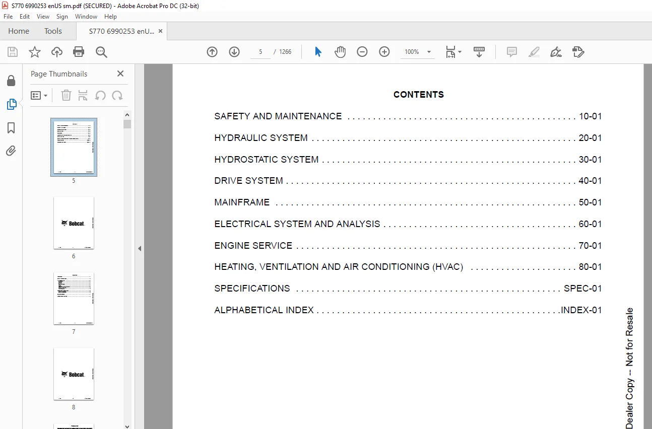
TABLE OF CONTENTS:
Bobcat S770 Compact Track Loader Service Manual 6990253 – PDF DOWNLOAD
MAINTENANCE SAFETY 3
CONTENTS 5
FOREWORD 7
FOREWORD 9
SAFETY INSTRUCTIONS 11
FIRE PREVENTION 13
Maintenance 13
Operation 13
Electrical 13
Hydraulic System 13
Fueling 13
Starting 13
Spark Arrester Exhaust System 13
Welding And Grinding 14
Fire Extinguishers 14
SERIAL NUMBER LOCATIONS 15
Loader Serial Number 15
Engine Serial Number 15
DELIVERY REPORT 16
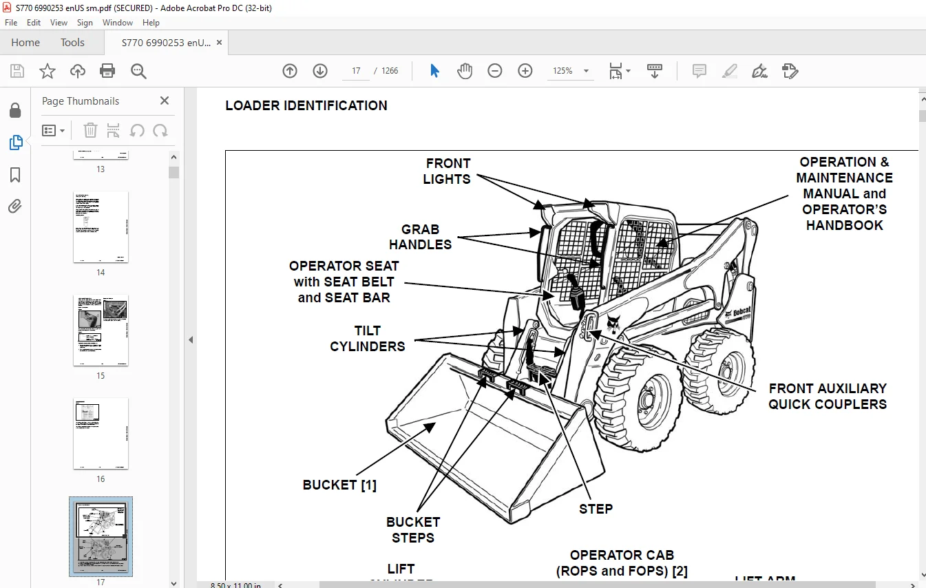
LOADER IDENTIFICATION 17
SAFETY AND MAINTENANCE 19
LIFTING AND BLOCKING THE LOADER 23
Procedure 23
LIFT ARM SUPPORT DEVICE 25
Description 25
Installing 25
Removing 26
OPERATOR CAB 27
Description 27
Raising 28
Lowering 29
Cab Door Sensor 30
Special Applications Kit 31
Special Applications Kit Inspection And Maintenance 31
Forestry Door And Window Kit 32
Forestry Door And Window Kit Inspection And Maintenance 32
TRANSPORTING THE LOADER ON A TRAILER 33
Loading And Unloading 33
Fastening 33
TOWING THE LOADER 35
Procedure 35
REMOTE START TOOL KIT – MEL1563 37
Remote Start Tool – MEL1563 37
Service Tool Harness Communicator – MEL1566 39
Remote Start Procedure 39
REMOTE START TOOL (SERVICE TOOL) KIT – 7217666 43
Description 43
Remote Start Tool (Service Tool) – 7022042 44
Loader Service Tool Harness – 6689747 45
Computer Service Tool Harness – 6689746 46
Remote Start Procedure 47
DIAGMASTER (SERVICE TOOL) KIT – 7024161 51
Diagmaster (Service Tool) 51
DST-i LED Table 52
DST-i Operation Status And Display Specification 52
Diagmaster (Service Tool) Procedure 53
SERVICE SCHEDULE 57
Maintenance Intervals 57
ENGINE AIR CLEANER 59
Replacing Filter Elements 59
ENGINE COOLING SYSTEM 61
Maintenance Platform 61
Cleaning 61
Checking And Adding Coolant 63
Removing And Replacing Coolant 64
FUEL SYSTEM 65
Fuel Specifications 65
Biodiesel Blend Fuel 65
Filling The Fuel Tank 66
Fuel Filter 67
Removing Air From The Fuel System 68
ENGINE LUBRICATION SYSTEM 69
Checking And Adding Engine Oil 69
Engine Oil Chart 69
Removing And Replacing Oil And Filter 70
Removing And Replacing Crankcase Ventilation Filter 72
HYDRAULIC / HYDROSTATIC SYSTEM 73
Checking And Adding Fluid 73
Hydraulic / Hydrostatic Fluid Chart 73
Removing And Replacing Hydraulic Fluid 74
Removing And Replacing Hydraulic / Hydrostatic Filter 76
Removing And Replacing Hydraulic Charge Filter 77
Replacing Reservoir Breather Cap 79
FINAL DRIVE TRANSMISSION (CHAINCASE) 81
Checking And Adding Fluid 81
Removing And Replacing Fluid 81
BOB-TACH (HAND LEVER) 83
Inspection And Maintenance 83
BOB-TACH (POWER) 85
Inspection And Maintenance 85
LUBRICATING THE LOADER 87
Lubrication Locations 87
TIRE MAINTENANCE 91
Wheel Nuts 91
Rotating 91
Mounting 92
DIESEL PARTICULATE FILTER (DPF) SYSTEM 93
Description 93
Remote Parked Regeneration 93
Service Regeneration 95
DPF Cleaning 96
PIVOT PINS 97
Inspection And Maintenance 97
LOADER STORAGE AND RETURN TO SERVICE 99
Storage 99
Return To Service 99
STOPPING THE ENGINE AND LEAVING THE LOADER 101
Procedure 101
EMERGENCY EXIT 103
Rear Window Identification 103
Rear Window Removal (Latches) 103
Rear Window Removal (Rubber Cord) 103
External Access (Rear Window With Latches) 104
External Access (Rear Window With Rubber Cord) 104
Front Door 104
SEAT BELT 107
Inspection And Maintenance 107
HYDRAULIC SYSTEM 109
HYDRAULIC / HYDROSTATIC SCHEMATICS 115
HYDRAULIC SYSTEM INFORMATION 127
Glossary Of Hydraulic / Hydrostatic Symbols 127
Troubleshooting 131
CYLINDER (LIFT) 133
Testing 133
Removal And Installation 134
Parts Identification 138
Disassembly 139
Assembly 140
CYLINDER (TILT) 145
Testing 145
Removal And Installation 146
Base End Pivot Pin Removal And Installation 148
Parts Identification (Early Models) 149
Parts Identification (Later Models) 150
Disassembly 151
Assembly 154
CYLINDER (BOB-TACH) 159
Testing 159
Removal And Installation 160
Parts Identification 161
Disassembly 162
Assembly 163
MAIN RELIEF VALVE (EARLY MODELS) 167
Description 167
Testing 168
Adjusting 170
Removal And Installation 170
MAIN RELIEF VALVE (LATER MODELS) 173
Description 173
Testing 174
Main Relief Valve Adjustment 176
Main Relief Valve Removal And Installation 176
Auxiliary Relief Valve Adjustment 177
Auxiliary Relief Valve Removal And Installation 178
HYDRAULIC CONTROL VALVE (STANDARD) (EARLY MODELS) 179
Description 179
Removal And Installation 180
Mount Bracket Removal And Installation 184
Identification Chart 185
Lift Load Check Valve Removal And Installation 186
Load Check Valve Removal And Installation (Tilt And Auxiliary) 187
Anti-Cavitation Valve Removal And Installation (Lift, Rod End) 188
Port Relief / Anti-Cavitation Valve Removal And Installation (Lift, Base End) 188
Port Relief / Anti-Cavitation Valve Removal And Installation (Tilt, Base End) 189
Port Relief / Anti-Cavitation Valve Removal And Installation (Tilt, Rod End) 189
Port Relief Valve Removal And Installation 190
Plug Removal And Installation 191
Rubber Boot Removal And Installation 192
End Cap Block Removal And Installation 193
Lift Spool And Detent Removal 194
Lift Spool And Detent Disassembly 196
Lift Spool And Detent Assembly 198
Lift Spool And Detent Installation 202
Tilt Spool Removal And Installation 205
Tilt Spool Disassembly and Assembly 206
Auxiliary Spool Removal And Installation 207
Auxiliary Solenoid Removal And Installation 209
Solenoid Removal And Installation 210
Lock Valve Removal And Installation 211
Lift Arm Bypass Orifice Removal And Installation 213
Main Relief Valve Removal And Installation 213
Check Valve Removal And Installation 214
HYDRAULIC CONTROL VALVE (STANDARD) (LATER MODELS) 215
Description 215
Removal And Installation 216
Mount Bracket Removal And Installation 220
Identification Chart 221
Lift Load Check Valve Removal And Installation 222
Load Check Valve Removal And Installation (Tilt And Auxiliary) 223
Anti-Cavitation Valve Removal And Installation (Lift, Rod End) 224
Port Relief / Anti-Cavitation Valve Removal And Installation (Lift, Base End) 224
Port Relief / Anti-Cavitation Valve Removal And Installation (Tilt, Base End) 225
Port Relief / Anti-Cavitation Valve Removal And Installation (Tilt, Rod End) 225
Port Relief Valve Removal And Installation 226
Plug Removal And Installation 228
Rubber Boot Removal And Installation 229
End Cap Block Removal And Installation 229
Lift Spool And Detent Removal 230
Lift Spool And Detent Disassembly 232
Lift Spool And Detent Assembly 234
Lift Spool And Detent Installation 236
Tilt Spool Removal And Installation 238
Tilt Spool Disassembly And Assembly 239
Auxiliary Spool Removal And Installation 240
Auxiliary Solenoid Removal And Installation 241
Solenoid Removal And Installation 242
Lock Valve Removal And Installation 243
Lift Arm Bypass Orifice Removal And Installation 245
Main Relief Valve Removal And Installation 245
Auxiliary Relief Valve Removal And Installation 246
Check Valve Removal And Installation 246
HYDRAULIC CONTROL VALVE (ACS) OR (SJC) (EARLY MODELS) 249
Description 249
Removal And Installation 249
Actuator Removal And Installation (In Loader) 254
Actuator Removal And Installation (Out Of Loader) 256
Identification Chart 259
Mount Bracket Removal And Installation 260
Lift Load Check Valve Removal And Installation 260
Load Check Valve Removal And Installation (Tilt And Auxiliary) 261
Anti-Cavitation Valve Removal And Installation (Lift, Rod End) 262
Port Relief / Anti-Cavitation Valve Removal And Installation (Lift, Base End) 262
Port Relief / Anti-Cavitation Valve Removal And Installation (Tilt, Base End) 263
Port Relief / Anti-Cavitation Valve Removal And Installation (Tilt, Rod End) 263
Port Relief Valve Removal And Installation 264
Plug Removal And Installation 265
End Cap Block Removal And Installation 266
Lift Spool Removal And Installation 266
Lift Spool Disassembly And Assembly 268
Tilt Spool Removal And Installation 270
Tilt Spool Disassembly And Assembly 271
Auxiliary Spool Removal And Installation 272
Auxiliary Solenoid Removal And Installation 273
Solenoid Removal And Installation 274
Lock Valve Removal And Installation 275
Lift Arm Bypass Orifice Removal And Installation 276
Main Relief Valve Removal And Installation 276
Check Valve Removal And Installation 277
HYDRAULIC CONTROL VALVE (ACS) OR (SJC) (LATER MODELS) 279
Description 279
Removal And Installation 279
Actuator Removal And Installation (In Loader) 284
Actuator Removal And Installation (Out Of Loader) 285
Identification Chart 288
Mount Bracket Removal And Installation 289
Lift Load Check Valve Removal And Installation 289
Load Check Valve Removal And Installation (Tilt And Auxiliary) 290
Anti-Cavitation Valve Removal And Installation (Lift, Rod End) 291
Port Relief / Anti-Cavitation Valve Removal And Installation (Lift, Base End) 291
Port Relief / Anti-Cavitation Valve Removal And Installation (Tilt, Base End) 292
Port Relief / Anti-Cavitation Valve Removal And Installation (Tilt, Rod End) 292
Port Relief Valve Removal And Installation 293
Plug Removal And Installation 295
End Cap Block Removal And Installation 296
Lift Spool Removal And Installation 296
Lift Spool Disassembly And Assembly 298
Tilt Spool Removal And Installation 299
Auxiliary Spool Removal And Installation 301
Auxiliary Solenoid Removal And Installation 302
Solenoid Removal And Installation 303
Lock Valve Removal And Installation 304
Lift Arm Bypass Orifice Removal And Installation 306
Main Relief Valve Removal And Installation 306
Auxiliary Relief Valve Removal And Installation 307
Check Valve Removal And Installation 307
LIFT ARM BYPASS CONTROL VALVE 309
Description 309
Testing 309
Removal And Installation 310
Bracket Removal And Installation 311
Disassembly And Assembly 311
HYDRAULIC PUMP 313
Description 313
Pump Test At Quick Couplers 313
Direct Pump Test (Standard Section) 314
Direct Pump Test (Charge Section) 316
Removal And Installation 318
Hydraulic Pump Startup 320
Parts Identification 321
Disassembly And Assembly 322
HYDRAULIC PUMP (HIGH FLOW) 323
Description 323
Pump Test At Quick Couplers 323
Direct Pump Test (Standard Section) 324
Direct Pump Test (Charge Section) 325
Direct Pump Test (High Flow Section) 327
High Flow Relief Valve Adjustment 329
High Flow Relief Valve Removal And Installation 330
Solenoid Removal And Installation 331
Removal And Installation 332
Hydraulic Pump Startup 334
Parts Identification 335
Disassembly And Assembly 336
HYDRAULIC / HYDROSTATIC FILTERS 337
Description 337
Housing Removal And Installation 337
HYDRAULIC FLUID RESERVOIR 339
Description 339
Removal And Installation 339
Hydraulic Fluid Screen 340
OIL COOLER 341
Description 341
Removal And Installation 342
BUCKET POSITION VALVE 343
Description 343
Solenoid Removal And Installation 343
Solenoid Testing 345
Removal And Installation 345
Disassembly And Assembly 347
REAR AUXILIARY DIVERTER VALVE 349
Description 349
Solenoid Testing 349
Removal And Installation 350
Disassembly And Assembly 351
BOB-TACH (POWER) BLOCK 357
Description 357
Removal And Installation 357
Disassembly And Assembly 359
FRONT AUXILIARY HYDRAULIC COUPLER BLOCK 369
Description 369
Removal And Installation 370
Disassembly And Assembly (FFI/FI) 370
Disassembly And Assembly (FFH/FH) 372
HYDROSTATIC SYSTEM 375
HYDROSTATIC SYSTEM INFORMATION 377
Troubleshooting 377
Description 378
HYDROSTATIC DRIVE MOTOR 379
Description 379
Removal And Installation 380
Parts Identification 382
Disassembly And Assembly 383
HYDROSTATIC DRIVE MOTOR (TWO-SPEED (S/N ATF211001 – ATF211599) 387
Description 387
Removal And Installation 387
Parts Identification 390
Disassembly 391
Assembly 397
HYDROSTATIC DRIVE MOTOR (TWO-SPEED) (S/N ATF211600 & ABOVE AND ATF311001 & ABOVE) 403
Description 403
Removal And Installation 403
Parts Identification 406
Disassembly 407
Assembly 413
HYDROSTATIC MOTOR CARRIER 419
Description 419
Removal And Installation 420
Parts Identification 421
Disassembly 422
Assembly 423
HYDROSTATIC MOTOR CARRIER (SJC) 425
Description 425
Removal And Installation 426
Parts Identification 428
Disassembly 429
Assembly 431
CHARGE PRESSURE 433
Description 433
Testing 433
Sender Removal And Installation 435
Adjusting 436
HYDROSTATIC PUMP 439
Description 439
Removal And Installation 440
Hydrostatic Pump Startup 441
Replenishing / High Pressure Relief Valve Removal And Installation 441
Parts Identification (Left Half) 442
Parts Identification (Right Half) 443
Disassembly 444
Assembly 451
HYDROSTATIC PUMP (SJC) 457
Description 457
Hydraulic Controller Removal And Installation 458
Removal And Installation 460
Hydrostatic Pump Startup 462
Parts Identification 463
High Pressure Relief And Bypass Valve 464
Charge Relief Valve 465
Disassembly 466
Inspection 475
Assembly 479
Mechanical Neutral Adjustment 489
Hydraulic Controller Neutral Adjustment 492
DRIVE BELT 495
Belt Adjustment 495
Stop Adjustment 495
Belt Replacement 495
Tensioner Pulley Removal And Installation 497
Tensioner Pulley Disassembly And Assembly 497
TWO-SPEED / BRAKE VALVE (S/N ATF211001 – ATF211599) 499
Description 499
Valve Block Removal And Installation 500
Valve Block Disassembly And Assembly 502
TWO-SPEED / BRAKE VALVE (S/N ATF211600 & ABOVE AND ATF311001 & ABOVE) 505
Description 505
Valve Block Removal And Installation 506
Valve Block Disassembly And Assembly 508
DRAIN MANIFOLD 511
Description 511
Drain Manifold Removal And Installation 511
DRIVE SYSTEM 513
BRAKE (SINGLE SPEED) 515
Description 515
Disc Removal And Installation 515
BRAKE (TWO-SPEED) 517
Description 517
DRIVE COMPONENTS 519
Description 519
Axle Seal Removal And Installation 520
Axle, Sprocket And Bearings Removal And Installation 522
Chain Removal And Installation 527
CHAINCASE 529
Description 529
Front Cover Removal And Installation 529
Center Cover Removal And Installation 530
Rear Cover Removal And Installation 531
MAINFRAME 533
SEAT BAR 537
Description 537
Removal And Installation 537
Disassembly And Assembly 538
Compression Spring Disassembly And Assembly 539
OPERATOR CAB 541
Gas Spring Removal And Installation 541
Gas Spring Bracket Disassembly And Assembly 542
Removal And Installation 542
OPERATOR SEAT 545
Removal And Installation 545
Seat Belt Removal And Installation (Retractable) 545
Seat Belt And Bracket Removal And Installation (Standard) 546
Seat Belt Bracket Removal And Installation 546
OPERATOR SEAT (SUSPENSION) 547
Removal And Installation 547
Slide Rail Removal And Installation 547
Seat Belt Removal And Installation 548
Lower Cushion Removal 548
Lower Cushion Installation 549
Back Cushion Removal And Installation 549
Shock Removal And Installation 550
3-Point Seat Belt Removal And Installation 550
BOB-TACH (HAND LEVER) 553
Description 553
Removal And Installation 553
Lever And Wedge Disassembly And Assembly 555
Pivot Pin Bushing And Seal Removal And Installation 557
BOB-TACH (POWER) 559
Description 559
Removal And Installation 559
Lever And Wedge Disassembly And Assembly 562
Pivot Pin Bushing And Seal Removal And Installation 563
LIFT ARMS 565
Stabilizer Bar Removal And Installation 565
Link Removal And Installation 566
Removal And Installation 567
REAR GRILLE 571
Removing 571
Installing 571
REAR DOOR (TAILGATE) 573
Removal And Installation 573
Striker Removal And Installation 574
Striker Disassembly And Assembly 574
Striker (Adjusting) 574
Latch Removal And Installation (Early Models) 575
Latch Removal And Installation (Later Models) 576
FUEL TANK 577
Removal And Installation 577
Fuel Level Sender Removal And Installation 579
Fuel Fill Screen Removal And Installation 579
CONTROL PEDALS AND LINKAGES 581
Description 581
Pedal Removal And Installation 581
Linkage Removal And Installation 582
Pedal (Adjusting) 584
Floor Pan Removal And Installation 584
CONTROL PEDALS AND LINKAGES (ACS) 585
Description 585
Pedal Removal And Installation 585
Linkage Removal And Installation 586
Pedal (Adjusting) 586
Floor Pan Removal And Installation 587
CONTROL PANEL 589
Description 589
Removal And Installation 590
Disassembly And Assembly 591
Linkage Removal And Installation 593
Pintle Arm Disassembly And Assembly 597
Linkage Neutral (Adjusting) 598
Linkage Travel (Adjusting) 602
Shock Removal And Installation 606
CONTROL PANEL (SJC) 607
Description 607
Removal And Installation 607
CONTROL HANDLE / LEVER 609
Description 609
Lever Removal And Installation 609
Boot Removal And Installation 610
CONTROL HANDLE / LEVER (ACS) 611
Description 611
Handle Sensor Removal And Installation 611
Handle Removal And Installation 614
Handle Disassembly And Assembly 615
Lever Removal And Installation 615
Boot Removal And Installation 616
CONTROL HANDLE / LEVER (SJC) 617
Description 617
Joystick Testing 617
Joystick Removal And Installation 618
ACCESS PANEL (INSIDE) 619
Removal And Installation (Left) 619
Removal And Installation (Right) 619
ACCESS PANEL (INSIDE) (SJC) 621
Removal And Installation (Left) 621
Removal And Installation (Right) 621
WINDOW (REAR) 623
Removal And Installation 623
Disassembly And Assembly 623
WINDOW (TOP) 625
Removal And Installation 625
WINDOW (SIDE) 627
Removal And Installation 627
CAB DOOR 629
Description 629
Removal And Installation 629
Disassembly And Assembly 630
Aligning 631
Adjusting 632
Checking Operation 632
ARMREST 633
Description 633
Removal And Installation 634
Disassembly And Assembly 635
LEFT SIDE LOWER PANEL 637
Removal And Installation 637
Disassembly And Assembly 639
RIGHT SIDE LOWER PANEL 641
Removal And Installation 641
Disassembly And Assembly 642
HEADLINER 645
Removal And Installation 645
ELECTRICAL SYSTEM AND ANALYSIS 647
ELECTRICAL SCHEMATICS 653
ELECTRICAL SYSTEM INFORMATION 849
Glossary Of Electrical Symbols 849
Standard Cab Harness Connectors 852
Deluxe Cab Harness Connectors 853
Mainframe Harness Connectors 854
Engine Harness Connectors 855
Description 856
Troubleshooting 857
Fuse And Relay Location / Identification 858
Solenoid Testing 861
BATTERY 863
Removal And Installation 863
Servicing 864
Using A Booster Battery (Jump Starting) 865
ALTERNATOR 867
Belt Adjustment 867
Belt Replacement 867
Charging System Inspection 868
Alternator Voltage Testing 869
Low Voltage Testing 869
High Voltage Testing 870
Removal And Installation 871
Parts Identification 873
STARTER 875
Testing 875
Removal And Installation 875
Parts Identification 876
INSTRUMENT PANELS 877
Left Panel 877
Display Screen 879
Right Panel (Standard Key Panel) 880
Right Panel (Keyless Start Panel) 881
Right Panel (Deluxe Instrumentation Panel) 882
Left Switch Panel 884
Right Switch Panel 884
Left Side Lower Panel 885
Right Side Lower Panel 885
Left Panel Removal And Installation 886
Right Panel (Standard Key Panel) Removal And Installation 886
Right Panel (Keyless Start Panel) Removal And Installation 887
Right Panel (Deluxe Instrumentation Panel) Removal And Installation 887
Key Switch Disassembly And Assembly 888
Alarm Disassembly And Assembly 888
Left Switch Panel Removal And Installation 889
Right Switch Panel Removal And Installation 889
LIGHTS 891
Front Removal And Installation 891
Rear Removal And Installation 892
Cab Light Removal And Installation (Early Models) 892
Cab Light Removal And Installation (Later Models) 893
BOBCAT CONTROLLERS (GATEWAY AND AUXILIARY) 895
Description 895
Connector Identification 896
Removal And Installation 902
BOBCAT CONTROLLER (ACS) 903
Description 903
Connector And Wire Identification 904
Removal And Installation 905
BOBCAT CONTROLLER (SJC) (DRIVE) 907
Description 907
Connector Identification 908
Removal And Installation 910
ENGINE CONTROL UNIT (ECU) 911
Description 911
Cleaning 912
Removal And Installation 913
DIAGNOSTIC SERVICE CODES 915
Viewing Service Codes 915
Service Codes List 916
DIAGMASTER DIAGNOSTIC TROUBLE CODES (DCT) 923
Viewing Trouble Codes 923
BOBCAT INTERLOCK CONTROL SYSTEM (BICS™) 925
Description 925
Operation 925
Inspecting The BICS™ (Engine STOPPED – Key ON) 926
Inspecting Deactivation Of The Auxiliary Hydraulics System (Engine STOPPED – Key ON) 926
Inspecting The Seat Bar Sensor (Engine RUNNING) 926
Inspecting The Traction Lock (Engine RUNNING) 926
Inspecting The Lift Arm Bypass Control 926
Inspecting Deactivation Of Lift And Tilt Functions (ACS And SJC) 926
Troubleshooting 927
SEAT BAR SENSOR 929
Description 929
Troubleshooting 929
Testing 930
Removal 931
Installation 932
Bobcat Interlock Control System (BICS™) Circuit Test 934
TRACTION LOCK 937
Description 937
Troubleshooting 938
Inspecting 939
CONTROL SYSTEM (ACS) 941
Description 941
Troubleshooting 942
Handle Sensor Connector Disassembly And Assembly 943
Switch Handle Removal 944
Switch Handle Installation 946
Actuator Connector Disassembly And Assembly 949
Handle Lock Solenoid Removal And Installation 950
Handle Lock Solenoid Disassembly And Assembly 950
Foot Sensor Removal And Installation 951
Foot Sensor Disassembly And Assembly 952
Foot Sensor Lock Solenoid Removal And Installation 952
ELECTRICAL / HYDRAULIC CONTROLS 953
Identification Chart 953
Description 954
Identification Chart ACD Group 0 955
Identification Chart ACD Group 1 956
Identification Chart ACD Group 2 957
Identification Chart ACD Group 3 958
ELECTRICAL / HYDRAULIC CONTROLS (ACS) 959
Identification Chart 959
Description 960
Identification Chart ACD Group 0 961
Identification Chart ACD Group 1 962
Identification Chart ACD Group 2 963
Identification Chart ACD Group 3 964
ELECTRICAL / HYDRAULIC CONTROLS (SJC) 965
Identification Chart 965
Description 966
Identification Chart ACD Group 0 967
Identification Chart ACD Group 1 968
Identification Chart ACD Group 2 969
Identification Chart ACD Group 3 970
SERVICE PC (LAPTOP COMPUTER) 971
Connecting Remote Start Tool 971
Connecting Remote Start Tool (Service Tool) 971
Connecting Diagmaster (Service Tool) 972
Connecting Remote Parked Regeneration Kit 972
CALIBRATION 973
Description 973
Actuator Testing 973
Lift And Tilt Calibration (SJC) 976
Hydrostatic Pump Calibration (SJC) 978
Lift And Tilt Calibration (ACS) 983
STEERING DRIFT COMPENSATION (OPERATOR MODE) 985
Description 985
Operation 985
STEERING DRIFT COMPENSATION (SERVICE MODE) 987
Description 987
Operation 987
CONTROL PANEL SETUP 989
Right Panel Setup (Deluxe Instrumentation Panel) 989
PASSWORD SETUP (DELUXE INSTRUMENTATION PANEL) 993
Password Description 993
Changing The Owner Password 993
Changing The User Passwords 994
Password Lockout Feature 994
PASSWORD SETUP (KEYLESS START PANEL) 995
Password Description 995
Changing The Owner Password 995
Password Lockout Feature 995
MAINTENANCE CLOCK 997
Description 997
Setup 998
Reset 1001
BACK-UP ALARM SYSTEM 1003
Description 1003
Inspection 1003
Adjusting Switch Position 1004
Troubleshooting (Standard And ACS) 1005
Troubleshooting (Joystick) 1006
Alarm Removal And Installation 1007
Switch Removal And Installation 1007
FRONT HORN 1009
Removal And Installation 1009
Troubleshooting 1010
Troubleshooting (Joystick) 1011
ENGINE SERVICE 1013
ENGINE INFORMATION 1017
Description 1017
Specifications 1018
Sensor Location 1021
Torque Values 1024
Troubleshooting 1025
Engine Removal And Installation 1026
Engine Mount Replacement 1039
Compression – Testing 1041
ENGINE SPEED CONTROL (HAND) 1045
Removal And Installation 1045
ENGINE SPEED CONTROL (FOOT) 1047
Removal And Installation 1047
Disassembly And Assembly 1048
DIESEL PARTICULATE FILTER (DPF) SYSTEM 1051
Description 1051
Removal And Installation 1052
DPF Regeneration 1055
DPF Regeneration Table 1055
Operation (Standard Switch) 1056
Operation (Optional Inhibit Switch Kit) 1057
Operation (Optional Remote Parked Regeneration Kit) 1058
Remote Parked Regeneration (Level 3) 1058
DPF Service Regeneration (Level 4) 1060
DPF Cleaning (Level 5) 1063
AIR CLEANER 1065
Housing Removal And Installation 1065
ENGINE COOLING SYSTEM (EARLY MODELS) 1067
Radiator Removal And Installation 1067
Hydraulic Fan Description 1068
Fan Duct Removal And Installation 1069
Hydraulic Fan Motor Assembly Removal And Installation 1069
Hydraulic Fan Motor Removal And Installation 1070
Hydraulic Fan Motor Disassembly And Assembly 1071
Blower Housing Removal And Installation 1073
Water Pump Removal And Installation 1073
Water Pump Disassembly And Assembly 1074
Thermostat Housing Removal And Installation 1074
Thermostat – Testing 1075
ENGINE COOLING SYSTEM (LATER MODELS) 1077
Radiator Removal And Installation 1077
Hydraulic Fan Description 1078
Fan Duct Removal And Installation 1079
Hydraulic Fan Motor Assembly Removal And Installation 1079
Hydraulic Fan Motor Removal And Installation 1080
Hydraulic Fan Motor Disassembly And Assembly 1082
Blower Housing Removal And Installation 1087
Water Pump Removal And Installation 1088
Water Pump Disassembly And Assembly 1088
Thermostat Housing Removal And Installation 1089
Thermostat – Testing 1089
LUBRICATION SYSTEM 1091
Oil Pan Removal And Installation 1091
Oil Pump Removal And Installation 1092
Oil Pump Inspection 1092
Oil Filter Cooler Removal And Installation 1094
Engine Oil Pressure – Testing 1095
Crankcase Ventilation Filter Removal And Installation 1096
FUEL SYSTEM 1097
Supply Pump Removal 1097
Supply Pump Installation 1100
Supply Pump Difference Learning 1102
Fuel Rail Assembly Removal And Installation 1104
Supply Pump – Timing 1105
Fuel Injector Removal And Installation 1106
Injector Correction 1110
CYLINDER HEAD 1111
Intake Air Heater – Testing 1111
Intake Air Heater Removal And Installation 1111
Valve Clearance Adjustment 1113
Cylinder Head Removal And Installation 1114
Cylinder Head Disassembly And Assembly 1116
Cylinder Head – Servicing 1116
Cylinder Head Top Clearance 1116
Valve Guide – Inspecting 1117
Reconditioning The Valve And Valve Seat 1119
Valve Spring 1121
Valve Tappets 1122
Rocker Arm And Shaft – Inspecting 1123
Valve Bridge Arm And Shaft – Inspecting 1124
Push Rod Alignment – Inspecting 1124
CRANKSHAFT AND PISTONS 1125
Piston And Connecting Rod Removal And Installation 1125
Piston And Connecting Rod – Servicing 1127
Cylinder Bore – Measuring 1131
Connecting Rod Alignment 1132
Crankshaft Gear Removal And Installation 1132
Crankshaft And Bearings Removal 1133
Crankshaft And Bearings Installation 1135
Crankshaft And Bearings – Servicing 1137
CRANKSHAFT POSITION SENSOR 1143
Description 1143
Removal And Installation 1143
Adjusting 1144
CAMSHAFT AND TIMING GEARS 1147
Timing Gearcase Cover Removal And Installation 1147
Timing Gears Backlash – Measuring 1148
Idler Gear And Camshaft Removal And Installation 1148
Camshaft – Servicing 1149
Idler Gear And Shaft – Servicing 1151
TURBOCHARGER 1155
Description 1155
Removal And Installation 1156
Testing 1158
EGR Cooler Testing 1159
FLYWHEEL AND HOUSING 1161
Flywheel Removal And Installation 1161
Ring Gear Removal And Installation 1161
Housing Removal And Installation 1162
EXHAUST GAS RECIRCULATION (EGR) SYSTEM 1163
Description 1163
Testing 1164
Removal And Installation 1166
HEATING, VENTILATION AND AIR CONDITIONING (HVAC) 1167
AIR CONDITIONING SYSTEM FLOW 1169
Description 1169
Chart 1170
Components 1171
Safety Equipment 1174
REGULAR MAINTENANCE 1175
Filters 1175
Compressor Drive Belt Adjustment 1176
Compressor Drive Belt Replacement 1176
Condenser 1176
Air Conditioning Lubrication 1176
Air Conditioning Service Chart 1177
Evaporator / Heater Coil 1178
TROUBLESHOOTING 1179
Blower Motor Does Not Operate 1179
Blower Motor Operates Normally, But Air Flow Is Insufficient 1179
Insufficient Cooling Although Air Flow And Compressor Operation Are Normal 1179
The Compressor Does Not Operate At All, Or Operates Improperly 1179
Gauge Pressure Related Troubleshooting 1180
Troubleshooting Tree 1182
Temperature / Pressure Chart 1185
Poor A/C Performance 1187
HVAC Repair And Leaks 1188
Electrical System 1189
Engine Coolant Bypassing The Heater Valve 1195
Heater Valve Not Opening Or Closing 1196
SYSTEM CHARGING AND RECLAMATION 1197
Refrigerant Identification 1197
Reclamation And Charging With Recovery / Charging Unit 1198
COMPRESSOR 1201
Removal And Installation 1201
Oil 1203
Oil Check 1204
CONDENSER 1205
Removal And Installation 1205
RECEIVER / DRIER 1207
Receiver / Drier Removal And Installation 1207
Pressure Relief Valve Removal And Installation 1208
Pressure Switch Removal And Installation 1209
Schrader® Valve Removal And Installation 1210
EVAPORATOR / HEATER UNIT 1211
Removal And Installation 1211
THERMOSTAT 1213
Description 1213
Removal And Installation 1214
EXPANSION VALVE 1215
Removal And Installation 1215
EVAPORATOR COIL 1217
Removal And Installation 1217
HEATER COIL 1219
Removal And Installation 1219
BLOWER FAN 1221
Removal And Installation 1221
Disassembly And Assembly 1221
HEATER VALVE 1225
Removal And Installation 1225
EVAPORATOR / HEATER COVER 1227
Removing 1227
Installing 1227
SPECIFICATIONS 1229
(S770) LOADER SPECIFICATIONS 1231
Machine Dimensions 1231
Performance 1232
Engine 1232
Drive System 1233
Controls 1233
Hydraulic System 1234
Electrical System 1235
Capacities 1235
Tires 1236
TECHINCAL SERVICE GUIDE SPECIFICATIONS 1237
Engine 1237
Engine Torques 1237
Cooling System 1237
Loader Torques 1238
Hydraulic / Hydrostatic System 1238
Fuel Consumption 1238
TORQUE SPECIFICATIONS FOR BOLTS 1239
Torque For General SAE Bolts 1239
Torque For General Metric Bolts 1240
HYDRAULIC CONNECTION SPECIFICATIONS 1241
Straight Thread O-ring Fitting 1241
Flare Fitting 1242
Tubelines And Hoses 1242
HYDRAULIC / HYDROSTATIC FLUID SPECIFICATIONS 1243
Specifications 1243
CONVERSIONS 1245
Decimal And Millimeter Equivalent Chart 1245
U S To Metric Conversion Chart 1245
SERVICE TOOLS REQUIRED 1247
Remote Start Tools 1247
Hydraulic Tools 1248
Mainframe And Drive Tools 1251
Electrical Tools 1254
Engine Tools 1255
HVAC Tools 1260
ALPHABETICAL INDEX 1261
Contact us: [email protected]
PLEASE NOTE:
- This is the same manual used by the dealers to diagnose and troubleshoot your vehicle
- You will be directed to the download page as soon as the purchase is completed. The whole payment and downloading process will take anywhere between 2-5 minutes
- Need any other service / repair / parts manual, please feel free to contact [email protected] . We still have 50,000 manuals unlisted
S.V


