Bobcat S770 Skid-Steer Loader Service Manual 6989468 – PDF DOWNLOAD
$33.95
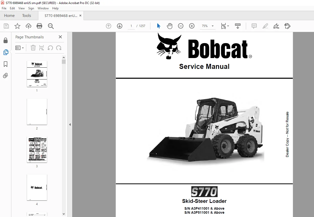
Bobcat S770 Skid-Steer Loader Service Manual 6989468 – PDF DOWNLOAD
S/N A3P411001 & Above
S/N A3P511001 & Above
Description
Bobcat S770 Skid-Steer Loader Service Manual 6989468 – PDF DOWNLOAD
FILE DETAILS:
Bobcat S770 Skid-Steer Loader Service Manual 6989468 – PDF DOWNLOAD
Language : English
Pages : 1257
Downloadable : Yes
File Type : PDF
DESCRIPTION:
Bobcat S770 Skid-Steer Loader Service Manual 6989468 – PDF DOWNLOAD
S/N A3P411001 & Above
S/N A3P511001 & Above
FOREWORD:
This manual is for the Bobcat loader mechanic. It provides necessary servicing and adjustment procedures for the Bobcat loader and its component parts and systems. Refer to the Operation & Maintenance Manual for operating instructions, starting procedure, daily checks, etc.
A general inspection of the following items must be made after the loader has had service or repair:
TABLE OF CONTENTS:
Bobcat S770 Skid-Steer Loader Service Manual 6989468 – PDF DOWNLOAD
MAINTENANCE SAFETY 3
CONTENTS 5
FOREWORD 7
FOREWORD 9
SAFETY INSTRUCTIONS 11
FIRE PREVENTION 13
Maintenance 13
Operation 13
Electrical 13
Hydraulic System 13
Fueling 13
Starting 13
Spark Arrester Exhaust System 13
Welding And Grinding 14
Fire Extinguishers 14
SERIAL NUMBER LOCATIONS 15
Loader Serial Number 15
Engine Serial Number 15
DELIVERY REPORT 16
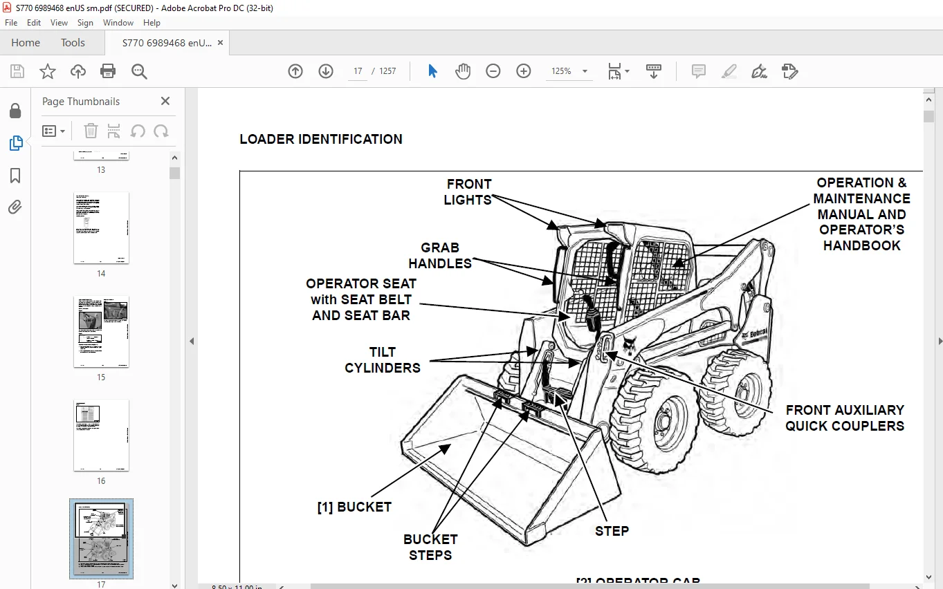
LOADER IDENTIFICATION 17
SAFETY & MAINTENANCE 19
LIFTING AND BLOCKING THE LOADER 23
Procedure 23
LIFT ARM SUPPORT DEVICE 25
Installing 25
Removing 26
OPERATOR CAB 27
Description 27
Raising 28
Lowering 29
Cab Door Sensor 30
Special Applications Kit 31
Special Applications Kit Inspection And Maintenance 31
Forestry Door And Window Kit 32
Forestry Door And Window Kit Inspection And Maintenance 32
TRANSPORTING LOADER ON A TRAILER 33
Loading And Unloading 33
Fastening 33
TOWING THE LOADER 35
Procedure 35
REMOTE START TOOL KIT – MEL1563 37
Remote Start Tool – MEL1563 37
Service Tool Harness Communicator – MEL1566 39
Remote Start Procedure 39
REMOTE START TOOL (SERVICE TOOL) KIT – 7217666 43
Description 43
Remote Start Tool (Service Tool) – 7022042 44
Loader Service Tool Harness – 6689747 45
Computer Service Tool Harness – 6689746 46
Remote Start Procedure 47
SERVICE SCHEDULE 51
Chart 51
AIR CLEANER SERVICE 53
Replacing Filter Elements 53
ENGINE COOLING SYSTEM 55
Maintenance Platform 55
Cleaning 55
Checking Level 57
Removing And Replacing Coolant 57
FUEL SYSTEM 59
Fuel Specifications 59
Biodiesel Blend Fuel 59
Filling The Fuel Tank 60
Fuel Filter 61
Removing Air From The Fuel System 61
ENGINE LUBRICATION SYSTEM 63
Checking And Adding Engine Oil 63
Engine Oil Chart 63
Removing And Replacing Oil And Filter 64
HYDRAULIC / HYDROSTATIC SYSTEM 67
Checking And Adding Fluid 67
Hydraulic / Hydrostatic Fluid Chart 67
Removing And Replacing Hydraulic Fluid 68
Removing And Replacing Hydraulic / Hydrostatic Filter 70
Removing And Replacing Hydraulic Charge Filter 71
FINAL DRIVE TRANSMISSION (CHAINCASE) 73
Checking And Adding Fluid 73
Removing And Replacing Fluid 73
BOB-TACH (HAND LEVER) 75
Inspection And Maintenance 75
BOB-TACH (POWER) 77
Inspection And Maintenance 77
LUBRICATING THE LOADER 79
Lubrication Locations 79
TIRE MAINTENANCE 83
Wheel Nuts 83
Rotating 83
Mounting 84
SPARK ARRESTER MUFFLER 85
Cleaning Procedure 85
PIVOT PINS 87
Inspection And Maintenance 87
LOADER STORAGE AND RETURN TO SERVICE 89
Storage 89
Return To Service 89
STOPPING THE ENGINE AND LEAVING THE LOADER 91
Procedure 91
EMERGENCY EXIT 93
Rear Window Identification 93
Rear Window Removal (Latches) 93
Rear Window Removal (Rubber Cord) 93
External Access (Rear Window With Latches) 94
External Access (Rear Window With Rubber Cord) 94
Front Door 95
SEAT BELT 97
Inspection And Maintenance 97
HYDRAULIC SYSTEM 99
HYDRAULIC / HYDROSTATIC SCHEMATICS 105
HYDRAULIC SYSTEM INFORMATION 121
Glossary Of Hydraulic / Hydrostatic Symbols 121
Troubleshooting 125
CYLINDER (LIFT) 127
Testing 127
Removal And Installation 128
Parts Identification 132
Disassembly 133
Assembly 134
CYLINDER (TILT) 137
Testing 137
Removal And Installation 138
Base End Pivot Pin Removal And Installation 140
Parts Identification (Earlier Models) 141
Parts Identification (Later Models) 142
Disassembly 143
Assembly 146
CYLINDER (BOB-TACH) 151
Testing 151
Removal And Installation 152
Parts Identification 153
Disassembly 154
Assembly 155
MAIN RELIEF VALVE (EARLIER MODELS) 159
Description 159
Testing 160
Adjusting 162
Removal And Installation 162
MAIN RELIEF VALVE (LATER MODELS) 165
Description 165
Testing 166
Main Relief Valve Adjustment 168
Main Relief Valve Removal And Installation 168
Auxiliary Relief Valve Adjustment 169
Auxiliary Relief Valve Removal And Installation 170
HYDRAULIC CONTROL VALVE (STANDARD) (EARLIER MODELS) 171
Description 171
Removal And Installation 172
Mount Bracket Removal And Installation 176
Identification Chart 177
Lift Load Check Valve Removal And Installation 178
Load Check Valve Removal And Installation (Tilt And Auxiliary) 179
Anti-Cavitation Valve Removal And Installation (Lift, Rod End) 180
Port Relief / Anti-Cavitation Valve Removal And Installation (Lift, Base End) 180
Port Relief / Anti-Cavitation Valve Removal And Installation (Tilt, Base End) 181
Port Relief / Anti-Cavitation Valve Removal And Installation (Tilt, Rod End) 181
Port Relief Valve Removal And Installation 182
Plug Removal And Installation 183
Rubber Boot Removal And Installation 184
End Cap Block Removal And Installation 185
Lift Spool And Detent Removal And Installation 186
Tilt Spool Removal And Installation 196
Auxiliary Spool Removal And Installation 198
Auxiliary Solenoid Removal And Installation 199
Solenoid Removal And Installation 200
Lock Valve Removal And Installation 201
Lift Arm Bypass Orifice Removal And Installation 203
Main Relief Valve Removal And Installation 203
Check Valve Removal And Installation 204
HYDRAULIC CONTROL VALVE (STANDARD) (LATER MODELS) 205
Description 205
Removal And Installation 206
Mount Bracket Removal And Installation 210
Identification Chart 211
Lift Load Check Valve Removal And Installation 212
Load Check Valve Removal And Installation (Tilt And Auxiliary) 213
Anti-Cavitation Valve Removal And Installation (Lift, Rod End) 214
Port Relief / Anti-Cavitation Valve Removal And Installation (Lift, Base End) 214
Port Relief / Anti-Cavitation Valve Removal And Installation (Tilt, Base End) 215
Port Relief / Anti-Cavitation Valve Removal And Installation (Tilt, Rod End) 215
Port Relief Valve Removal And Installation 216
Plug Removal And Installation 218
Rubber Boot Removal And Installation 219
End Cap Block Removal And Installation 219
Lift Spool And Detent Removal And Installation 220
Tilt Spool Removal And Installation 228
Auxiliary Spool Removal And Installation 230
Auxiliary Solenoid Removal And Installation 231
Solenoid Removal And Installation 232
Lock Valve Removal And Installation 233
Lift Arm Bypass Orifice Removal And Installation 235
Main Relief Valve Removal And Installation 235
Auxiliary Relief Valve Removal And Installation 236
Check Valve Removal And Installation 236
HYDRAULIC CONTROL VALVE (ACS) OR (SJC) (EARLIER MODELS) 239
Description 239
Removal And Installation 239
Actuator Removal And Installation (In Loader) 244
Actuator Removal And Installation (Out Of Loader) 245
Identification Chart 248
Mount Bracket Removal And Installation 249
Lift Load Check Valve Removal And Installation 249
Lo22d Check Valve Removal And Installation (Tilt And Auxiliary) 250
Anti-Cavitation Valve Removal And Installation (Lift, Rod End) 251
Port Relief / Anti-Cavitation Valve Removal And Installation (Lift, Base End) 251
Port Relief / Anti-Cavitation Valve Removal And Installation (Tilt, Base End) 252
Port Relief / Anti-Cavitation Valve Removal And Installation (Tilt, Rod End) 252
Port Relief Valve Removal And Installation 253
Plug Removal And Installation 254
End Cap Block Removal And Installation 255
Lift Spool Removal And Installation 255
Lift Spool Disassembly And Assembly 257
Tilt Spool Removal And Installation 259
Auxiliary Spool Removal And Installation 261
Auxiliary Solenoid Removal And Installation 262
Solenoid Removal And Installation 263
Lock Valve Removal And Installation 264
Lift Arm Bypass Orifice Removal And Installation 265
Main Relief Valve Removal And Installation 265
Check Valve Removal And Installation 266
HYDRAULIC CONTROL VALVE (ACS) OR (SJC) (LATER MODELS) 267
Description 267
Removal And Installation 267
Actuator Removal And Installation (In Loader) 272
Actuator Removal And Installation (Out Of Loader) 273
Identification Chart 276
Mount Bracket Removal And Installation 277
Lift Load Check Valve Removal And Installation 277
Load Check Valve Removal And Installation (Tilt And Auxiliary) 278
Anti-Cavitation Valve Removal And Installation (Lift, Rod End) 279
Port Relief / Anti-Cavitation Valve Removal And Installation (Lift, Base End) 279
Port Relief / Anti-Cavitation Valve Removal And Installation (Tilt, Base End) 280
Port Relief / Anti-Cavitation Valve Removal And Installation (Tilt, Rod End) 280
Port Relief Valve Removal And Installation 281
Plug Removal And Installation 283
End Cap Block Removal And Installation 284
Lift Spool Removal And Installation 284
Lift Spool Disassembly And Assembly 286
Tilt Spool Removal And Installation 287
Auxiliary Spool Removal And Installation 289
Auxiliary Solenoid Removal And Installation 290
Solenoid Removal And Installation 291
Lock Valve Removal And Installation 292
Lift Arm Bypass Orifice Removal And Installation 294
Main Relief Valve Removal And Installation 294
Auxiliary Relief Valve Removal And Installation 295
Check Valve Removal And Installation 295
LIFT ARM BYPASS CONTROL VALVE 297
Description 297
Testing 297
Removal And Installation 298
Bracket Removal And Installation 299
Disassembly And Assembly 299
HYDRAULIC PUMP 301
Description 301
Pump Test At Quick Couplers 301
Direct Pump Test (Standard Section) 302
Direct Pump Test (Charge Section) 304
Removal And Installation 306
Hydraulic Pump Startup 308
Parts Identification 309
Disassembly And Assembly 310
HYDRAULIC PUMP (HIGH FLOW) 311
Description 311
Pump Test At Quick Couplers 311
Direct Pump Test (Standard Section) 312
Direct Pump Test (Charge Section) 313
Direct Pump Test (High Flow Section) 315
High Flow Relief Valve Adjustment 317
High Flow Relief Valve Removal And Installation 318
Solenoid Removal And Installation 319
Removal And Installation 320
Hydraulic Pump Startup 322
Parts Identification 323
Disassembly And Assembly 324
HYDRAULIC / HYDROSTATIC FILTERS 325
Description 325
Housing Removal And Installation 325
HYDRAULIC FLUID RESERVOIR 327
Description 327
Removal And Installation 327
Hydraulic Fluid Screen 328
OIL COOLER 329
Description 329
Removal And Installation 329
BUCKET POSITION VALVE 331
Description 331
Solenoid Removal And Installation 331
Solenoid Testing 333
Removal And Installation 333
Disassembly And Assembly 335
REAR AUXILIARY DIVERTER VALVE 337
Description 337
Solenoid Testing 337
Removal And Installation 338
Disassembly And Assembly 339
BOB-TACH (POWER) BLOCK (S/N A3P411001 – A3P413656 AND A3P511001 – A3P512980) 345
Description 345
Removal And Installation 345
Disassembly And Assembly 347
BOB-TACH (POWER) BLOCK (S/N A3P413657 AND A3P512981 & ABOVE) 355
Description 355
Testing Relief Valve 356
Removal And Installation 358
Disassembly And Assembly 360
FRONT AUXILIARY HYDRAULIC COUPLER BLOCK 365
Description 365
Removal And Installation 366
Disassembly And Assembly (FFI/FI) 366
Disassembly And Assembly (FFH/FH) 368
AUTOMATIC RIDE CONTROL 371
Description 371
Removal And Installation 372
Checking The Pressure In The Accumulator 375
Adding Nitrogen To The Accumulator 377
HYDROSTATIC SYSTEM 379
HYDROSTATIC SYSTEM INFORMATION 383
Troubleshooting 383
Description 384
HYDROSTATIC DRIVE MOTOR 385
Description 385
Removal And Installation 386
Parts Identification 388
Disassembly And Assembly 389
HYDROSTATIC DRIVE MOTOR (TWO-SPEED) (S/N A3P411001 – A3P12849 AND A3P511001 – A3P12124) 393
Description 393
Removal And Installation 393
Parts Identification 396
Disassembly 397
Assembly 403
HYDROSTATIC DRIVE MOTOR (TWO-SPEED) (S/N A3P412850 & ABOVE AND A3P512125 & ABOVE) 409
Description 409
Removal And Installation 409
Parts Identification 412
Disassembly 413
Assembly 419
HYDROSTATIC MOTOR CARRIER 425
Description 425
Removal And Installation 426
Parts Identification 427
Disassembly 428
Assembly 429
HYDROSTATIC MOTOR CARRIER (SJC) 433
Description 433
Removal And Installation 434
Parts Identification 435
Disassembly 436
Assembly 438
CHARGE PRESSURE (EARLIER MODELS) 441
Description 441
Testing 441
Sender Removal And Installation 443
Adjusting 444
CHARGE PRESSURE (LATER MODELS) 447
Description 447
Testing 447
Sender Removal And Installation 449
Adjusting 450
HYDROSTATIC PUMP 451
Description 451
Removal And Installation 452
Hydrostatic Pump Startup 453
Replenishing / High Pressure Relief Valve Removal And Installation 454
Parts Identification (Left Half) 455
Parts Identification (Right Half) 456
Disassembly 457
Assembly 464
HYDROSTATIC PUMP (SJC) 471
Description 471
Hydraulic Controller Removal And Installation 472
Removal And Installation 473
Hydrostatic Pump Startup 475
Parts Identification 476
High Pressure Relief And Bypass Valve 477
Charge Relief Valve 478
Disassembly 479
Inspection 487
Assembly 491
Mechanical Neutral Adjustment 499
Hydraulic Controller Neutral Adjustment 502
DRIVE BELT 505
Belt Adjustment 505
Stop Adjustment 505
Belt Replacement 505
Tensioner Pulley Removal And Installation 507
Tensioner Pulley Disassembly And Assembly 507
TWO-SPEED / BRAKE VALVE (S/N A3P411001 – A3P412849 AND A3P511001 – A3P512124) 509
Description 509
Valve Block Removal And Installation 509
Valve Block Disassembly And Assembly 511
TWO-SPEED / BRAKE VALVE (S/N A3P412850 & ABOVE AND A3P512125 & ABOVE) 515
Description 515
Valve Block Removal And Installation 515
Valve Block Disassembly And Assembly 517
DRAIN MANIFOLD 521
Description 521
Drain Manifold Removal And Installation 521
DRIVE SYSTEM 523
BRAKE (SINGLE SPEED) 525
Description 525
Disc Removal And Installation 525
BRAKE (TWO-SPEED) 527
Description 527
DRIVE COMPONENTS 529
Description 529
Axle Seal Removal And Installation 530
Axle, Sprocket And Bearings Removal And Installation 532
Chain Removal And Installation 536
CHAINCASE 539
Description 539
Front Cover Removal And Installation 539
Center Cover Removal And Installation 540
Rear Cover Removal And Installation 541
MAINFRAME 543
SEAT BAR 547
Description 547
Removal And Installation 547
Disassembly And Assembly 548
Compression Spring Disassembly And Assembly 549
OPERATOR CAB 551
Gas Spring Removal And Installation 551
Gas Spring Bracket Disassembly And Assembly 552
Removal And Installation 552
OPERATOR SEAT 555
Removal And Installation 555
Seat Belt Removal And Installation (Retractable) 555
Seat Belt And Bracket Removal And Installation (Standard) 556
Seat Belt Bracket Removal And Installation (Standard) 556
OPERATOR SEAT (SUSPENSION) 557
Removal And Installation 557
Slide Rail Removal And Installation 557
Seat Belt Removal And Installation 558
Lower Cushion Removal 558
Lower Cushion Installation 559
Back Cushion Removal And Installation 559
Shock Removal And Installation 560
3-Point Seat Belt Removal And Installation 560
BOB-TACH (HAND LEVER) 563
Description 563
Removal And Installation 563
Lever And Wedge Disassembly And Assembly 565
Pivot Pin Bushing And Seal Removal And Installation 567
BOB-TACH (POWER) 569
Description 569
Removal And Installation 569
Lever And Wedge Disassembly And Assembly 572
Pivot Pin Bushing And Seal Removal And Installation 574
LIFT ARMS 575
Stabilizer Bar Removal And Installation 575
Link Removal And Installation 576
Removal And Installation 577
REAR GRILLE 581
Removing 581
Installing 581
REAR DOOR (TAILGATE) 583
Removal And Installation 583
Striker Removal And Installation 584
Striker Disassembly And Assembly 584
Striker (Adjusting) 584
Latch Removal And Installation (Earlier Models) 585
Latch Removal And Installation (Later Models) 586
FUEL TANK 587
Removal And Installation 587
Fuel Level Sender Removal And Installation 589
Fuel Fill Screen Removal And Installation 589
CONTROL PEDALS AND LINKAGES 591
Description 591
Pedal Removal And Installation 591
Linkage Removal And Installation 592
Pedal (Adjusting) 593
Floor Pan Removal And Installation 594
CONTROL PEDALS AND LINKAGES (ACS) 595
Description 595
Pedal Removal And Installation 595
Linkage Removal And Installation 596
Pedal (Adjusting) 596
Floor Pan Removal And Installation 597
CONTROL PANEL 599
Description 599
Removal And Installation 600
Disassembly And Assembly 602
Linkage Removal And Installation 606
Pintle Arm Disassembly And Assembly 610
Linkage Neutral (Adjusting) 611
Linkage Travel (Adjusting) 615
Shock Removal And Installation 619
CONTROL PANEL (SJC) 621
Description 621
Removal And Installation 621
CONTROL HANDLE / LEVER 623
Description 623
Lever Removal And Installation 623
Boot Removal And Installation 623
CONTROL HANDLE / LEVER (ACS) 625
Description 625
Handle Sensor Removal And Installation 625
Handle Removal And Installation 628
Handle Disassembly And Assembly 629
Lever Removal And Installation 629
Boot Removal And Installation 630
CONTROL HANDLE / LEVER (SJC) 631
Description 631
Joystick Testing 631
Joystick Removal And Installation 632
ACCESS PANEL (INSIDE) 633
Removal And Installation (Left) 633
Removal And Installation (Right) 633
ACCESS PANEL (INSIDE) (SJC) 635
Removal And Installation (Left) 635
Removal And Installation (Right) 635
WINDOW (REAR) 637
Removal And Installation 637
Disassembly And Assembly 637
WINDOW (TOP) 639
Removal And Installation 639
WINDOW (SIDE) 641
Removal And Installation 641
CAB DOOR 643
Description 643
Removal And Installation 643
Disassembly And Assembly 644
Aligning 645
Adjusting 646
Testing Operation 646
ARMREST 647
Description 647
Removal And Installation 647
Disassembly And Assembly 648
LEFT SIDE LOWER PANEL 651
Removal And Installation 651
Disassembly And Assembly 653
RIGHT SIDE LOWER PANEL 655
Removal And Installation 655
Disassembly And Assembly 656
HEADLINER 659
Removal And Installation 659
ELECTRICAL SYSTEM 661
ELECTRICAL SCHEMATICS 667
ELECTRICAL SYSTEM INFORMATION 846
Glossary Of Electrical Symbols 846
Standard Cab Harness Connectors 849
Deluxe Cab Harness Connectors 850
Mainframe Harness Connectors 851
Description 852
Troubleshooting 853
Fuse And Relay Location / Identification 854
Solenoid Testing 857
BATTERY 858
Removal And Installation 858
Battery Maintenance 859
Maintaining Battery Charge Level 859
Battery Service During Machine Storage 859
Battery Testing 860
Battery Charging 860
Using A Booster Battery (Jump Starting) 861
ALTERNATOR 862
Belt Adjustment 862
Belt Replacement 862
Charging System Inspection 863
Alternator Voltage Testing 864
Low Voltage Testing 864
High Voltage Testing 865
Removal And Installation 866
Parts Identification 868
STARTER 870
Testing 870
Removal And Installation 870
Parts Identification 871
INSTRUMENT PANELS 872
Left Panel (Earlier Models) 872
Left Panel (Later Models) 874
Display Screen 876
Right Panel (Standard Key Panel) 877
Right Panel (Keyless Start Panel) 878
Right Panel (Deluxe Instrumentation Panel) 879
Left Switch Panel 881
Right Switch Panel 881
Left Side Lower Panel 882
Right Side Lower Panel 882
Left Panel Removal And Installation 883
Right Panel (Standard Key Panel) Removal And Installation 883
Right Panel (Keyless Start Panel) Removal And Installation 884
Right Panel (Deluxe Instrumentation Panel) Removal And Installation 884
Key Switch Disassembly And Assembly 885
Alarm Disassembly And Assembly 885
Left Switch Panel Removal And Installation 886
Right Switch Panel Removal And Installation 886
LIGHTS 888
Front Removal And Installation 888
Rear Removal And Installation 889
Cab Light Removal And Installation (Earlier Models) 889
Cab Light Removal And Installation (Later Models) 890
BOBCAT CONTROLLERS (GATEWAY AND AUXILIARY) 892
Description 892
Connector Identification 893
Removal And Installation 899
BOBCAT CONTROLLER (ACS) 900
Description 900
Connector And Wire Identification 901
Removal And Installation 902
BOBCAT CONTROLLER (SJC) (DRIVE) 904
Description 904
Connector Identification 905
Removal And Installation 907
SPEED SENSORS (SJC) 908
Description 908
Testing 908
Removal And Installation 910
DIAGNOSTIC SERVICE CODES 912
Viewing Service Codes 912
Service Codes List 913
BOBCAT INTERLOCK CONTROL SYSTEM (BICS™) 920
Description 920
Inspecting The BICS™ (Engine STOPPED – Key ON) 921
Inspecting Deactivation Of The Auxiliary Hydraulics System (Engine STOPPED – Key ON) 921
Inspecting The Seat Bar Sensor (Engine RUNNING) 921
Inspecting The Traction Lock And Parking Brake (Engine RUNNING) 921
Inspecting The Lift Arm Bypass Control 921
Inspecting Deactivation Of Lift And Tilt Functions (ACS And SJC) 921
Troubleshooting 922
SEAT BAR SENSOR 924
Description 924
Troubleshooting 924
Testing 925
Removal And Installation 926
Bobcat Interlock Control System (BICS™) Circuit Test 929
TRACTION LOCK 932
Description 932
Troubleshooting 933
Inspecting 934
CONTROL SYSTEM (ACS) 936
Description 936
Troubleshooting 937
Handle Sensor Connector Disassembly And Assembly 938
Switch Handle Removal 939
Switch Handle Installation 941
Actuator Connector Disassembly And Assembly 944
Handle Lock Solenoid Removal And Installation 945
Handle Lock Solenoid Disassembly And Assembly 945
Foot Sensor Removal And Installation 946
Foot Sensor Disassembly And Assembly 947
Foot Sensor Lock Solenoid Removal And Installation 947
ELECTRICAL / HYDRAULIC CONTROLS 948
Identification Chart 948
Description 949
Identification Chart ACD Group 0 950
Identification Chart ACD Group 1 951
Identification Chart ACD Group 2 952
Identification Chart ACD Group 3 953
ELECTRICAL / HYDRAULIC CONTROLS (ACS) 954
Identification Chart 954
Description 955
Identification Chart ACD Group 0 956
Identification Chart ACD Group 1 957
Identification Chart ACD Group 2 958
Identification Chart ACD Group 3 959
ELECTRICAL / HYDRAULIC CONTROLS (SJC) 960
Identification Chart 960
Description 961
Identification Chart ACD Group 0 962
Identification Chart ACD Group 1 963
Identification Chart ACD Group 2 964
Identification Chart ACD Group 3 965
SERVICE PC (LAPTOP COMPUTER) 966
Connecting Remote Start Tool 966
Connecting Remote Start Tool (Service Tool) 966
CALIBRATION 968
Description 968
Actuator Testing 968
Lift And Tilt Calibration (SJC) 971
Hydrostatic Pump Calibration (SJC) 973
Lift And Tilt Calibration (ACS) 978
STEERING DRIFT COMPENSATION (OPERATOR MODE) 980
Description 980
Operation 980
STEERING DRIFT COMPENSATION (SERVICE MODE) 982
Description 982
Operation 982
FLYWHEEL RPM SENSOR 984
Description 984
Removal 984
Installation 985
CONTROL PANEL SETUP 986
Right Panel Setup (Deluxe Instrumentation Panel) 986
PASSWORD SETUP (DELUXE INSTRUMENTATION PANEL) 990
Password Description 990
Changing The Owner Password 990
Changing The User Passwords 991
Password Lockout Feature 991
PASSWORD SETUP (KEYLESS START PANEL) 992
Password Description 992
Changing The Owner Password 992
Password Lockout Feature 992
MAINTENANCE CLOCK 994
Description 994
Setup 995
Reset 998
BACK-UP ALARM SYSTEM 1000
Description 1000
Inspecting 1000
Adjusting Switch Position 1001
Troubleshooting (Standard And ACS) 1002
Troubleshooting (Joystick) 1003
Alarm Removal And Installation 1004
Switch Removal And Installation 1004
FRONT HORN 1006
Removal And Installation 1006
Troubleshooting 1007
Troubleshooting (Joystick) 1008
BOBCAT MACHINE IQ WIRELESS COMMUNICATIONS 1010
Description 1010
Removal And Installation 1010
Procedure 1011
ENGINE SERVICE 1012
ENGINE INFORMATION 1016
Description 1016
Specifications 1017
Torque Values 1020
Troubleshooting 1020
Engine Removal And Installation 1022
Engine Mount Replacement 1029
Compression – Testing 1030
ENGINE SPEED CONTROL 1032
Removal And Installation 1032
Disassembly And Assembly 1032
Cable Removal And Installation 1033
ENGINE SPEED CONTROL (SJC) 1034
Removal And Installation 1034
Disassembly And Assembly 1035
ENGINE SPEED CONTROL (FOOT) 1038
Removal And Installation 1038
Disassembly And Assembly 1039
MUFFLER 1042
Removal And Installation 1042
AIR CLEANER 1044
Housing Removal And Installation 1044
ENGINE COOLING SYSTEM (EARLIER MODELS) 1046
Radiator Removal And Installation 1046
Hydraulic Fan Description 1048
Fan Duct Removal And Installation 1049
Hydraulic Fan Motor Assembly Removal And Installation 1049
Hydraulic Fan Motor Removal And Installation 1050
Hydraulic Fan Motor Disassembly And Assembly 1051
Blower Housing Removal And Installation 1053
Water Pump Removal And Installation 1054
Water Pump Disassembly And Assembly 1054
Thermostat Housing Removal And Installation 1055
Thermostat – Testing 1055
ENGINE COOLING SYSTEM (LATER MODELS) 1056
Radiator Removal And Installation 1056
Hydraulic Fan Description 1058
Hydraulic Reversing Fan Description 1059
Fan Duct Removal And Installation 1059
Hydraulic Fan Motor Assembly Removal And Installation 1060
Hydraulic Fan Motor Removal And Installation 1062
Hydraulic Fan Motor Disassembly And Assembly 1063
Blower Housing Removal And Installation 1072
Water Pump Removal And Installation 1073
Water Pump Disassembly And Assembly 1073
Thermostat Housing Removal And Installation 1074
Thermostat – Testing 1074
LUBRICATION SYSTEM 1076
Oil Pan Removal And Installation 1076
Oil Pump Removal And Installation 1077
Oil Pump Inspection 1077
Oil Filter Cooler Removal And Installation 1080
Engine Oil Pressure – Testing 1081
FUEL SYSTEM 1082
Fuel Shutoff Solenoid – Testing 1082
Fuel Shutoff Solenoid Removal And Installation 1082
Fuel Injection Pump Assembly Removal 1083
Fuel Injection Pump Assembly Installation 1087
Governor Housing Disassembly And Assembly 1089
Governor Disassembly And Assembly 1091
Fuel Camshaft Removal And Installation 1093
Fuel Injection Pump Removal 1095
Fuel Injection Pump Installation 1098
Fuel Injection Pump – Timing 1101
Fuel Injector Removal And Installation 1105
Fuel Injector Nozzle Pressure – Testing 1106
Nozzle Spraying Condition 1107
Valve Seat Tightness 1107
CYLINDER HEAD 1108
Intake Air Heater – Testing 1108
Intake Air Heater Removal And Installation 1108
Valve Clearance Adjustment 1109
Valve Timing – Checking 1111
Cylinder Head Removal And Installation 1112
Cylinder Head Disassembly And Assembly 1114
Cylinder Head – Servicing 1115
Cylinder Head Top Clearance 1115
Valve Guide – Servicing 1116
Reconditioning The Valve And Valve Seat 1118
Valve Spring 1120
Valve Tappets 1121
Rocker Arm And Shaft – Servicing 1122
Push Rod Alignment – Servicing 1122
CRANKSHAFT AND PISTONS 1124
Piston And Connecting Rod Removal And Installation 1124
Piston And Connecting Rod – Servicing 1126
Cylinder Bore – Measuring 1130
Connecting Rod Alignment 1131
Crankshaft Gear Removal And Installation 1131
Crankshaft And Bearings Removal 1132
Crankshaft And Bearings Installation 1134
Crankshaft And Bearings – Servicing 1136
CAMSHAFT AND TIMING GEARS 1142
Timing Gearcase Cover Removal And Installation 1142
Timing Gears Backlash – Measuring 1143
Idler Gear And Camshaft Removal And Installation 1143
Camshaft – Servicing 1144
Idler Gear And Shaft – Servicing 1146
TURBOCHARGER 1148
Description 1148
Testing 1148
Removal And Installation 1149
FLYWHEEL AND HOUSING 1152
Flywheel Removal And Installation 1152
Ring Gear Removal And Installation 1152
Housing Removal And Installation 1153
EXHAUST GAS RECIRCULATION (EGR) SYSTEM 1154
Description 1154
Testing 1155
Removal And Installation 1158
HEATING, VENTILATION AND AIR CONDITIONING (HVAC) 1160
AIR CONDITIONING SYSTEM FLOW 1162
Description 1162
Chart 1163
Components 1164
Safety Equipment 1167
REGULAR MAINTENANCE 1168
Cleaning And Maintenance 1168
Filters 1168
Compressor Drive Belt Adjustment 1169
Compressor Drive Belt Replacement 1169
Condenser 1169
Air Conditioning Lubrication 1169
Air Conditioning Service Chart 1170
Evaporator / Heater Coil 1171
TROUBLESHOOTING 1172
Blower Motor Does Not Operate 1172
Blower Motor Operates Normally, But Air Flow Is Insufficient 1172
Insufficient Cooling Although Air Flow And Compressor Operation Are Normal 1172
The Compressor Does Not Operate At All, Or Operates Improperly 1172
Gauge Pressure Related Troubleshooting 1173
Troubleshooting Tree 1175
Temperature / Pressure Chart 1178
Poor A/C Performance 1180
HVAC Repair And Leaks 1181
Electrical System 1182
Engine Coolant Bypassing The Heater Valve 1188
Heater Valve Not Opening Or Closing 1189
SYSTEM CHARGING AND RECLAMATION 1190
Refrigerant Identification 1190
Reclamation And Charging With Recovery / Charging Unit 1191
COMPRESSOR 1194
Removal And Installation 1194
Oil 1196
Oil Check 1197
CONDENSER 1198
Removal And Installation 1198
RECEIVER / DRIER 1200
Receiver / Drier Removal And Installation 1200
Pressure Relief Valve Removal And Installation 1201
Pressure Switch Removal And Installation 1202
Schrader® Valve Removal And Installation 1203
EVAPORATOR / HEATER UNIT 1204
Removal And Installation 1204
THERMOSTAT 1206
Description 1206
Removal And Installation 1207
EXPANSION VALVE 1208
Removal And Installation 1208
EVAPORATOR COIL 1210
Removal And Installation 1210
HEATER COIL 1212
Removal And Installation 1212
BLOWER FAN 1214
Removal And Installation 1214
Disassembly And Assembly 1214
HEATER VALVE 1218
Removal And Installation 1218
EVAPORATOR / HEATER COVER 1220
Removing 1220
Installing 1220
SPECIFICATIONS 1222
(S770) LOADER SPECIFICATIONS 1224
Machine Dimensions 1224
Performance 1225
Engine 1225
Drive System 1226
Controls 1226
Hydraulic System 1227
Electrical System 1228
Capacities 1228
Tires 1228
TORQUE SPECIFICATIONS FOR BOLTS 1230
Torque For General SAE Bolts 1230
Torque For General Metric Bolts 1231
HYDRAULIC CONNECTION SPECIFICATIONS 1232
Straight Thread O-ring Fitting 1232
Flare Fitting 1233
Tubelines And Hoses 1233
HYDRAULIC / HYDROSTATIC FLUID SPECIFICATIONS 1234
Specifications 1234
CONVERSIONS 1236
Decimal And Millimeter Equivalent Chart 1236
U S To Metric Conversion Chart 1236
SERVICE TOOLS REQUIRED 1238
Remote Start Tools 1238
Hydraulic Tools 1239
Mainframe And Drive Tools 1242
Electrical Tools 1245
Engine Tools 1246
HVAC Tools 1251
ALPHABETICAL INDEX 1252
IMAGES PREVIEW OF THE MANUAL:
Customer Support: [email protected]
PLEASE NOTE:
- This is the SAME MANUAL used by the dealerships to diagnose your vehicle
- No waiting for couriers / posts as this is a PDF manual and you can download it within 2 minutes time once you make the payment.
- Your payment is all safe and the delivery of the manual is INSTANT – You will be taken to the DOWNLOAD PAGE.
- So have no hesitations whatsoever and write to us about any queries you may have : heydownloadss @gmail.com
S.V