Bobcat S770 Skid-Steer Loader Service Manual SN ASRV11001 & Above – PDF DOWNLOAD
$34.95
Bobcat S770 Skid-Steer Loader Service Manual SN ASRV11001 & Above – PDF DOWNLOAD
Description
Bobcat S770 Skid-Steer Loader Service Manual SN ASRV11001 & Above – PDF DOWNLOAD
FILE DETAILS:
Bobcat S770 Skid-Steer Loader Service Manual SN ASRV11001 & Above – PDF DOWNLOAD
Language : English
Pages : 908
Downloadable : Yes
File Type : PDF
IMAGES PREVIEW OF THE MANUAL:
DESCRIPTION:
Bobcat S770 Skid-Steer Loader Service Manual SN ASRV11001 & Above – PDF DOWNLOAD
FOREWORD:
This manual is for the Bobcat loader mechanic. It provides necessary servicing and adjustment procedures for the Bobcat loader and its component parts and systems. Refer to the Operation & Maintenance Manual for operating instructions, starting procedure, daily checks, etc.
A general inspection of the following items must be made after the loader has had service or repair:
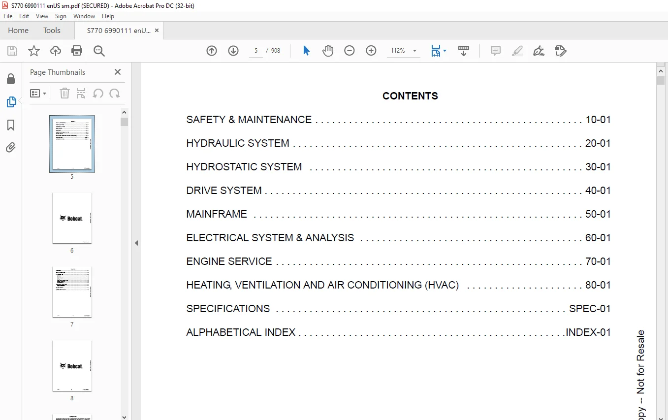
TABLE OF CONTENTS:
Bobcat S770 Skid-Steer Loader Service Manual SN ASRV11001 & Above – PDF DOWNLOAD
MAINTENANCE SAFETY 3
CONTENTS 5
FOREWORD 7
FOREWORD 9
SAFETY INSTRUCTIONS 12
FIRE PREVENTION 14
Maintenance 14
Operation 14
Electrical 14
Hydraulic System 14
Fueling 14
Starting 14
Spark Arrestor Exhaust System 14
Welding And Grinding 15
Fire Extinguishers 15
SERIAL NUMBER LOCATIONS 16
Loader Serial Number 16
Engine Serial Number 16
DELIVERY REPORT 17
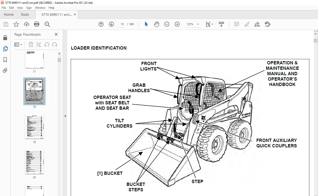
LOADER IDENTIFICATION 18
SAFETY & MAINTENANCE 19
LIFTING AND BLOCKING THE LOADER 23
Procedure 23
LIFT ARM SUPPORT DEVICE 25
Installing 25
Removing 26
OPERATOR CAB 27
Description 27
Raising 28
Lowering 29
Cab Door Sensor 30
Special Applications Kit 30
Special Applications Kit Inspection And Maintenance 30
Forestry Door And Window Kit 31
Forestry Door And Window Kit Inspection And Maintenance 31
TRANSPORTING LOADER ON A TRAILER 33
Loading And Unloading 33
Fastening 33
TOWING THE LOADER 35
Procedure 35
REMOTE START TOOL KIT-MEL1563 37
Remote Start Tool – MEL1563 37
Service Tool Harness Communicator – MEL1566 39
Remote Start Procedure 39
REMOTE START TOOL (SERVICE TOOL) KIT – 7003031 43
Description 43
Remote Start Tool (Service Tool) – 7003030 44
Loader Service Tool Harness – 6689747 45
Computer Service Tool Harness – 6689746 46
Remote Start Procedure 47
SERVICE SCHEDULE 51
Chart 51
AIR CLEANER SERVICE 53
Replacing Filter Elements 53
ENGINE COOLING SYSTEM 55
Maintenance Platform 55
Cleaning 55
Checking Level 57
Removing And Replacing Coolant 57
FUEL SYSTEM 59
Fuel Specifications 59
Biodiesel Blend Fuel 59
Filling The Fuel Tank 60
Fuel Filter 61
Removing Air From The Fuel System 61
ENGINE LUBRICATION SYSTEM 63
Checking And Adding Engine Oil 63
Engine Oil Chart 63
Removing And Replacing Oil And Filter 64
HYDRAULIC / HYDROSTATIC SYSTEM 65
Checking And Adding Fluid 65
Hydraulic / Hydrostatic Fluid Chart 65
Removing And Replacing Hydraulic Fluid 66
Removing And Replacing Hydraulic / Hydrostatic Filter 68
Removing And Replacing Hydraulic Charge Filter 69
Breather Cap 70
FINAL DRIVE TRANSMISSION (CHAINCASE) 71
Checking And Adding Oil 71
Removing And Replacing Oil 71
BOB-TACH (HAND LEVER) 73
Inspection And Maintenance 73
BOB-TACH (POWER) 75
Inspection And Maintenance 75
LUBRICATING THE LOADER 77
Lubrication Locations 77
TIRE MAINTENANCE 81
Wheel Nuts 81
Rotating 81
Mounting 81
SPARK ARRESTER MUFFLER 83
Cleaning Procedure 83
PIVOT PINS 85
Inspection And Maintenance 85
LOADER STORAGE AND RETURN TO SERVICE 87
Storage 87
Return To Service 87
STOPPING THE ENGINE AND LEAVING THE LOADER 89
Procedure 89
EMERGENCY EXIT 91
External Access 91
Rear Window 91
Front Door 91
SEAT BELT 93
Inspection And Maintenance 93
HYDRAULIC SYSTEM 95
HYDRAULIC / HYDROSTATIC SCHEMATICS 99
HYDRAULIC SYSTEM INFORMATION 107
Glossary Of Hydraulic / Hydrostatic Symbols 107
Troubleshooting 111
CYLINDER (LIFT) 113
Testing 113
Removal And Installation 114
Parts Identification 118
Disassembly 119
Assembly 120
CYLINDER (TILT) 123
Testing 123
Removal And Installation 124
Base End Pivot Pin Removal And Installation 126
Parts Identification 127
Disassembly 128
Assembly 130
CYLINDER (BOB-TACH) 133
Testing 133
Removal And Installation 134
Parts Identification 135
Disassembly 136
Assembly 137
MAIN RELIEF VALVE 141
Description 141
Testing 142
Adjusting 144
Removal And Installation 145
HYDRAULIC CONTROL VALVE (STANDARD) 147
Description 147
Removal And Installation 148
Mount Bracket Removal And Installation 151
Identification Chart 152
Lift Load Check Valve Removal And Installation 153
Load Check Valve Removal And Installation (Tilt And Auxiliary) 154
Anti-Cavitation Valve Removal And Installation (Lift, Rod End) 155
Port Relief / Anti-Cavitation Valve Removal And Installation (Lift, Base End) 155
Port Relief / Anti-Cavitation Valve Removal And Installation (Tilt, Base End) 156
Port Relief / Anti-Cavitation Valve Removal And Installation (Tilt, Rod End) 156
Port Relief Valve Removal And Installation 157
Plug Removal And Installation 158
Rubber Boot Removal And Installation 159
End Cap Block Removal And Installation 160
Lift Spool And Detent Removal And Installation 161
Tilt Spool Removal And Installation 171
Auxiliary Spool Removal And Installation 173
Auxiliary Solenoid Removal And Installation 175
Solenoid Removal And Installation 176
Lock Valve Removal And Installation 177
Lift Arm Bypass Orifice Removal And Installation 179
Main Relief Valve Removal And Installation 179
Check Valve Removal And Installation 180
HYDRAULIC CONTROL VALVE (ACS) OR (SJC) 181
Description 181
Removal And Installation 181
Actuator Removal And Installation (In Loader) 185
Actuator Removal And Installation (Out Of Loader) 187
Identification Chart 190
Mount Bracket Removal And Installation 191
Lift Load Check Valve Removal And Installation 191
Load Check Valve Removal And Installation (Tilt And Auxiliary) 192
Anti-Cavitation Valve Removal And Installation (Lift, Rod End) 193
Port Relief / Anti-Cavitation Valve Removal And Installation (Lift, Base End) 193
Port Relief / Anti-Cavitation Valve Removal And Installation (Tilt, Base End) 194
Port Relief / Anti-Cavitation Valve Removal And Installation (Tilt, Rod End) 194
Port Relief Valve Removal And Installation 195
Plug Removal And Installation 196
End Cap Block Removal And Installation 197
Lift Spool Removal And Installation 197
Lift Spool Disassembly And Assembly 199
Tilt Spool Removal And Installation 201
Auxiliary Spool Removal And Installation 203
Auxiliary Solenoid Removal And Installation 204
Solenoid Removal And Installation 205
Lock Valve Removal And Installation 206
Lift Arm Bypass Orifice Removal And Installation 207
Main Relief Valve Removal And Installation 207
Check Valve Removal And Installation 208
LIFT ARM BYPASS CONTROL VALVE 209
Description 209
Testing 209
Removal And Installation 210
Bracket Removal And Installation 211
Disassembly And Assembly 211
HYDRAULIC PUMP 213
Description 213
Pump Test At Quick Couplers 213
Direct Pump Test (Standard Section) 214
Direct Pump Test (Charge Section) 216
Removal And Installation 218
Hydraulic Pump Startup 220
Parts Identification 221
Disassembly And Assembly 222
HYDRAULIC PUMP (HIGH FLOW) 223
Description 223
Pump Test At Quick Couplers 223
Direct Pump Test (Standard Section) 224
Direct Pump Test (Charge Section) 225
Direct Pump Test (High Flow Section) 227
High Flow Relief Valve Adjustment 229
High Flow Relief Valve Removal And Installation 230
Solenoid Removal And Installation 231
Removal And Installation 232
Hydraulic Pump Startup 234
Parts Identification 235
Disassembly And Assembly 236
HYDRAULIC / HYDROSTATIC FILTERS 237
Description 237
Housing Removal And Installation 237
HYDRAULIC FLUID RESERVOIR 239
Description 239
Removal And Installation 239
Hydraulic Fluid Screen 240
OIL COOLER 241
Description 241
Removal And Installation 241
BUCKET POSITION VALVE 243
Description 243
Solenoid Removal And Installation 243
Solenoid Testing 244
Removal And Installation 244
Disassembly And Assembly 246
REAR AUXILIARY DIVERTER VALVE 247
Description 247
Solenoid Testing 247
Removal And Installation 248
Disassembly And Assembly 249
BOB-TACH (POWER) BLOCK 255
Description 255
Removal And Installation 255
Disassembly And Assembly 257
FRONT AUXILIARY HYDRAULIC COUPLER BLOCK 267
Description 267
Removal And Installation 267
Disassembly And Assembly 267
HYDROSTATIC SYSTEM 269
HYDROSTATIC SYSTEM INFORMATION 271
Troubleshooting 271
Description 272
HYDROSTATIC DRIVE MOTOR 273
Description 273
Removal And Installation 274
Parts Identification 276
Disassembly And Assembly 277
HYDROSTATIC DRIVE MOTOR (TWO-SPEED) 281
Description 281
Removal And Installation 281
Parts Identification 284
Disassembly 285
Assembly 291
HYDROSTATIC MOTOR CARRIER 297
Description 297
Removal And Installation 298
Parts Identification 299
Disassembly 300
Assembly 301
HYDROSTATIC MOTOR CARRIER (SJC) 303
Description 303
Removal And Installation 304
Parts Identification 305
Disassembly 306
Assembly 308
CHARGE PRESSURE 311
Description 311
Testing 311
Sender Removal And Installation 313
Adjusting 314
HYDROSTATIC PUMP 317
Description 317
Removal And Installation 318
Hydrostatic Pump Startup 319
Replenishing / High Pressure Relief Valve Removal And Installation 320
Parts Identification (Left Half) 321
Parts Identification (Right Half) 322
Disassembly 323
Assembly 330
HYDROSTATIC PUMP (SJC) 337
Description 337
Hydraulic Controller Removal And Installation 338
Removal And Installation 340
Hydrostatic Pump Start Up 342
Parts Identification 343
High Pressure Relief And Bypass Valve 344
Charge Relief Valve 345
Disassembly 346
Inspection 355
Assembly 359
Mechanical Neutral Adjustment 369
Hydraulic Controller Neutral Adjustment 372
DRIVE BELT 375
Belt Adjustment 375
Belt Replacement 375
Stop Adjustment 377
Tensioner Pulley Removal And Installation 378
Tensioner Pulley Disassembly And Assembly 378
TWO-SPEED / BRAKE VALVE 381
Description 381
Valve Block Removal And Installation 382
Valve Block Disassembly And Assembly 384
DRAIN MANIFOLD 387
Description 387
Drain Manifold Removal And Installation 387
DRIVE SYSTEM 389
BRAKE (SINGLE SPEED) 391
Description 391
Disc Removal And Installation 391
BRAKE (TWO-SPEED) 393
Description 393
DRIVE COMPONENTS 395
Description 395
Axle Seal Removal And Installation 396
Axle, Sprocket And Bearings Removal And Installation 398
Chain Removal And Installation 402
CHAINCASE 405
Description 405
Front Cover Removal And Installation 405
Center Cover Removal And Installation 406
Rear Cover Removal And Installation 407
MAINFRAME 409
SEAT BAR 413
Description 413
Removal And Installation 413
Disassembly And Assembly 414
Compression Spring Disassembly And Assembly 415
OPERATOR CAB 417
Gas Spring Removal And Installation 417
Gas Spring Bracket Disassembly And Assembly 418
Removal And Installation 418
OPERATOR SEAT 421
Removal And Installation 421
Seat Belt Removal And Installation (Retractable) 421
Seat Belt And Bracket Removal And Installation (Standard) 422
Seat Belt Bracket Removal And Installation 422
OPERATOR SEAT (SUSPENSION) 423
Removal And Installation 423
Slide Rail Removal And Installation 423
Seat Belt Removal And Installation 424
Lower Cushion Removal 424
Lower Cushion Installation 425
Back Cushion Removal And Installation 425
Shock Removal And Installation 426
3-Point Seat Belt Removal And Installation 426
BOB-TACH (HAND LEVER) 429
Description 429
Removal And Installation 429
Lever And Wedge Disassembly And Assembly 431
Pivot Pin Bushing And Seal Removal And Installation 433
BOB-TACH (POWER) 435
Description 435
Removal And Installation 435
Lever And Wedge Disassembly And Assembly 438
Pivot Pin Bushing And Seal Removal And Installation 439
LIFT ARMS 441
Stabilizer Bar Removal And Installation 441
Link Removal And Installation 442
Removal And Installation 443
REAR GRILLE 447
Removal And Installation 447
REAR DOOR (TAILGATE) 449
Removal And Installation 449
Striker Removal And Installation 450
Striker Disassembly And Assembly 450
Striker (Adjusting) 450
Latch Removal And Installation 451
FUEL TANK 453
Removal And Installation 453
Fuel Level Sender Removal And Installation 455
Fuel Fill Screen Removal And Installation 455
CONTROL PEDALS AND LINKAGES 457
Description 457
Pedal Removal And Installation 457
Linkage Removal And Installation 458
Pedal (Adjusting) 459
Floor Pan Removal And Installation 460
CONTROL PEDALS AND LINKAGES (ACS) 461
Description 461
Pedal Removal And Installation 461
Linkage Removal And Installation 462
Pedal (Adjusting) 462
Floor Pan Removal And Installation 463
CONTROL PANEL 465
Description 465
Removal And Installation 466
Disassembly And Assembly 467
Linkage Removal And Installation 469
Pintle Arm Disassembly And Assembly 473
Linkage Neutral (Adjusting) 474
Linkage Travel (Adjusting) 478
Shock Removal And Installation 482
CONTROL PANEL (SJC) 483
Description 483
Removal And Installation 483
CONTROL HANDLE / LEVER 485
Description 485
Lever Removal And Installation 485
Boot Removal And Installation 486
CONTROL HANDLE / LEVER (ACS) 487
Description 487
Handle Sensor Removal And Installation 487
Handle Removal And Installation 490
Handle Disassembly And Assembly 491
Lever Removal And Installation 491
Boot Removal And Installation 492
CONTROL HANDLE / LEVER (SJC) 493
Description 493
Joystick Testing 493
Joystick Removal And Installation 494
ACCESS PANEL (INSIDE) 495
Removal And Installation (Left) 495
Removal And Installation (Right) 495
ACCESS PANEL (INSIDE) (SJC) 497
Removal And Installation (Left) 497
Removal And Installation (Right) 497
WINDOW (REAR) 499
Removal And Installation 499
Disassembly And Assembly 499
WINDOW (TOP) 501
Removal And Installation 501
WINDOW (SIDE) 503
Removal And Installation 503
CAB DOOR 505
Description 505
Removal And Installation 505
Disassembly And Assembly 506
Aligning 507
Adjusting 508
Checking Operation 508
ARMREST 509
Description 509
Removal And Installation 510
Disassembly And Assembly 511
LEFT SIDE LOWER PANEL 513
Removal And Installation 513
Disassembly And Assembly 515
RIGHT SIDE LOWER PANEL 517
Removal And Installation 517
Disassembly And Assembly 518
HEADLINER 521
Removal And Installation 521
ELECTRICAL SYSTEM & ANALYSIS 523
ELECTRICAL SCHEMATICS 527
ELECTRICAL SYSTEM INFORMATION 559
Glossary Of Electrical Symbols 559
Standard Cab Harness Connectors 562
Deluxe Cab Harness Connectors 563
Mainframe Harness Connectors 564
Description 565
Troubleshooting 566
Fuse And Relay Location / Identification 567
Solenoid Testing 569
BATTERY 571
Removal And Installation 571
Servicing 572
Using A Booster Battery (Jump Starting) 573
ALTERNATOR 575
Belt Adjustment 575
Belt Replacement 575
Charging System Inspection 576
Alternator Voltage Testing 577
Low Voltage Testing 577
High Voltage Testing 578
Removal And Installation 579
Parts Identification 580
STARTER 581
Testing 581
Removal And Installation 581
Parts Identification 582
INSTRUMENT PANELS 583
Left Panel 583
Display Screen 585
Right Panel (Standard Key Panel) 586
Right Panel (Keyless Start Panel) 587
Right Panel (Deluxe Instrumentation Panel) 588
Left Switch Panel 590
Right Switch Panel 590
Left Panel Removal And Installation 591
Right Panel (Standard Key Panel) Removal And Installation 591
Right Panel (Keyless Start Panel) Removal And Installation 592
Right Panel (Deluxe Instrumentation Panel) Removal And Installation 592
Key Switch Disassembly And Assembly 593
Alarm Disassembly And Assembly 593
Left Switch Panel Removal And Installation 594
Right Switch Panel Removal And Installation 594
LIGHTS 595
Front Removal And Installation 595
Rear Removal And Installation 596
Cab Light Removal And Installation 596
BOBCAT CONTROLLERS (GATEWAY AND AUXILIARY) 597
Description 597
Connector Identification 598
Removal And Installation 604
BOBCAT CONTROLLER (ACS) 605
Description 605
Connector And Wire Identification 606
Removal And Installation 607
BOBCAT CONTROLLER (SJC) (DRIVE) 609
Description 609
Connector Identification 610
Removal And Installation 612
SPEED SENSORS (SJC) 613
Description 613
Testing 613
Removal And Installation 615
DIAGNOSTIC SERVICE CODES 617
Viewing Service Codes 617
Service Codes List 618
BOBCAT INTERLOCK CONTROL SYSTEM (BICS™) 623
Description 623
Inspecting The BICS™ (Engine STOPPED – Key ON) 624
Inspecting Deactivation Of The Auxiliary Hydraulics System (Engine STOPPED – Key ON) 624
Inspecting The Seat Bar Sensor (Engine RUNNING) 624
Inspecting The Traction Lock (Engine RUNNING) 624
Inspecting The Lift Arm Bypass Control 624
Inspecting Deactivation Of Lift And Tilt Functions (ACS And SJC) 624
Troubleshooting 625
SEAT BAR SENSOR 627
Description 627
Troubleshooting 627
Testing 628
Removal And Installation 629
Bobcat Interlock Control System (BICS™) Circuit Test 632
TRACTION LOCK 635
Description 635
Troubleshooting 636
Inspecting 637
CONTROL SYSTEM (ACS) 639
Description 639
Troubleshooting 640
Handle Sensor Connector Disassembly And Assembly 641
Switch Handle Removal 642
Switch Handle Installation 644
Actuator Connector Disassembly And Assembly 647
Handle Lock Solenoid Removal And Installation 648
Handle Lock Solenoid Disassembly And Assembly 648
Foot Sensor Removal And Installation 649
Foot Sensor Disassembly And Assembly 650
Foot Sensor Lock Solenoid Removal And Installation 650
ELECTRICAL / HYDRAULIC CONTROLS 651
Identification Chart 651
Description 652
Identification Chart ACD Group 0 653
Identification Chart ACD Group 1 654
Identification Chart ACD Group 2 655
Identification Chart ACD Group 3 656
ELECTRICAL / HYDRAULIC CONTROLS (ACS) 657
Identification Chart 657
Description 658
Identification Chart ACD Group 0 659
Identification Chart ACD Group 1 660
Identification Chart ACD Group 2 661
Identification Chart ACD Group 3 662
ELECTRICAL / HYDRAULIC CONTROLS (SJC) 663
Identification Chart 663
Description 664
Identification Chart ACD Group 0 665
Identification Chart ACD Group 1 666
Identification Chart ACD Group 2 667
Identification Chart ACD Group 3 668
SERVICE PC (LAPTOP COMPUTER) 669
Connecting Remote Start Tool 669
Connecting Remote Start Tool (Service Tool) 669
CALIBRATION 671
Description 671
Actuator Testing 671
Lift And Tilt Calibration (SJC) 674
Hydrostatic Pump Calibration (SJC) 676
Lift And Tilt Calibration (ACS) 681
STEERING DRIFT COMPENSATION 683
Description 683
Operation 683
FLYWHEEL RPM SENSOR 685
Description 685
Adjustment 686
CONTROL PANEL SETUP 687
Right Panel Setup (Deluxe Instrumentation Panel) 687
PASSWORD SETUP (DELUXE INSTRUMENTATION PANEL) 689
Password Description 689
Changing The Owner Password 689
Changing The User Passwords 690
Password Lockout Feature 690
PASSWORD SETUP (KEYLESS START PANEL) 691
Password Description 691
Changing The Owner Password 691
Password Lockout Feature 691
MAINTENANCE CLOCK 693
Description 693
Setup 694
Reset 697
BACK-UP ALARM SYSTEM 699
Description 699
Inspecting 699
Adjusting Switch Position 700
Troubleshooting (Standard And ACS) 701
Troubleshooting (Joystick) 702
Alarm Removal And Installation 703
Switch Removal And Installation 703
FRONT HORN 705
Removal And Installation 705
ENGINE SERVICE 707
ENGINE INFORMATION 711
Description 711
Specifications 712
Torque Values 715
Troubleshooting 715
Engine Removal And Installation 717
Engine Mount Replacement 724
Compression – Checking 725
ENGINE SPEED CONTROL (SCPA) 727
Removal And Installation 727
Disassembly And Assembly 727
Cable Removal And Installation 728
ENGINE SPEED CONTROL (SJC) 729
Removal And Installation 729
Disassembly And Assembly 730
MUFFLER 733
Removal And Installation 733
AIR CLEANER 735
Housing Removal And Installation 735
ENGINE COOLING SYSTEM 737
Radiator Removal And Installation 737
Hydraulic Fan Description 740
Hydraulic Fan Disassembly And Assembly 741
Lower Fan Duct Removal And Installation 742
Blower Housing Removal And Installation 742
Hydraulic Fan Motor Assembly Removal And Installation 743
Fan Removal And Installation 743
Hydraulic Fan Motor Removal And Installation 744
Water Pump Removal And Installation 745
Water Pump Disassembly And Assembly 745
Thermostat Housing Removal And Installation 746
Thermostat – Checking 746
LUBRICATION SYSTEM 747
Oil Pan Removal And Installation 747
Oil Pump Removal And Installation 748
Oil Pump Inspection 748
Oil Filter Cooler Removal And Installation 750
Engine Oil Pressure – Testing 751
FUEL SYSTEM 753
Fuel Shutoff Solenoid – Checking 753
Fuel Shutoff Solenoid Removal And Installation 753
Fuel Injection Pump Assembly Removal 754
Fuel Injection Pump Assembly Installation 757
Governor Housing Disassembly And Assembly 760
Governor Disassembly And Assembly 761
Fuel Camshaft Removal And Installation 763
Fuel Injection Pump Removal 765
Injection Pump – Timing 771
Fuel Injector Removal And Installation 774
Fuel Injector Nozzle Pressure – Checking 775
Nozzle Spraying Condition 776
Valve Seat Tightness 776
CYLINDER HEAD 777
Intake Air Heater – Testing 777
Intake Air Heater Removal And Installation 777
Valve Clearance Adjustment 778
Valve Timing – Checking 780
Cylinder Head Removal And Installation 781
Cylinder Head Disassembly And Assembly 783
Cylinder Head – Servicing 784
Cylinder Head Top Clearance 785
Valve Guide – Checking 786
Reconditioning The Valve And Valve Seat 788
Valve Spring 790
Valve Tappets 791
Rocker Arm And Shaft – Checking 792
Push Rod Alignment – Checking 792
CRANKSHAFT AND PISTONS 793
Piston And Connecting Rod Removal And Installation 793
Piston And Connecting Rod – Servicing 795
Cylinder Bore – Checking 799
Connecting Rod Alignment 800
Crankshaft Gear Removal And Installation 800
Crankshaft And Bearings Removal 801
Crankshaft And Bearings Installation 803
Crankshaft And Bearings – Servicing 805
CAMSHAFT AND TIMING GEArS 811
Timing Gearcase Cover Removal And Installation 811
Timing Gears Backlash – Checking 812
Idler Gear And Camshaft Removal And Installation 812
Camshaft – Servicing 813
Idler Gear And Shaft – Servicing 815
TURBOCHARGER 817
Description 817
Testing 817
Removal And Installation 819
FLYWHEEL AND HOUSING 821
Flywheel Removal And Installation 821
Ring Gear Removal And Installation 821
Housing Removal And Installation 822
EXHAUST GAS RECIRCULATION (EGR) SYSTEM 823
Description 823
Testing 824
Removal And Installation 827
HEATING, VENTILATION AND AIR CONDITIONING (HVAC) 829
AIR CONDITIONING SYSTEM FLOW 831
Description 831
Chart 832
Components 833
Safety Equipment 836
REGULAR MAINTENANCE 837
Filters 837
Compressor Drive Belt Adjustment 838
Compressor Drive Belt Replacement 838
Condenser 838
Air Conditioning Lubrication 838
Air Conditioning Service Chart 839
Evaporator / Heater Coil 840
TROUBLESHOOTING 841
Blower Motor Does Not Operate 841
Blower Motor Operates Normally, But Air Flow Is Insufficient 841
Insufficient Cooling Although Air Flow And Compressor Operation Are Normal 841
The Compressor Does Not Operate At All, Or Operates Improperly 841
Gauge Pressure Related Troubleshooting 842
Troubleshooting Tree 844
Temperature / Pressure Chart 847
Poor A/C Performance 849
HVAC Repair And Leaks 850
Electrical System 851
Engine Coolant Bypassing The Heater Valve 857
Heater Valve Not Opening Or Closing 858
SYSTEM CHARGING AND RECLAMATION 859
Refrigerant Identification 859
Reclamation And Charging With Recovery / Charging Unit 860
COMPRESSOR 863
Removal And Installation 863
Oil 865
Oil Check 866
CONDENSER 867
Removal And Installation 867
RECEIVER / DRIER 869
Receiver / Drier Removal And Installation 869
Pressure Relief Valve Removal And Installation 870
Pressure Switch Removal And Installation 871
Schrader® Valve Removal And Installation 872
EVAPORATOR / HEATER UNIT 873
Removal And Installation 873
THERMOSTAT 875
Description 875
Removal And Installation 876
EXPANSION VALVE 877
Removal And Installation 877
EVAPORATOR COIL 879
Removal And Installation 879
HEATER COIL 881
Removal And Installation 881
BLOWER FAN 883
Removal And Installation 883
Disassembly And Assembly 883
HEATER VALVE 887
Removal And Installation 887
SPECIFICATIONS 889
(S770) LOADER SPECIFICATIONS 891
Machine Dimensions 891
Performance 892
Engine 892
Drive System 893
Controls 893
Hydraulic System 894
Electrical System 895
Capacities 895
Tires 895
TORQUE SPECIFICATIONS FOR BOLTS 897
Torque For General SAE Bolts 897
Torque For General Metric Bolts 898
HYDRAULIC CONNECTION SPECIFICATIONS 899
Straight Thread O-ring Fitting 899
Flare Fitting 900
Tubelines And Hoses 900
HYDRAULIC / HYDROSTATIC FLUID SPECIFICATIONS 901
Specifications 901
CONVERSIONS 903
Decimal And Millimeter Equivalent Chart 903
U S To Metric Conversion Chart 903
ALPHABETICAL INDEX 905
Questions? Email us: [email protected]
PLEASE NOTE:
- This is the SAME exact manual used by your dealers to fix your vehicle.
- The same can be yours in the next 2-3 mins as you will be directed to the download page immediately after paying for the manual.
- Any queries / doubts regarding your purchase, please feel free to contact [email protected]
S.V