Bobcat S850 Skid-Steer Loader Service Manual 6990257 – PDF DOWNLOAD
$36.95
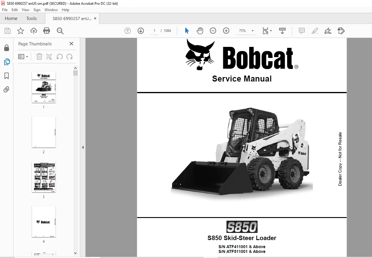
Bobcat S850 Skid-Steer Loader Service Manual 6990257 – PDF DOWNLOAD
S/N ATF411001 & Above
S/N ATF511001 & Above
Description
Bobcat S850 Skid-Steer Loader Service Manual 6990257 – PDF DOWNLOAD
FILE DETAILS:
Bobcat S850 Skid-Steer Loader Service Manual 6990257 – PDF DOWNLOAD
Language : English
Pages : 1084
Downloadable : Yes
File Type : PDF
IMAGES PREVIEW OF THE MANUAL:
DESCRIPTION:
Bobcat S850 Skid-Steer Loader Service Manual 6990257 – PDF DOWNLOAD
S/N ATF411001 & Above
S/N ATF511001 & Above
FOREWORD:
This manual is for the Bobcat loader mechanic. It provides necessary servicing and adjustment procedures for the Bobcat loader and its component parts and systems. Refer to the Operation & Maintenance Manual for operating instructions, starting procedure, daily checks, etc.
A general inspection of the following items must be made after the loader has had service or repair:
TABLE OF CONTENTS:
Bobcat S850 Skid-Steer Loader Service Manual 6990257 – PDF DOWNLOAD
MAINTENANCE SAFETY 3
CONTENTS 5
FOREWORD 7
FOREWORD 9
SAFETY INSTRUCTIONS 11
FIRE PREVENTION 13
Maintenance 13
Operation 13
Electrical 13
Hydraulic System 13
Fueling 13
Starting 13
Spark Arrester Exhaust System 13
Welding And Grinding 14
Fire Extinguishers 14
SERIAL NUMBER LOCATIONS 15
Loader Serial Number 15
Engine Serial Number 15
DELIVERY REPORT 16
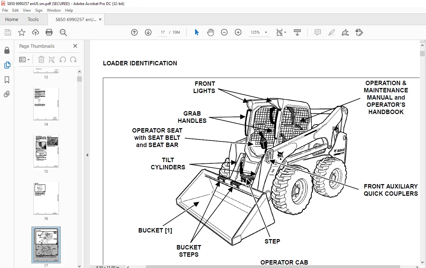
LOADER IDENTIFICATION 17
SAFETY & MAINTENANCE 19
LIFTING AND BLOCKING THE LOADER 23
Procedure 23
LIFT ARM SUPPORT DEVICE 25
Description 25
Installing 25
Removing 26
OPERATOR CAB 27
Description 27
Raising 27
Lowering 28
Cab Door Sensor 29
Special Applications Kit 30
Special Applications Kit Inspection And Maintenance 30
Forestry Door And Window Kit 31
Forestry Door And Window Kit Inspection And Maintenance 31
TRANSPORTING THE LOADER ON A TRAILER 33
Loading And Unloading 33
Fastening 33
TOWING THE LOADER 35
Procedure 35
REMOTE START TOOL KIT – MEL1563 37
Remote Start Tool – MEL1563 37
Service Tool Harness Communicator – MEL1566 39
Remote Start Procedure 39
REMOTE START TOOL (SERVICE TOOL) KIT – 7217666 43
Description 43
Remote Start Tool (Service Tool) – 7022042 44
Loader Service Tool Harness – 6689747 45
Computer Service Tool Harness – 6689746 46
Remote Start Procedure 47
DIAGMASTER (SERVICE TOOL) KIT – 7024161 51
Diagmaster (Service Tool) 51
DST-i LED Table 52
DST-i Operation Status And Display Specification 52
Diagmaster (Service Tool) Procedure 53
SERVICE SCHEDULE 57
Maintenance Intervals 57
ENGINE AIR CLEANER 59
Replacing Filter Elements 59
ENGINE COOLING SYSTEM 61
Maintenance Platform 61
Cleaning 61
Checking And Adding Coolant 63
Removing And Replacing Coolant 64
FUEL SYSTEM 65
Fuel Specifications 65
Biodiesel Blend Fuel 65
Filling The Fuel Tank 66
Fuel Filter 67
Removing Air From The Fuel System 68
ENGINE LUBRICATION SYSTEM 69
Checking And Adding Engine Oil 69
Engine Oil Chart 69
Removing And Replacing Oil And Filter 70
HYDRAULIC / HYDROSTATIC SYSTEM 73
Checking And Adding Fluid 73
Hydraulic / Hydrostatic Fluid Chart 73
Removing And Replacing Hydraulic Fluid 74
Removing And Replacing Hydraulic / Hydrostatic Filter 76
Removing And Replacing Hydraulic Charge Filter 77
Replacing Reservoir Breather Cap 79
FINAL DRIVE TRANSMISSION (CHAINCASE) 81
Checking And Adding Fluid 81
Removing And Replacing Fluid 81
BOB-TACH (HAND LEVER) 83
Inspection And Maintenance 83
BOB-TACH (POWER) 85
Inspection And Maintenance 85
LUBRICATING THE LOADER 87
Lubrication Locations 87
TIRE MAINTENANCE 91
Wheel Nuts 91
Rotating 91
Mounting 92
PIVOT PINS 93
Inspection And Maintenance 93
LOADER STORAGE AND RETURN TO SERVICE 95
Storage 95
Return To Service 95
STOPPING THE ENGINE AND LEAVING THE LOADER 97
Procedure 97
EMERGENCY EXIT 99
Rear Window Identification 99
Rear Window Removal (Latches) 99
Rear Window Removal (Rubber Cord) 100
External Access (Rear Window With Latches) 100
External Access (Rear Window With Rubber Cord) 101
Front Door 101
SEAT BELT 103
Inspection And Maintenance 103
HYDRAULIC SYSTEM 105
HYDRAULIC / HYDROSTATIC SCHEMATICS 111
HYDRAULIC SYSTEM INFORMATION 121
Glossary Of Hydraulic / Hydrostatic Symbols 121
Troubleshooting 125
CYLINDER (LIFT) 127
Testing 127
Removal And Installation 128
Parts Identification (Earlier Models) 132
Parts Identification (Later Models) 133
Disassembly 134
Assembly 136
CYLINDER (TILT) 139
Testing 139
Removal And Installation 140
Base End Pivot Pin Removal And Installation 142
Parts Identification (Earlier Models) 143
Parts Identification (Later Models) 144
Disassembly 145
Assembly 148
CYLINDER (BOB-TACH) 153
Testing 153
Removal And Installation 154
Parts Identification 155
Disassembly 156
Assembly 158
MAIN RELIEF VALVES 161
Description 161
Testing 161
Main Relief Valve Adjustment 164
Main Relief Valve Removal And Installation 164
Auxiliary Relief Valve Adjustment 165
Auxiliary Relief Valve Removal And Installation 166
HYDRAULIC CONTROL VALVE (SJC) 167
Description 167
Removal And Installation 167
Actuator Removal And Installation (In Loader) 172
Actuator Removal And Installation (Out Of Loader) 173
Identification Chart 176
Mount Bracket Removal And Installation 177
Lift Load Check Valve Removal And Installation 177
Load Check Valve Removal And Installation (Tilt And Auxiliary) 178
Anti-Cavitation Valve Removal And Installation (Lift, Rod End) 179
Port Relief / Anti-Cavitation Valve Removal And Installation (Lift, Base End) 179
Port Relief / Anti-Cavitation Valve Removal And Installation (Tilt, Base End) 180
Port Relief / Anti-Cavitation Valve Removal And Installation (Tilt, Rod End) 180
Port Relief Valve Removal And Installation 181
Plug Removal And Installation 183
End Cap Block Removal And Installation 184
Lift Spool Removal And Installation 184
Lift Spool Disassembly And Assembly 186
Tilt Spool Removal And Installation 187
Auxiliary Spool Removal And Installation 189
Auxiliary Solenoid Removal And Installation 190
Solenoid Removal And Installation 191
Lock Valve Removal And Installation 192
Lift Arm Bypass Orifice Removal And Installation 194
Main Relief Valve Removal And Installation 194
Auxiliary Relief Valve Removal And Installation 195
Check Valve Removal And Installation 195
HYDRAULIC CONTROL VALVE (SCPA) 197
Description 197
Removal And Installation 198
Mount Bracket Removal And Installation 202
Identification Chart 203
Lift Load Check Valve Removal And Installation 204
Load Check Valve Removal And Installation (Tilt And Auxiliary) 205
Anti-Cavitation Valve Removal And Installation (Lift, Rod End) 206
Port Relief / Anti-Cavitation Valve Removal And Installation (Lift, Base End) 206
Port Relief / Anti-Cavitation Valve Removal And Installation (Tilt, Base End) 207
Port Relief / Anti-Cavitation Valve Removal And Installation (Tilt, Rod End) 207
Port Relief Valve Removal And Installation 208
Plug Removal And Installation 210
Rubber Boot Removal And Installation 211
End Cap Block Removal And Installation 211
Lift Spool And Detent Removal And Installation 212
Tilt Spool Removal And Installation 220
Auxiliary Spool Removal And Installation 222
Auxiliary Solenoid Removal And Installation 223
Solenoid Removal And Installation 223
Lock Valve Removal And Installation 225
Lift Arm Bypass Orifice Removal And Installation 227
Main Relief Valve Removal And Installation 227
Auxiliary Relief Valve Removal And Installation 228
Check Valve Removal And Installation 228
LIFT ARM BYPASS CONTROL VALVE 231
Description 231
Testing 231
Removal And Installation 232
Bracket Removal And Installation 233
Disassembly And Assembly 233
HYDRAULIC PUMP 235
Description 235
Pump Test At Quick Couplers 236
Direct Pump Test (Standard Section) 237
Direct Pump Test (Charge Section) 239
Removal And Installation 241
Hydraulic Pump Startup 243
Parts Identification 244
Disassembly And Assembly 245
HYDRAULIC PUMP (HIGH FLOW) 247
Description 247
Pump Test At Quick Couplers 248
Direct Pump Test (Standard Section) 249
Direct Pump Test (Charge Section) 250
Direct Pump Test (High Flow Section) 252
High Flow Relief Valve Adjustment 254
High Flow Relief Valve Removal And Installation 255
Solenoid Removal And Installation 256
Removal And Installation 257
Hydraulic Pump Startup 259
Parts Identification 260
Disassembly And Assembly 261
HYDRAULIC / HYDROSTATIC FILTERS 263
Description 263
Housing Removal And Installation 264
HYDRAULIC FLUID RESERVOIR 265
Description 265
Removal And Installation 265
Hydraulic Fluid Screen 266
OIL COOLER 267
Description 267
Removal And Installation 268
BUCKET POSITION VALVE 269
Description 269
Solenoid Removal And Installation 269
Solenoid Testing 271
Removal And Installation 271
Disassembly And Assembly 274
REAR AUXILIARY DIVERTER VALVE 275
Description 275
Solenoid Testing 275
Removal And Installation 276
Disassembly And Assembly 277
BOB-TACH (POWER) BLOCK (EARLIER MODELS) 283
Description 283
Removal And Installation 283
Disassembly And Assembly 285
BOB-TACH (POWER) BLOCK (LATER MODELS) 293
Description 293
Testing Relief Valve 294
Removal And Installation 296
Disassembly And Assembly 298
FRONT AUXILIARY HYDRAULIC COUPLER BLOCK 303
Description 303
Removal And Installation 304
Disassembly And Assembly (FFI/FI) 304
Disassembly And Assembly (FFH/FH) 306
HYDROSTATIC SYSTEM 309
HYDROSTATIC SYSTEM INFORMATION 311
Description 311
Troubleshooting 312
HYDROSTATIC MOTOR (TWO-SPEED) (S/N ATF411001 – ATF411599) 313
Description 313
Removal And Installation 313
Parts Identification 316
Disassembly 317
Assembly 323
HYDROSTATIC MOTOR (TWO-SPEED) (S/N ATF411600 & ABOVE AND S/N ATF511001 & ABOVE) 329
Description 329
Removal And Installation 329
Parts Identification 332
Disassembly 333
Assembly 339
HYDROSTATIC MOTOR CARRIER (SJC AND SCPA) 345
Description 345
Removal And Installation 346
Parts Identification 348
Disassembly 349
Assembly 351
CHARGE PRESSURE 353
Description 353
Testing 353
Sender Removal And Installation 355
Adjusting 356
HYDROSTATIC PUMP (SJC AND SCPA) 357
Description 357
Hydraulic Controller Removal And Installation 358
Removal And Installation 360
Hydrostatic Pump Startup 361
Parts Identification 362
High Pressure Relief And Bypass Valve 363
Charge Relief Valve 364
Disassembly 365
Inspection 374
Assembly 377
Mechanical Neutral Adjustment 385
Hydraulic Controller Neutral Adjustment 388
DRIVE BELT 391
Belt Adjustment 391
Stop Adjustment 391
Belt Replacement 391
Tensioner Pulley Removal And Installation 394
Tensioner Pulley Disassembly And Assembly 394
TWO-SPEED / BRAKE VALVE (S/N ATF411001 – ATF411599) 397
Description 397
Valve Block Removal And Installation 398
Valve Block Disassembly And Assembly 400
TWO-SPEED / BRAKE VALVE (S/N ATF411600 & ABOVE AND S/N ATF511001 & ABOVE) 403
Description 403
Valve Block Removal And Installation 404
Valve Block Disassembly And Assembly 406
DRAIN MANIFOLD 409
Description 409
Drain Manifold Removal And Installation 409
DRIVE SYSTEM 411
BRAKE (TWO-SPEED) 413
Description 413
DRIVE COMPONENTS 415
Description 415
Axle Seal Removal And Installation 416
Axle, Sprocket And Bearings Removal And Installation 418
Chain Removal And Installation 422
CHAINCASE 425
Description 425
Front Cover Removal And Installation 425
Center Cover Removal And Installation 426
Rear Cover Removal And Installation 427
MAINFRAME 429
SEAT BAR 433
Description 433
Removal And Installation 433
Disassembly And Assembly 434
Compression Spring Disassembly And Assembly 435
OPERATOR CAB 437
Gas Spring Removal And Installation 437
Gas Spring Bracket Disassembly And Assembly 438
Removal And Installation 439
OPERATOR SEAT (SUSPENSION) 441
Removal And Installation 441
Slide Rail Removal And Installation 441
Seat Belt Removal And Installation 442
Lower Cushion Removal 442
Lower Cushion Installation 443
Back Cushion Removal And Installation 443
Shock Removal And Installation 444
3-Point Seat Belt Removal And Installation 444
BOB-TACH (HAND LEVER) 447
Description 447
Removal And Installation 447
Lever And Wedge Disassembly And Assembly 449
Pivot Pin Bushing And Seal Removal And Installation 451
BOB-TACH (POWER) 453
Description 453
Removal And Installation 453
Lever And Wedge Disassembly And Assembly 456
Pivot Pin Bushing And Seal Removal And Installation 458
LIFT ARMS 459
Stabilizer Bar Removal And Installation 459
Link Removal And Installation 460
Removal And Installation 462
REAR GRILLE 467
Removing 467
Installing 467
Shield Removal And Installation 468
REAR DOOR (TAILGATE) 469
Removal And Installation 469
Striker Removal And Installation 470
Striker Disassembly And Assembly 470
Striker (Adjusting) 470
Latch Removal And Installation (Earlier Models) 471
Latch Removal And Installation (Later Models) 472
FUEL TANK 473
Removal And Installation 473
Fuel Level Sender Removal And Installation 474
Fuel Fill Screen Removal And Installation 475
FUEL TANK (AUXILIARY) 477
Removal And Installation 477
CONTROL PEDALS AND LINKAGES (SCPA) 479
Description 479
Pedal Removal And Installation 479
Linkage Removal And Installation 480
Pedal (Adjusting) 481
Floor Pan Removal And Installation 482
CONTROL PANEL (SJC) 483
Description 483
Removal And Installation 483
CONTROL PANEL (SCPA) 485
Description 485
Removal And Installation 485
CONTROL HANDLE / LEVER (SJC) 487
Description 487
Joystick Testing 487
Joystick Removal And Installation 488
CONTROL HANDLE / LEVER (SCPA) 489
Description 489
Steering Handle Testing 489
Steering Handle Removal And Installation 490
ACCESS PANEL (INSIDE) (SJC) 491
Removal And Installation (Left) 491
Removal And Installation (Right) 492
ACCESS PANEL (INSIDE) (SCPA) 493
Removal And Installation (Left) 493
Removal And Installation (Right) 493
WINDOW (REAR) 495
Rear Window Identification 495
Removal (Rubber Cord) 495
Installation (Rubber Cord) 496
Removal And Installation (Latches) 498
Disassembly And Assembly (Latches) 498
WINDOW (TOP) 499
Removal And Installation 499
WINDOW (SIDE) 501
Removal And Installation 501
CAB DOOR 503
Description 503
Removal And Installation 503
Disassembly And Assembly 504
Aligning 505
Adjusting 506
Checking Operation 506
ARMREST 507
Description 507
Removal And Installation 508
Disassembly And Assembly 509
LEFT SIDE LOWER PANEL 511
Removal And Installation 511
Disassembly And Assembly 514
RIGHT SIDE LOWER PANEL 515
Removal And Installation 515
Disassembly And Assembly 517
HEADLINER 519
Removal And Installation 519
ELECTRICAL SYSTEM AND ANALYSIS 521
ELECTRICAL SCHEMATICS 525
ELECTRICAL SYSTEM INFORMATION 675
Glossary Of Electrical Symbols 675
Deluxe Cab Harness Connectors (Earlier Models) 678
Deluxe Cab Harness Connectors (Later Models) 679
Mainframe Harness Connectors 680
Engine Harness Connectors 681
Description 682
Troubleshooting 683
Fuse And Relay Location / Identification 684
Solenoid Testing 687
BATTERY 689
Removal And Installation 689
Servicing 690
Using A Booster Battery (Jump Starting) 691
ALTERNATOR 693
Belt Adjustment 693
Belt Replacement 693
Charging System Inspection 694
Alternator Voltage Testing 695
Low Voltage Testing 695
High Voltage Testing 696
Removal And Installation 697
Parts Identification 699
STARTER 701
Testing 701
Removal And Installation 701
Parts Identification 702
INSTRUMENT PANELS 703
Left Panel 703
Display Screen 705
Right Panel (Standard Key Panel) 705
Right Panel (Keyless Start Panel) 706
Right Panel (Deluxe Instrumentation Panel) 707
Left Switch Panel 709
Right Switch Panel 709
Left Side Lower Panel 710
Right Side Lower Panel 710
Left Panel Removal And Installation 711
Right Panel Removal And Installation 711
Key Switch Disassembly And Assembly 712
Alarm Disassembly And Assembly 712
Left Switch Panel Removal And Installation 713
Right Switch Panel Removal And Installation 713
LIGHTS 715
Front Removal And Installation 715
Rear Removal And Installation 716
Cab Light Removal And Installation (Earlier Models) 716
Cab Light Removal And Installation (Later Models) 717
BOBCAT CONTROLLERS (GATEWAY AND AUXILIARY) 719
Description 719
Connector Identification 720
Removal And Installation 726
BOBCAT CONTROLLER (ACS) 727
Description 727
Connector And Wire Identification 728
Removal And Installation 729
BOBCAT CONTROLLER (SJC) (DRIVE) 731
Description 731
Connector Identification 732
Removal And Installation 734
BOBCAT CONTROLLER (SCPA) (DRIVE) 735
Description 735
Connector Identification 736
Removal And Installation 738
ENGINE CONTROL UNIT (ECU) 739
Description 739
Cleaning 740
Removal And Installation 741
ECU Replacement 742
DIAGNOSTIC SERVICE CODES 743
Viewing Service Codes 743
Service Codes List 744
DIAGMASTER DIAGNOSTIC TROUBLE CODES (DTC) 751
Viewing Trouble Codes 751
BOBCAT INTERLOCK CONTROL SYSTEM (BICS™) 753
Description 753
Inspecting The BICS™ (Engine STOPPED – Key ON) 754
Inspecting Deactivation Of The Auxiliary Hydraulics System (Engine STOPPED – Key ON) 754
Inspecting The Seat Bar Sensor (Engine RUNNING) 754
Inspecting The Traction Lock (Engine RUNNING) 754
Inspecting The Lift Arm Bypass Control 754
Inspecting Deactivation Of Lift And Tilt Functions (SJC) 754
Troubleshooting 755
SEAT BAR SENSOR 757
Description 757
Troubleshooting 757
Testing 758
Removal And Installation 759
Bobcat Interlock Control System (BICS™) Circuit Test 762
TRACTION LOCK 765
Description 765
Troubleshooting 766
Inspecting 767
ELECTRICAL / HYDRAULIC CONTROLS (SJC) 769
Identification Chart 769
Description 770
Identification Chart ACD Group 0 771
Identification Chart ACD Group 1 772
Identification Chart ACD Group 2 773
Identification Chart ACD Group 3 774
ELECTRICAL / HYDRAULIC CONTROLS (SCPA) 775
Identification Chart 775
Description 776
Identification Chart ACD Group 0 777
Identification Chart ACD Group 1 778
Identification Chart ACD Group 2 779
Identification Chart ACD Group 3 780
SERVICE PC (LAPTOP COMPUTER) 781
Connecting Remote Start Tool 781
Connecting Remote Start Tool (Service Tool) 781
Connecting Diagmaster (Service Tool) 782
Connecting Remote Parked Regeneration Kit 782
CALIBRATION 783
Description 783
Actuator Testing 783
Lift And Tilt Calibration (SJC) 786
Hydrostatic Pump Calibration (SJC) 788
Hydrostatic Pump Calibration (SCPA) 793
STEERING DRIFT COMPENSATION (OPERATOR MODE) 799
Description 799
Operation 799
STEERING DRIFT COMPENSATION (SERVICE MODE) 801
Description 801
Operation 801
CONTROL PANEL SETUP 803
Right Panel Setup (Deluxe Instrumentation Panel) 803
PASSWORD SETUP (DELUXE INSTRUMENTATION PANEL) 807
Password Description 807
Changing The Owner Password 807
Changing The User Passwords 808
Password Lockout Feature 808
PASSWORD SETUP (KEYLESS START PANEL) 809
Password Description 809
Changing The Owner Password 809
Password Lockout Feature 809
MAINTENANCE CLOCK 811
Description 811
Setup 812
Reset 815
BACK-UP ALARM SYSTEM 817
Description 817
Inspecting 817
Troubleshooting (Joystick) 818
Alarm Removal And Installation 819
FRONT HORN 821
Removal And Installation 821
Troubleshooting 822
Troubleshooting (Joystick) 823
ENGINE SERVICE 825
ENGINE INFORMATION 829
Description 829
Specifications 830
Sensor Location 833
Torque Values 836
Troubleshooting 837
Engine Removal And Installation 838
Engine Mount Replacement 850
Compression – Testing 852
Injector Signal – Testing 855
ENGINE SPEED CONTROL (HAND) 857
Removal And Installation 857
ENGINE SPEED CONTROL (FOOT) 859
Removal And Installation 859
Disassembly And Assembly 860
Foot Throttle Calibration 862
DIESEL PARTICULATE FILTER (DPF) SYSTEM 865
Description 865
Removal And Installation 866
DPF Regeneration 869
DPF Regeneration Table 869
Operation (Standard Switch) 870
Operation (Optional Inhibit Switch Kit) 871
Operation (Optional Remote Parked Regeneration Kit) 872
Remote Parked Regeneration (Level 3) 872
DPF Service Regeneration (Level 4) 874
DPF Cleaning (Level 5) 877
AIR CLEANER 879
Housing Removal And Installation 879
ENGINE COOLING SYSTEM 881
Radiator Removal And Installation 881
Hydraulic Fan Description 883
Lower Fan Duct Removal And Installation 884
Hydraulic Fan Motor Assembly Removal And Installation (Earlier Models) 884
Fan Removal And Installation (Earlier Models) 885
Hydraulic Fan Motor Removal And Installation (Earlier Models) 885
Hydraulic Fan Disassembly And Assembly (Earlier Models) 886
Hydraulic Fan Motor Assembly Removal And Installation (Later Models) 888
Fan Removal And Installation (Later Models) 889
Hydraulic Fan Motor Removal And Installation (Later Models) 890
Hydraulic Fan Disassembly And Assembly (Later Models) 891
Blower Housing Removal And Installation 896
Water Pump Removal And Installation 897
Water Pump Disassembly And Assembly 897
Thermostat Housing Removal And Installation 898
Thermostat – Checking 898
LUBRICATION SYSTEM 899
Oil Pan Removal And Installation 899
Oil Pump Removal And Installation 900
Oil Pump Inspection 900
Oil Filter Cooler Removal And Installation 902
Engine Oil Pressure – Testing 903
Crankcase Ventilation Filter Removal And Installation 904
FUEL SYSTEM 905
Supply Pump Removal 905
Supply Pump Installation 908
Supply Pump Difference Learning 910
Fuel Cooler Bypass Valve Removal And Installation 912
Fuel Recirculation Valve Removal And Installation 912
Fuel Rail Assembly Removal And Installation 913
Supply Pump – Timing 914
Fuel Injector Removal And Installation 915
Injector Correction 919
Removing Air From The Fuel System 920
CYLINDER HEAD 923
Intake Air Heater – Testing 923
Intake Air Heater Removal And Installation 923
Valve Clearance Adjustment 925
Valve Timing – Checking 926
Cylinder Head Removal And Installation 927
Cylinder Head Disassembly And Assembly 929
Cylinder Head – Servicing 929
Cylinder Head Top Clearance 929
Valve Guide – Inspecting 930
Reconditioning The Valve And Valve Seat 932
Valve Spring 934
Valve Tappets 935
Rocker Arm And Shaft – Inspecting 936
Valve Bridge Arm And Shaft – Inspecting 937
Push Rod Alignment – Inspecting 937
CRANKSHAFT AND PISTONS 939
Piston And Connecting Rod Removal And Installation 939
Piston And Connecting Rod – Servicing 941
Cylinder Bore – Testing 945
Connecting Rod Alignment 946
Crankshaft Gear Removal And Installation 946
Crankshaft And Bearings Removal 947
Crankshaft And Bearings Installation 949
Crankshaft And Bearings – Servicing 951
CRANKSHAFT POSITION SENSOR 957
Description 957
Removal And Installation 957
Adjusting 958
CAMSHAFT AND TIMING GEARS 961
Timing Gearcase Cover Removal And Installation 961
Timing Gears Backlash – Testing 962
Idler Gear And Camshaft Removal And Installation 962
Camshaft – Servicing 963
Idler Gear And Shaft – Servicing 965
TURBOCHARGER 969
Description 969
Removal And Installation 970
Testing 972
EGR Cooler Testing 973
FLYWHEEL AND HOUSING 975
Flywheel Removal And Installation 975
Ring Gear Removal And Installation 975
Housing Removal And Installation 976
EXHAUST GAS RECIRCULATION (EGR) SYSTEM 977
Description 977
Testing 978
Removal And Installation 980
HEATING, VENTILATION AND AIR CONDITIONING (HVAC) 981
AIR CONDITIONING SYSTEM FLOW 983
Description 983
AC System Diagram 984
Components 985
Safety Equipment 988
REGULAR MAINTENANCE 989
Filters 989
Compressor Drive Belt Adjustment 990
Compressor Drive Belt Replacement 990
Condenser 990
Air Conditioning Lubrication 990
Air Conditioning Service Chart 991
Evaporator / Heater Coil 992
TROUBLESHOOTING 995
Blower Motor Does Not Operate 995
Blower Motor Operates Normally, But Air Flow Is Insufficient 995
Insufficient Cooling Although Air Flow And Compressor Operation Are Normal 995
The Compressor Does Not Operate At All, Or Operates Improperly 995
The Compressor Does Not Operate At All, Or Operates Improperly (Cont’d) 996
Gauge Pressure Related Troubleshooting 996
Troubleshooting Tree 998
Temperature / Pressure Chart 1001
Poor A/C Performance 1002
HVAC Repair And Leaks 1003
Electrical System 1004
Engine Coolant Bypassing The Heater Valve 1010
Heater Valve Not Opening Or Closing 1011
SYSTEM CHARGING AND RECLAMATION 1013
Refrigerant Identification 1013
Reclamation And Charging With Recovery / Charging Unit 1014
COMPRESSOR 1017
Removal And Installation 1017
Oil 1019
Oil Check 1020
CONDENSER 1021
Removal And Installation 1021
RECEIVER / DRIER (EARLIER MODELS) 1023
Receiver / Drier Removal And Installation 1023
Pressure Relief Valve Removal And Installation 1024
Pressure Switch Removal And Installation 1025
Schrader® Valve Removal And Installation 1026
RECEIVER / DRIER (LATER MODELS) 1027
Receiver / Drier Removal And Installation 1027
Pressure Switch Removal And Installation 1029
Schrader® Valve Removal And Installation 1030
EVAPORATOR / HEATER UNIT 1031
Removal And Installation 1031
THERMOSTAT 1033
Description 1033
Removal And Installation 1034
EXPANSION VALVE 1035
Removal And Installation 1035
EVAPORATOR COIL 1037
Removal And Installation 1037
HEATER COIL 1039
Removal And Installation 1039
BLOWER FAN 1041
Removal And Installation 1041
Disassembly And Assembly 1042
HEATER VALVE 1045
Removal And Installation 1045
EVAPORATOR / HEATER COVER 1047
Removal 1047
Installation 1047
SPECIFICATIONS 1049
(S850) LOADER SPECIFICATIONS 1051
Machine Dimensions 1051
Performance 1052
Engine 1052
Drive System 1053
Controls 1053
Hydraulic System 1054
Electrical System 1055
Capacities 1055
Tires 1055
TECHNICAL SERVICE GUIDE SPECIFICATIONS 1057
Engine 1057
Engine Torques 1057
Cooling System 1057
Loader Torques 1058
Hydraulic / Hydrostatic System 1058
Fuel Consumption 1058
TORQUE SPECIFICATIONS FOR BOLTS 1059
Torque For General SAE Bolts 1059
Torque For General Metric Bolts 1060
HYDRAULIC CONNECTION SPECIFICATIONS 1061
Straight Thread O-ring Fitting 1061
Flare Fitting 1062
Tubelines And Hoses 1062
HYDRAULIC / HYDROSTATIC FLUID SPECIFICATIONS 1063
Specifications 1063
CONVERSIONS 1065
Decimal And Millimeter Equivalent Chart 1065
U S To Metric Conversion Chart 1065
SERVICE TOOLS REQUIRED 1067
Remote Start Tools 1067
Hydraulic Tools 1068
Mainframe And Drive Tools 1070
Electrical Tools 1072
Engine Tools 1073
HVAC Tools 1078
ALPHABETICAL INDEX 1079
Questions? Email us: [email protected]
PLEASE NOTE:
- This is the SAME MANUAL used by the dealerships to diagnose your vehicle
- No waiting for couriers / posts as this is a PDF manual and you can download it within 2 minutes time once you make the payment.
- Your payment is all safe and the delivery of the manual is INSTANT – You will be taken to the DOWNLOAD PAGE.
- So have no hesitations whatsoever and write to us about any queries you may have : heydownloadss @gmail.com
S.V