Bobcat T140 Loader Service Manual 6903153 (6-12) – PDF DOWNLOAD
$31.95
Bobcat T140 Loader Service Manual 6903153 (6-12) – PDF DOWNLOAD
S/N 527111001 & Above
S/N 527211001 & Above
Description
Bobcat T140 Loader Service Manual 6903153 (6-12) – PDF DOWNLOAD
FILE DETAILS:
Bobcat T140 Loader Service Manual 6903153 (6-12) – PDF DOWNLOAD
Language : English
Pages : 618
Downloadable : Yes
File Type : PDF
DESCRIPTION:
Bobcat T140 Loader Service Manual 6903153 (6-12) – PDF DOWNLOAD
S/N 527111001 & Above
S/N 527211001 & Above
FOREWORD:
This manual is for the Bobcat loader mechanic. It provides necessary servicing and adjustment procedures for the Bobcat loader and its component parts and systems. Refer to the Operation & Maintenance Manual for operating instructions, starting procedure, daily checks, etc.
A general inspection of the following items must be made after the loader has had service or repair:
IMAGES PREVIEW OF THE MANUAL:
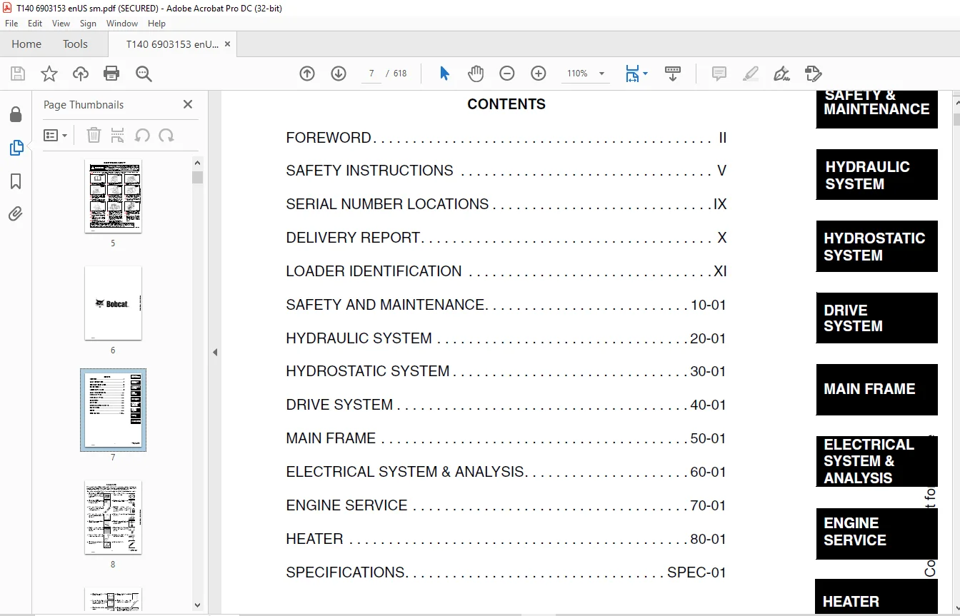
TABLE OF CONTENTS:
Bobcat T140 Loader Service Manual 6903153 (6-12) – PDF DOWNLOAD
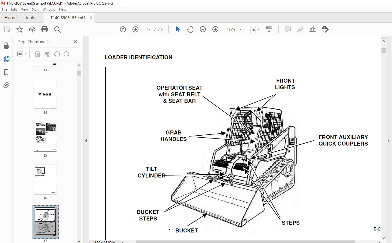
MAINTENANCE SAFETY..............................................................................  5
ALPHABETICAL INDEX..............................................................................  3
CONTENTS........................................................................................  7
	FOREWORD....................................................................................  8
	SAFETY INSTRUCTIONS......................................................................... 11
		Fire Prevention......................................................................... 13
	SERIAL NUMBER LOCATIONS..................................................................... 15
		Loader Serial Number.................................................................... 15
		Engine Serial Number.................................................................... 15
	DELIVERY REPORT............................................................................. 16
	LOADER IDENTIFICATION....................................................................... 17
SAFETY AND MAINTENANCE.......................................................................... 19
	LIFTING AND BLOCKING THE LOADER............................................................. 21
		Procedure............................................................................... 21
	LIFT ARM SUPPORT DEVICE..................................................................... 23
		Installing Lift Arm Support Device...................................................... 23
		Removing The Lift Arm Support Device.................................................... 24
	OPERATOR CAB................................................................................ 25
		Description............................................................................. 25
		Raising The Operator Cab................................................................ 25
		Lowering The Operator Cab............................................................... 26
		Emergency Exit.......................................................................... 27
	TRANSPORTING THE BOBCAT LOADER.............................................................. 29
		Procedure............................................................................... 29
	TOWING THE LOADER........................................................................... 31
		Procedure............................................................................... 31
	REMOTE START................................................................................ 33
		Procedure............................................................................... 33
	SERVICE SCHEDULE............................................................................ 37
		Chart................................................................................... 37
	AIR CLEANER SERVICE......................................................................... 39
		Checking................................................................................ 39
		Replacing Filter Element(s)............................................................. 40
	ENGINE COOLING SYSTEM....................................................................... 43
		Cleaning The Cooling System............................................................. 43
		Checking The Coolant Level.............................................................. 44
		Replacing The Coolant................................................................... 45
	FUEL SYSTEM................................................................................. 47
		Fuel Specifications..................................................................... 47
		Filling The Fuel Tank................................................................... 47
		Fuel Filter............................................................................. 48
		Removing Air From The Fuel System....................................................... 48
	ENGINE LUBRICATION SYSTEM................................................................... 49
		Checking Engine Oil..................................................................... 49
		Oil Chart............................................................................... 49
		Replacing Oil And Filter................................................................ 49
	HYDRAULIC/HYDROSTATIC SYSTEM................................................................ 51
		Checking And Adding Fluid............................................................... 51
		Replacing Hydraulic/Hydrostatic Filter.................................................. 51
		Replacing Hydrostatic Motor Case Drain Filter(s)........................................ 52
		Replacing Hydraulic Fluid............................................................... 53
		Breather Cap............................................................................ 54
	FAN GEARBOX................................................................................. 55
		Checking And Maintaining................................................................ 55
	BOB-TACH™................................................................................... 57
		Inspection And Maintenance.............................................................. 57
	POWER BOB-TACH™............................................................................. 59
		Inspection And Maintenance.............................................................. 59
	LUBRICATION OF THE BOBCAT LOADER............................................................ 61
		Procedure............................................................................... 61
	SPARK ARRESTOR MUFFLER...................................................................... 65
		Servicing............................................................................... 65
HYDRAULIC SYSTEM................................................................................ 67
	HYDRAULIC/HYDROSTATIC SCHEMATICS............................................................ 71
	HYDRAULIC SYSTEM INFORMATION................................................................ 73
		Glossary Of Hydraulic/Hydrostatic Symbols............................................... 73
		Tighten Procedures...................................................................... 77
		Troubleshooting Chart................................................................... 78
	CYLINDER (LIFT)............................................................................. 79
		Checking................................................................................ 79
		Removal And Installation................................................................ 80
		Identification.......................................................................... 81
		Disassembly............................................................................. 82
		Assembly................................................................................ 83
	CYLINDER (TILT)............................................................................. 87
		Checking................................................................................ 87
		Removal And Installation................................................................ 87
		Rod End Pivot Pin Bushing And Seal Replacement.......................................... 89
		Identification.......................................................................... 90
		Disassembly............................................................................. 91
		Assembly................................................................................ 92
	CYLINDER (POWER BOB-TACH™).................................................................. 95
		Checking................................................................................ 95
		Removal And Installation................................................................ 96
		Parts Identification.................................................................... 97
		Disassembly............................................................................. 98
		Assembly................................................................................ 99
	MAIN RELIEF VALVE...........................................................................103
		Checking................................................................................103
		Adjustment..............................................................................105
	HYDRAULIC CONTROL VALVE (FOOT CONTROL)......................................................107
		Removal And Installation................................................................107
		Identification Chart....................................................................112
		BICS Valve, Lift Load Check Valve Removal And Installation..............................113
		Load Check Valve Removal And Installation (Tilt & Auxiliary)............................114
		Anti-Cavitation Valve (Lift, Rod End)...................................................115
		Port Relief/Anti-Cavitation Valve (Lift, Base End)......................................116
		Port Relief/Anti-Cavitation Valve (Tilt, Base End)......................................116
		Port Relief/Anti-Cavitation Valve (Tilt, Rod End).......................................117
		Port Relief Valve.......................................................................118
		Plug Removal............................................................................119
		Rubber Boot Removal and Installation....................................................120
		End Cap/Spool Lock Block Removal and Installation.......................................121
		Lift Spool and Detent Removal and Installation..........................................122
		Tilt Spool Removal and Installation.....................................................132
		Auxiliary Spool Removal And Installation................................................134
		Auxiliary Solenoid Disassembly and Assembly.............................................136
		BICS Valve Solenoid Disassembly And Assembly............................................137
		BICS Valve, Lock Valve Removal And Installation.........................................138
		BICS Valve, Check Valve Removal And Installation........................................140
		BICS Valve, Lift Arm By-Pass Orifice Disassembly And Assembly...........................141
		Main Relief Valve.......................................................................141
	HYDRAULIC CONTROL VALVE (ADVANCED CONTROL SYSTEM) (ACS).....................................143
		Removal And Installation................................................................143
		Actuator Removal And Installation (Out of Loader).......................................147
		Identification Chart (ACS)..............................................................150
		BICS Valve, Load Check Valve Removal And Installation (Lift)............................151
		Load Check Valve Removal And Installation (Tilt & Auxiliary)............................152
		Anti-Cavitation Valve (Lift, Rod End)...................................................153
		Port Relief/Anti-Cavitation Valve (Lift, Base End)......................................154
		Port Relief/Anti-Cavitation Valve (Tilt, Base End)......................................154
		Port Relief/Anti-Cavitation Valve (Tilt, Rod End).......................................155
		Port Relief Valve.......................................................................156
		Plug Removal............................................................................157
		End Cap Block Removal and Installation..................................................158
		Lift Spool Removal and Installation.....................................................159
		Tilt Spool Removal and Installation.....................................................163
		Auxiliary Spool Removal And Installation................................................165
		Auxiliary Solenoid Disassembly and Assembly.............................................167
		BICS Valve Solenoid Disassembly And Assembly............................................168
		BICS Valve, Lock Valve Removal And Installation.........................................169
		BICS Valve, Check Valve Removal And Installation........................................171
		BICS Valve, Lift Arm By-Pass Orifice Disassembly And Assembly...........................172
		Main Relief Valve.......................................................................172
	LIFT ARM BY-PASS CONTROL VALVE..............................................................173
		Inspecting..............................................................................173
		Removal And Installation................................................................173
		Disassembly And Assembly................................................................174
	HYDRAULIC PUMP..............................................................................175
		Check The Output Of The Hydraulic Pump Without Rear Auxiliary...........................175
		Removal And Installation................................................................178
		Identification..........................................................................182
		Disassembly And Assembly................................................................183
	HYDRAULIC/HYDROSTATIC FILTER................................................................189
		Housing Removal And Installation........................................................189
	HYDRAULIC FLUID RESERVOIR...................................................................191
		Removal And Installation................................................................191
	BUCKET POSITION VALVE.......................................................................193
		Solenoid Removal And Installation.......................................................193
		Solenoid Testing........................................................................193
		Removal And Installation................................................................194
		Disassembly And Assembly................................................................195
	REAR AUXILIARY DIVERTER VALVE...............................................................199
		Removal And Installation................................................................199
		Disassembly And Assembly................................................................201
		Inspection..............................................................................206
	POWER BOB-TACH™ BLOCK.......................................................................207
		Removal And Installation................................................................207
		Disassembly And Assembly................................................................209
	FRONT AUXILIARY HYDRAULIC COUPLER BLOCK.....................................................213
		Removal and Installation................................................................213
		Disassembly And Assembly................................................................213
HYDROSTATIC SYSTEM..............................................................................215
	HYDROSTATIC SYSTEM INFORMATION..............................................................217
		Troubleshooting Chart...................................................................217
		Replenishing Valve Function.............................................................218
	HYDROSTATIC MOTOR...........................................................................219
		Replacing the Motor Oil.................................................................219
		Removal And Installation................................................................220
		Parts Identification....................................................................222
		Disassembly.............................................................................224
		Inspection..............................................................................232
		Assembly................................................................................233
	CHARGE PRESSURE.............................................................................243
		Sender Removal And Installation.........................................................243
		Checking Charge Pressure................................................................243
		Adjusting...............................................................................244
	HYDROSTATIC PUMP............................................................................245
		Replenishing/High Pressure Relief Valve.................................................245
		Removal And Installation................................................................246
		Parts Identification (Right Half).......................................................248
		Parts Identification (Left Half)........................................................250
		Hydraulic Pump Removal And Installation.................................................252
		Pump Separation.........................................................................252
		Disassembly.............................................................................253
		Assembly................................................................................259
	DRIVE BELT..................................................................................267
		Shield Removal And Installation.........................................................267
		Adjusting...............................................................................267
		Drive Belt Replacement..................................................................269
		Tensioner Pulley Removal And Installation...............................................270
		Tensioner Pulley Parts Identification...................................................271
		Tensioner Pulley Disassembly............................................................272
		Tensioner Pulley Assembly...............................................................273
	OIL COOLER..................................................................................275
		Removal and Installation................................................................275
DRIVE SYSTEM....................................................................................277
	BRAKE.......................................................................................279
		Pressure Relief Valve Test..............................................................279
		Right Motor Brake Test..................................................................280
		Left Motor Brake Test...................................................................281
		Block Removal And Installation..........................................................283
		Block Disassembly And Assembly..........................................................285
	DRIVE COMPONENTS............................................................................287
		Track Tension...........................................................................287
		Track Tension Adjusting.................................................................288
		Track Removal And Installation..........................................................290
		Track Idler (Front) Removal And Installation............................................293
		Track Idler (Front) Disassembly and Assembly............................................295
		Track Idler (Rear) End Play Specifications..............................................296
		Track Idler (Rear) Removal And Installation.............................................296
		Track Idler (Rear) Disassembly and Assembly.............................................296
		Track Roller Assembly End Play Specifications...........................................297
		Track Roller Removal And Installation...................................................297
		Track Roller Disassembly and Assembly...................................................297
		Track Housing Removal And Installation..................................................298
		Track Damage Identification.............................................................299
MAIN FRAME......................................................................................311
	SEAT BAR....................................................................................313
		Removal And Installation................................................................313
		Assembling Components...................................................................315
		Compression Spring Disassembly And Assembly.............................................317
	OPERATOR CAB................................................................................319
		Gas Cylinder Removal And Installation...................................................319
		Gas Cylinder Disassembly................................................................321
		Removal And Installation................................................................322
	OPERATOR SEAT...............................................................................325
		Removal And Installation................................................................325
		Slide Rail Removal And Installation.....................................................326
		Seat Belt Removal and Installation......................................................326
		Cushion Removal And Installation........................................................327
		Back Removal And Installation...........................................................328
		Shock Removal And Installation..........................................................328
		3-Point Seat Belt Removal And Installation..............................................329
	BOB-TACH™...................................................................................331
		Removal And Installation................................................................331
		Bob-Tach Lever And Wedge................................................................333
		Bob-Tach Stops..........................................................................334
	POWER BOB-TACH™.............................................................................335
		Removal And Installation................................................................335
		Power Bob-Tach Lever And Wedge..........................................................337
	LIFT ARM....................................................................................339
		Removal And Installation................................................................339
	REAR GRILL..................................................................................343
		Removal And Installation................................................................343
	REAR DOOR...................................................................................345
		Removal And Installation................................................................345
		Striker Removal and Installation........................................................346
		Striker Disassembly and Assembly........................................................346
		Door Latch and Catch Adjustment.........................................................346
		Latch Removal And Installation..........................................................347
	FUEL TANK...................................................................................349
		Removal And Installation................................................................349
		Fuel Level Sender.......................................................................350
		Fuel Fill Screen........................................................................350
		Fuel Pickup Screen......................................................................351
	CONTROL PEDALS..............................................................................353
		Removal And Installation................................................................353
		Pedal Adjustment........................................................................353
		Crossbar Linkage Removal And Installation...............................................354
		Lift Foot Pedal Linkage Removal And Installation........................................355
		Tilt Foot Pedal Linkage Removal And Installation........................................355
	CONTROL PEDALS (ACS)........................................................................357
		Foot Sensor Removal And Installation....................................................357
		Foot Pedal Removal And Installation.....................................................358
		Foot Pedal Linkage Disassembly And Assembly.............................................358
	CONTROL PANEL...............................................................................359
		Description.............................................................................359
		Removal and Installation................................................................360
		Shock Removal And Installation..........................................................363
		Shaft Removal And Installation..........................................................363
		Shaft Disassembly And Assembly..........................................................364
		Linkage Removal And Installation........................................................365
		Pintle Arm Disassembly and Assembly.....................................................369
		Linkage Neutral Adjustment..............................................................371
		Linkage Travel Adjustment...............................................................375
	CONTROL HANDLE..............................................................................379
		Control Lever Removal And Installation..................................................379
		Rubber Boot Replacement.................................................................379
	CONTROL HANDLE (ADVANCED CONTROL SYSTEM) (ACS) SELECTABLE HAND/FOOT CONTROL.................381
		Components Identification...............................................................381
		Handle Sensor Removal And Installation..................................................381
		Control Handle Removal and Installation.................................................384
		Control Handle Disassembly and Assembly.................................................385
		Control Lever Removal and Installation..................................................385
		Control Lever Boot......................................................................386
ELECTRICAL SYSTEM & ANALYSIS....................................................................387
	ELECTRICAL SCHEMATICS.......................................................................391
	ELECTRICAL SYSTEM INFORMATION...............................................................395
		Troubleshooting Chart...................................................................395
		Description.............................................................................396
		Relay Switch Location...................................................................397
		Fuse Location...........................................................................397
	BATTERY.....................................................................................399
		Removal And Installation................................................................399
		Servicing...............................................................................400
		Using A Booster Battery (Jump Starting).................................................401
	ALTERNATOR..................................................................................403
		Adjusting The Alternator Belt...........................................................403
		Alternator Identification...............................................................403
		Charging System Check...................................................................404
		Alternator Voltage Test.................................................................405
		Low Voltage Test........................................................................405
		High Voltage Test.......................................................................406
		Removal And Installation................................................................407
		Rectifier Continuity (Diode) Test.......................................................408
		Alternator Regulator Test...............................................................409
		Disassembly.............................................................................409
		Stator Continuity Test..................................................................410
		Stator Ground Test......................................................................410
		Rotor Continuity Test...................................................................410
		Rotor Ground Test.......................................................................410
		Assembly................................................................................411
	STARTER.....................................................................................413
		Checking................................................................................413
		Removal And Installation................................................................414
		Parts Identification....................................................................415
		Disassembly and Assembly................................................................416
		Inspection And Repair...................................................................419
		No Load Test............................................................................421
	INSTRUMENT PANEL............................................................................423
		Left Panel..............................................................................423
		Right Panel (Standard) (With Key Switch)................................................424
		Right Panel - (Deluxe) (With Keyless Start).............................................424
		Right Panel Setup Display Options (Deluxe)..............................................427
		Option And Field Accessory Panels (If Equipped).........................................430
		Removal And Installation................................................................431
		Front Accessory Panel Removal And Installation..........................................432
	LIGHTS......................................................................................433
		Front Removal And Installation..........................................................433
		Rear Removal And Installation...........................................................434
	BOBCAT CONTROLLER...........................................................................435
		Identification Chart....................................................................435
		Removal And Installation................................................................437
	DIAGNOSTIC SERVICE CODES....................................................................439
		Display.................................................................................439
		Number Codes List.......................................................................440
	BICS SYSTEM.................................................................................445
		Inspecting The BICS Controller (Engine STOPPED - Key ON)................................445
		Inspecting Deactivation Of The Auxiliary Hydraulics System (Engine STOPPED - Key ON)....445
		Inspecting The Seat Bar Sensor (Engine RUNNING).........................................445
		Inspecting The Traction Lock (Engine RUNNING)...........................................445
		Inspecting The Lift Arm By-Pass Control.................................................445
		Troubleshooting Chart...................................................................446
		Troubleshooting Guide...................................................................447
	SEAT BAR SENSOR.............................................................................449
		Troubleshooting Chart...................................................................449
		Test....................................................................................450
		Removal And Installation................................................................451
		BICS Circuit Test.......................................................................452
	TRACTION LOCK...............................................................................453
		Troubleshooting Chart...................................................................453
		Description Of The Control System.......................................................454
		Inspecting The Control System...........................................................454
	ADVANCED CONTROL SYSTEM (ACS) SELECTABLE HAND/FOOT CONTROL..................................455
		Components Identification...............................................................455
		Troubleshooting Guide...................................................................457
		Controller, Connector And Wire Identification...........................................458
		ACS Controller Removal And Installation.................................................459
		Handle Sensor Connector.................................................................459
		Switch Handle Removal...................................................................460
		Switch Handle Installation..............................................................462
		Actuators Disassembly And Assembly......................................................465
		Handle Lock Solenoid Removal And Installation...........................................466
		Handle Lock Solenoid Disassembly And Assembly...........................................466
		Handle Lock Solenoid Connector..........................................................467
		Calibration Of The ACS System...........................................................468
		Switchable Hand/Foot Controls Calibration Procedure.....................................468
		Foot Sensor Disassembly And Assembly....................................................470
		Foot Sensor Connector...................................................................470
		Foot Lock Solenoid Removal And Installation.............................................471
		Foot Lock Solenoid Connector............................................................471
	ELECTRICAL/HYDRAULIC CONTROLS REFERENCE.....................................................473
		Controls Identification Chart...........................................................473
	FLYWHEEL RPM SENSOR.........................................................................475
		Adjustment..............................................................................475
ENGINE SERVICE..................................................................................477
	TROUBLESHOOTING.............................................................................479
		Chart...................................................................................479
	ENGINE SPEED CONTROL........................................................................481
		Removal And Installation................................................................481
		Disassembly.............................................................................481
	MUFFLER.....................................................................................483
		Removal And Installation................................................................483
	AIR CLEANER.................................................................................485
		Removal And Installation................................................................485
	RADIATOR....................................................................................487
		Removal And Installation................................................................487
	COOLING FAN.................................................................................489
		Drive Tension Pulley Removal And Installation...........................................489
		Gearbox/Blower Housing Removal And Installation.........................................490
		Blower Housing Grill Removal And Installation...........................................492
		Blower Disassembly And Assembly.........................................................492
		Gearbox Parts Identification............................................................494
		Gearbox Disassembly.....................................................................495
		Gearbox Assembly........................................................................500
		Gearbox Checking Backlash...............................................................504
	ENGINE COMPONENTS AND TESTING...............................................................509
		Compression Checking....................................................................509
		Glow Plugs Checking.....................................................................510
		Glow Plugs Removal And Installation.....................................................510
		Fuel Shutoff Solenoid, Checking.........................................................511
		Fuel Shutoff Solenoid Removal And Installation..........................................512
		Fuel Injection Pump Removal And Installation............................................513
		Timing The Injection Pump...............................................................517
		Fuel Injector Removal And Installation..................................................518
		Checking Nozzle Injection Pressure......................................................520
		Nozzle Spraying Condition...............................................................520
		Valve Seat Tightness....................................................................521
		Valve Clearance Adjustment..............................................................521
		Valve Timing, Checking..................................................................522
	ENGINE......................................................................................523
		Removal And Installation................................................................523
		Engine Mount Replacement................................................................529
	FLYWHEEL AND HOUSING........................................................................531
		Flywheel Removal And Installation.......................................................531
		Ring Gear Removal And Installation......................................................531
		Housing Removal And Installation........................................................532
	RECONDITIONING THE ENGINE...................................................................535
		Cylinder Head Removal And Installation..................................................535
		Cylinder Head Disassembly And Assembly..................................................538
		Cylinder Head Servicing.................................................................539
		Cylinder Head Top Clearance.............................................................539
		Valve Guide Checking....................................................................540
		Reconditioning The Valve And Valve Seat.................................................542
		Valve Spring............................................................................543
		Rocker Arm And Shaft Checking...........................................................544
		Timing Gearcase Cover Removal And Installation..........................................544
		Idler Gear And Camshaft Removal And Installation........................................547
		Camshaft Servicing......................................................................548
		Idler Gear And Shaft Servicing..........................................................549
		Timing Gears Checking Backlash..........................................................550
		Fuel Camshaft Removal And Installation..................................................550
		Fuel Camshaft Governor..................................................................551
		Crankshaft Gear Removal And Installation................................................551
		Oil Pump Removal And Installation.......................................................552
		Oil Pump Service........................................................................552
		Checking Engine Oil Pressure............................................................553
		Valve Tappets...........................................................................554
		Piston And Connecting Rod Removal And Installation......................................554
		Piston And Connecting Rod Servicing.....................................................556
		Connecting Rod Alignment................................................................558
		Crankshaft And Bearings Removal And Installation........................................559
		Crankshaft And Bearings, Servicing......................................................561
		Cylinder Bore, Checking.................................................................565
		Water Pump Removal And Installation.....................................................565
		Water Pump Disassembly And Assembly.....................................................566
HEATER..........................................................................................567
	COMPONENTS..................................................................................569
		Identification..........................................................................569
	REGULAR MAINTENANCE.........................................................................571
		Filter Elements Removal And Installation................................................571
	BASIC TROUBLESHOOTING.......................................................................573
		Cleaning The Heater Coil................................................................573
		Checking The Electrical System..........................................................574
		Engine Coolant By-Passing The Heater Valve..............................................578
		Heater Valve Not Opening Or Closing.....................................................579
	SYSTEM TROUBLESHOOTING CHART................................................................581
		Blower Motor Does Not Operate...........................................................581
		Blower motor operators normally, but air flow is insufficient...........................581
	HEATER UNIT.................................................................................583
		Removal And Installation................................................................583
		Disassembly And Assembly................................................................584
	HEATER COIL.................................................................................585
		Removal And Installation................................................................585
	HEATER FAN..................................................................................587
		Removal And Installation................................................................587
		Disassembly And Assembly................................................................587
		Wire Connector Removal and Installation.................................................589
	HEATER VALVE................................................................................591
		Removal and Installation................................................................591
		Disassembly And Assembly................................................................592
SPECIFICATIONS..................................................................................593
	LOADER SPECIFICATIONS (T140)................................................................595
		Machine Dimensions......................................................................595
		Performance.............................................................................596
		Controls................................................................................596
		Engine..................................................................................596
		Hydraulic System........................................................................597
		Electrical..............................................................................598
		Drive System............................................................................598
		Capacities..............................................................................598
		Tracks..................................................................................598
		Ground Pressure.........................................................................598
	ENGINE SPECIFICATIONS.......................................................................599
		Fuel Injection Nozzles..................................................................599
		Fuel Injection Pump.....................................................................599
		Cylinder Head...........................................................................599
		Valves..................................................................................599
		Valve Springs...........................................................................600
		Valve Timing............................................................................600
		Rocker Arms.............................................................................600
		Camshaft................................................................................600
		Tappet..................................................................................600
		Cylinders...............................................................................601
		Piston Rings............................................................................601
		Pistons.................................................................................601
		Connecting Rod..........................................................................601
		Oil Pump................................................................................601
		Crankshaft..............................................................................602
		Timing Gear.............................................................................602
		Thermostat..............................................................................602
	TORQUE SPECIFICATIONS FOR BOLTS.............................................................603
		Torque For General SAE Bolts............................................................603
		Torque For General Metric Bolts.........................................................604
		Torque For Kubota Metric Bolts..........................................................604
	HYDRAULIC CONNECTION SPECIFICATIONS.........................................................605
		O-ring Face Seal Connection.............................................................605
		Straight Thread O-ring Fitting..........................................................606
		Tubelines And Hoses.....................................................................606
		Flare Fitting...........................................................................606
		O-ring Flare Fitting....................................................................607
		Port Seal Fitting.......................................................................609
	HYDRAULIC FLUID SPECIFICATIONS..............................................................611
		Specifications..........................................................................611
	CONVERSIONS.................................................................................613
		Decimal And Millimeter Equivalents......................................................613
		U.S. To Metric Conversion...............................................................613
SMR.............................................................................................615
	T140-1......................................................................................615
	T140-2
.....................................................................................617
Contact us: [email protected]
PLEASE NOTE:
- This is not a physical manual but a digital manual – meaning no physical copy will be couriered to you. The manual can be yours in the next 2 mins as once you make the payment, you will be directed to the download page IMMEDIATELY.
- This is the same manual used by the dealers inorder to diagnose your vehicle of its faults.
- Require some other service manual or have any queries: please WRITE to us at [email protected]
S.V