Bobcat T190 Track Loader Service Manual 6904146 (8-09) PDF File Download
$33.95
Bobcat T190 Track Loader Service Manual 6904146 (8-09) – PDF DOWNLOAD
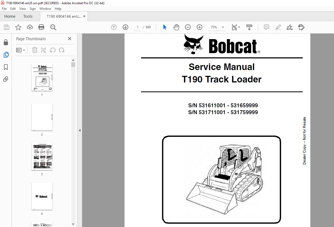
S/N 531611001 – 531659999
S/N 531711001 – 531759999
Description
Bobcat T190 Track Loader Service Manual 6904146 (8-09) – PDF DOWNLOAD
FILE DETAILS:
Bobcat T190 Track Loader Service Manual 6904146 (8-09) – PDF DOWNLOAD
Language : English
Pages : 899
Downloadable : Yes
File Type : PDF
DESCRIPTION:
Bobcat T190 Track Loader Service Manual 6904146 (8-09) – PDF DOWNLOAD
S/N 531611001 – 531659999
S/N 531711001 – 531759999
FOREWORD:
This manual is for the Bobcat loader mechanic. It provides necessary servicing and adjustment procedures for the Bobcat loader and its component parts and systems. Refer to the Operation & Maintenance Manual for operating instructions, starting procedure, daily checks, etc.
A general inspection of the following items must be made after the loader has had service or repair:
IMAGES PREVIEW OF THE MANUAL:
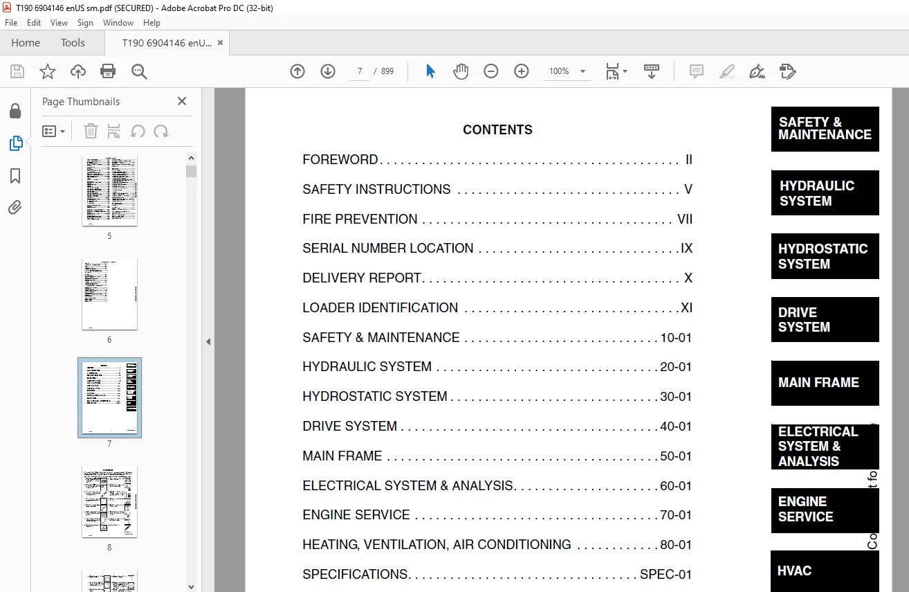
TABLE OF CONTENTS:
Bobcat T190 Track Loader Service Manual 6904146 (8-09) – PDF DOWNLOAD
MAINTENANCE SAFETY 3
ALPHABETICAL INDEX 5
CONTENTS 7
FOREWORD 8
SAFETY INSTRUCTIONS 11
FIRE PREVENTION 13
Maintenance 13
Operation 13
Electrical 13
Hydraulic System 13
Fueling 13
Starting 13
Spark Arrestor Exhaust System 13
Welding And Grinding 14
Fire Extinguishers 14
SERIAL NUMBER LOCATION 15
Loader Serial Number 15
Engine Serial Number 15
DELIVERY REPORT 16
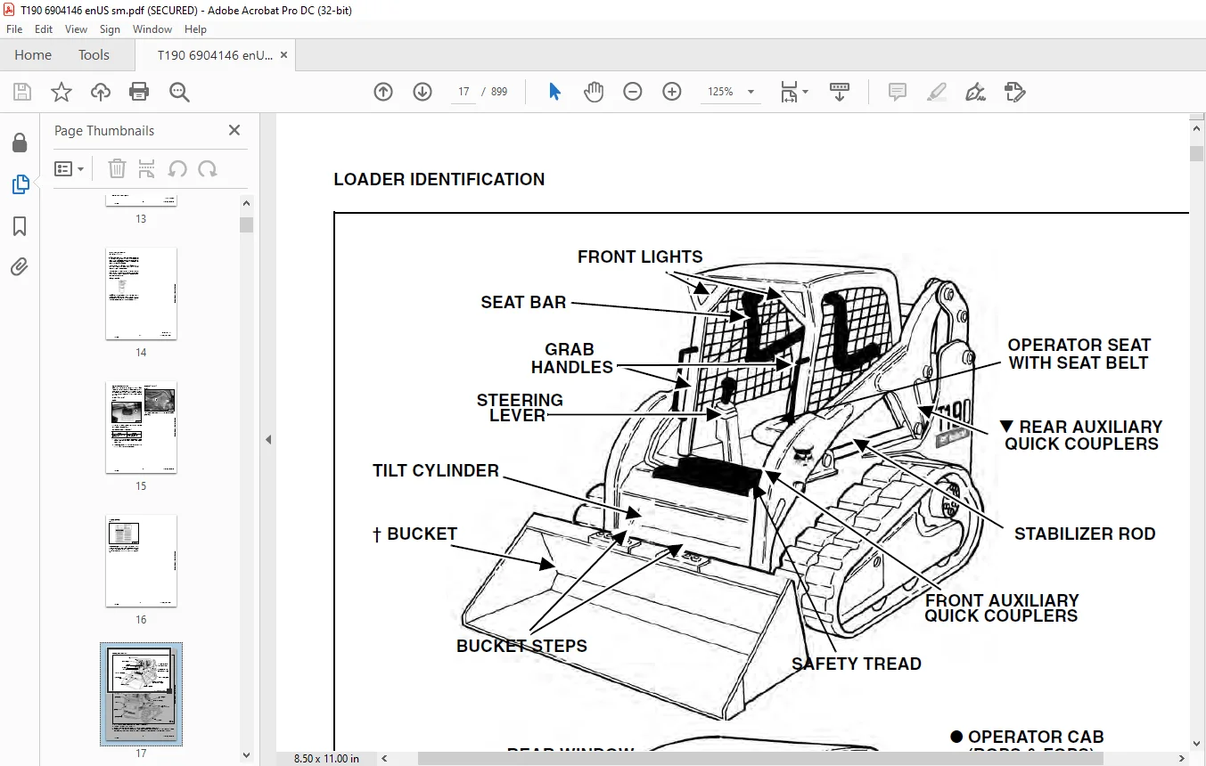
LOADER IDENTIFICATION 17
SAFETY & MAINTENANCE 19
LIFTING AND BLOCKING THE LOADER 21
Procedure 21
LIFT ARM SUPPORT DEVICE 23
Installing 23
Removing 24
OPERATOR CAB 25
Description 25
Raising 26
Lowering 27
Cab Door Sensor 28
Special Applications Kit 28
Special Applications Kit Inspection And Maintenance 28
TRANSPORTING THE LOADER ON A TRAILER 29
Loading And Unloading 29
Fastening 29
TOWING THE LOADER 31
Procedure 31
REMOTE START TOOL KIT-MEL1563 33
Remote Start Tool – MEL1563 33
Service Tool Harness Control – MEL1565 34
Service Tool Harness Communicator – MEL1566 35
Remote Start Procedure 36
REMOTE START TOOL (SERVICE TOOL) KIT – 6689779 39
Description 39
Remote Start Tool (Service Tool) – 6689778 40
Loader Service Tool Harness – 6689747 41
Computer Service Tool Harness – 6689746 42
Remote Start Procedure 43
SERVICE SCHEDULE 47
Chart 47
AIR CLEANER SERVICE 49
Replacing Filter Elements 49
ENGINE COOLING SYSTEM 51
Cleaning 51
Checking Level 52
Removing And Replacing Coolant 52
FUEL SYSTEM 53
Fuel Specifications 53
Biodiesel Blend Fuel 53
Filling The Fuel Tank 54
Fuel Filter 55
Removing Air From The Fuel System 55
ENGINE LUBRICATION SYSTEM 57
Checking And Adding Engine Oil 57
Engine Oil Chart 57
Removing And Replacing Oil And Filter 57
HYDRAULIC/HYDROSTATIC SYSTEM 59
Checking And Adding Fluid 59
Hydraulic / Hydrostatic Fluid Chart 59
Removing And Replacing Hydraulic Fluid 60
Removing And Replacing Hydraulic / Hydrostatic Filter 61
Removing And Replacing Case Drain Filters 62
Removing And Replacing Hydraulic Charge Filter 63
Breather Cap 64
BOB-TACH (HAND LEVER) 65
Inspection And Maintenance 65
BOB-TACH (POWER) 67
Inspection And Maintenance 67
LUBRICATING THE LOADER 69
Lubrication Locations 69
SPARK ARRESTOR MUFFLER 71
Cleaning Procedure 71
PIVOT PINS 73
Inspection And Maintenance 73
LOADER STORAGE AND RETURN TO SERVICE 75
Storage 75
Return to Service 75
STOPPING THE ENGINE AND LEAVING THE LOADER 77
Procedure 77
Emergency Exit 78
HYDRAULIC SYSTEM 79
HYDRAULIC / HYDROSTATIC SCHEMATICS 85
HYDRAULIC SYSTEM INFORMATION 93
Glossary Of Hydraulic / Hydrostatic Symbols 93
Troubleshooting 97
CYLINDER (LIFT) 99
Testing 99
Removal And Installation 100
Parts Identification 103
Disassembly And Assembly 104
CYLINDER (TILT) 107
Testing 107
Removal And Installation 108
Base End Pivot Pin Removal And Installation 109
Rod End Pivot Pin Bushing And Seal Removal And Installation 110
Parts Identification 111
Disassembly And Assembly 112
CYLINDER (BOB-TACH) 115
Testing 115
Removal And Installation 116
Parts Identification 117
Disassembly And Assembly 118
MAIN RELIEF VALVE 121
Description 121
Testing 121
Adjusting 123
Removal And Installation 124
HYDRAULIC CONTROL VALVE (STANDARD) 125
Description 125
Removal And Installation 125
Identification Chart 130
Mount Bracket Removal And Installation 131
Lift Load Check Valve Removal And Installation 131
Load Check Valve Removal And Installation (Tilt & Auxiliary) 132
Anti-Cavitation Valve Removal And Installation (Lift, Rod End) 133
Port Relief/Anti-Cavitation Valve Removal And Installation (Lift, Base End) 134
Port Relief/Anti-Cavitation Valve Removal And Installation (Tilt, Base End) 134
Port Relief/Anti-Cavitation Valve Removal And Installation (Tilt, Rod End) 135
Port Relief Valve Removal And Installation 135
Plug Removal And Installation 136
Rubber Boot Removal And Installation 137
End Cap/Spool Lock Block Removal And Installation 138
Lift Spool And Detent Removal And Installation 139
Tilt Spool Removal And Installation 149
Auxiliary Spool Removal And Installation 151
Auxiliary Solenoid Removal And Installation 152
Solenoid Removal And Installation 153
Lock Valve Removal And Installation 155
Lift Arm Bypass Orifice Removal And Installation 157
Main Relief Valve Removal And Installation 157
Check Valve Removal And Installation 158
HYDRAULIC CONTROL VALVE (ACS) OR (SJC) 159
Description 159
Removal And Installation 159
Actuator Removal And Installation (Out of Loader) 164
Identification Chart 167
Mount Bracket Removal And Installation 168
Lift Load Check Valve Removal And Installation 168
Load Check Valve Removal And Installation (Tilt & Auxiliary) 169
Anti-Cavitation Valve Removal And Installation (Lift, Rod End) 170
Port Relief/Anti-Cavitation Valve Removal And Installation (Lift, Base End) 171
Port Relief/Anti-Cavitation Valve Removal And Installation (Tilt, Base End) 171
Port Relief/Anti-Cavitation Valve Removal And Installation (Tilt, Rod End) 172
Port Relief Valve Removal And Installation 172
Plug Removal And Installation 173
End Cap Block Removal And Installation 174
Lift Spool And Detent Removal And Installation 175
Tilt Spool Removal And Installation 180
Auxiliary Spool Removal And Installation 182
Auxiliary Solenoid Removal And Installation 183
Solenoid Removal And Installation 184
Lock Valve Removal And Installation 186
Lift Arm Bypass Orifice Removal And Installation 188
Main Relief Valve Removal And Installation 189
Check Valve Removal And Installation 190
LIFT ARM BYPASS CONTROL VALVE 191
Description 191
Testing 191
Removal and Installation 191
Disassembly And Assembly 192
HYDRAULIC PUMP (STANDARD) 193
Description 193
Pump Test at Quick Couplers 193
Direct Pump Test (Standard Section) 194
Direct Pump Test (Charge Section) 196
Removal And Installation 198
Hydraulic Pump Start Up 200
Parts Identification 201
Disassembly And Assembly 202
HYDRAULIC PUMP (STANDARD) (HIGH FLOW) 211
Description 211
Pump Test at Quick Couplers 211
Direct Pump Test (Standard Section) 212
Direct Pump Test (Charge Section) 214
Direct Pump Test (High Flow Section) 216
Removal And Installation 218
Hydraulic Pump Start Up 220
Parts Identification 221
Disassembly And Assembly 222
HYDRAULIC PUMP (SJC) 235
Description 235
Pump Test at Quick Couplers 235
Direct Pump Test (Standard Section) 236
Direct Pump Test (Charge Section) 238
Removal And Installation 240
Hydraulic Pump Start Up 242
Parts Identification 243
Disassembly And Assembly 244
HYDRAULIC PUMP (SJC) (HIGH FLOW) 253
Description 253
Pump Test at Quick Couplers 253
Direct Pump Test (Standard Section) 254
Direct Pump Test (Charge Section) 256
Direct Pump Test (High Flow Section) 258
Removal And Installation 260
Hydraulic Pump Start Up 262
Parts Identification 263
Disassembly And Assembly 264
HYDRAULIC/HYDROSTATIC FILTERS 277
Description 277
Housing Removal And Installation 277
Charge Filter Housing Removal And Installation 279
HYDRAULIC FLUID RESERVOIR 281
Description 281
Removal And Installation 281
OIL COOLER 285
Description 285
Removal and Installation 285
BUCKET POSITION VALVE 287
Description 287
Solenoid Removal And Installation 287
Solenoid Testing 288
Removal And Installation 289
Disassembly And Assembly 290
REAR AUXILIARY DIVERTER VALVE 293
Description 293
Removal And Installation 293
Disassembly And Assembly 296
Solenoid Testing 302
BOB-TACH (POWER) BLOCK 303
Description 303
Removal And Installation 303
Disassembly And Assembly 305
FRONT AUXILIARY HYDRAULIC COUPLER BLOCK 309
Description 309
Removal and Installation 309
Disassembly And Assembly 309
HIGH FLOW VALVE 311
Description 311
High Flow Relief Valve Testing 311
High Flow Relief Valve Adjustment 313
Solenoid Testing 314
Removal And Installation 315
Disassembly And Assembly 316
HYDROSTATIC SYSTEM 319
HYDROSTATIC SYSTEM INFORMATION 321
Troubleshooting 321
Description 322
HYDROSTATIC MOTOR 323
Description 323
Removing And Replacing Oil 324
Removal And Installation 326
Parts Identification 328
Disassembly And Assembly 330
CHARGE PRESSURE 341
Description 341
Testing 341
Sender Removal And Installation 343
Adjusting 344
HYDROSTATIC PUMP 347
Description 347
Removal And Installation 348
Hydrostatic Pump Start Up 350
Replenishing/High Pressure Relief Valve 350
Parts Identification (Left Half) 352
Parts Identification (Right Half) 353
Disassembly 354
Assembly 360
HYDROSTATIC PUMP (SJC) 367
Description 367
Hydraulic Controller Removal And Installation 368
Removal And Installation 370
Hydrostatic Pump Start Up 372
Parts Identification 373
High Pressure Relief and Bypass Valve 374
Charge Relief Valve 375
Disassembly And Assembly 376
Mechanical Neutral Adjustment 392
Hydraulic Controller Neutral Adjustment 395
DRIVE BELT 399
Description 399
Shield Removal And Installation 399
Adjusting 400
Belt Removal And Installation 401
Belt Tensioner Removal And Installation 402
Belt Tensioner Parts Identification 403
Belt Tensioner Disassembly 404
Belt Tensioner Assembly 405
CASE DRAIN FILTER 407
Description 407
Disassembly And Assembly 407
DRIVE SYSTEM 409
BRAKE 411
Description 411
Right Motor Brake Test 411
Left Motor Brake Test 412
Block Removal And Installation 413
Block Disassembly And Assembly 415
TRACK CARRIAGE COMPONENTS 417
Description 417
Checking Tension 417
Adjusting Tension 417
Track Removal And Installation 420
Idler (Front) Removal And Installation 423
Idler (Rear) Removal And Installation 425
Roller Removal And Installation 425
Sprocket Removal And Installation 426
Carriage Removal And Installation 427
Track Damage Identification 429
MAIN FRAME 441
SEAT BAR 445
Description 445
Removal And Installation 445
Disassembly And Assembly 446
Compression Spring Disassembly And Assembly 448
OPERATOR CAB 449
Gas Cylinder Removal And Installation 449
Gas Cylinder Bracket Disassembly And Assembly 451
Removal And Installation 452
OPERATOR SEAT (SUSPENSION) 455
Removal And Installation 455
Slide Rail Removal And Installation 456
Seat Belt Removal and Installation 456
Lower Cushion Removal And Installation 456
Back Cushion Removal And Installation 458
Shock Removal And Installation 458
3-Point Seat Belt Removal And Installation 459
BOB-TACH (HAND LEVER) 461
Description 461
Removal And Installation 461
Lever And Wedge Disassembly And Assembly 462
Pivot Pin Bushing And Seal Removal And Installation 464
BOB-TACH (POWER-OPTION) 465
Description 465
Removal And Installation 465
Lever And Wedge Disassembly And Assembly 467
Pivot Pin Bushing And Seal Removal And Installation 468
LIFT ARMS 469
Stabilizer Bar Removal And Installation 469
Link Removal And Installation 470
Removal And Installation 471
REAR GRILL 475
Removal And Installation 475
REAR DOOR 477
Removal And Installation 477
Striker Removal and Installation 478
Striker Disassembly and Assembly 478
Striker (Adjusting) 478
Latch Removal and Installation 479
FUEL TANK 481
Removal And Installation 481
Fuel Level Sender Removal And Installation 482
Fuel Fill Screen Removal And Installation 482
CONTROL PEDALS AND LINKAGES 483
Description 483
Pedal Removal And Installation 483
Linkage Removal And Installation 484
Pedal (Adjusting) 486
CONTROL PEDALS (ACS) 487
Description 487
Foot Sensor Removal And Installation 487
Foot Pedal Removal And Installation 488
Foot Pedal Linkage Disassembly And Assembly 489
CONTROL PANEL 491
Description 491
Removal And Installation 492
Shock Removal And Installation 495
Shaft Removal And Installation 495
Shaft Disassembly And Assembly 496
Linkage Removal And Installation 497
Pintle Arm Disassembly And Assembly 501
Linkage Neutral Adjustment 503
Linkage Travel Adjustment 507
CONTROL PANEL (SJC) 511
Description 511
Removal And Installation 511
CONTROL HANDLE/LEVER 513
Description 513
Lever Removal And Installation 513
Boot Removal And Installation 514
CONTROL HANDLE/LEVER (ACS) 515
Description 515
Handle Sensor Removal And Installation 515
Handle Removal And Installation 518
Handle Disassembly And Assembly 519
Lever Removal And Installation 519
Boot Removal And Installation 521
CONTROL HANDLE/LEVER (SJC) 523
Description 523
Joystick Testing 523
Joystick Removal And Installation (S/N 531611001 – 531614844, S/N 531711001 – 531711281) 524
Joystick Removal And Installation (S/N 531614845 & Above, S/N 531711282 & Above) 526
Removal And Installation (S/N 531611001 – 531614844, S/N 531711001 – 531711281) 527
Removal And Installation (S/N 531614845 & Above, S/ N 531711282 & Above) 528
ACCESS PANEL (INSIDE) 529
Removal And Installation (Left) 529
Removal And Installation (Right) 529
ACCESS PANEL (INSIDE) (SJC) 531
Removal And Installation (Left) 531
Removal And Installation (Right) 532
WINDOW (REAR) 535
Removal 535
Installation 535
WINDOW (TOP) 537
Removal And Installation 537
WINDOW (SIDE) 539
Removal And Installation 539
WINDOW (FRONT DOOR) 541
Removal (Standard Window) 541
Installation (Standard Window) 542
Removal And Installation (Special Applications Window) 544
ELECTRICAL SYSTEM & ANALYSIS 545
ELECTRICAL SCHEMATICS 549
ELECTRICAL SYSTEM INFORMATION 562
Glossary Of Electrical Symbols 562
Cab Harness Connectors 565
Mainframe Harness Connectors 566
Description 567
Troubleshooting 568
Fuse And Relay Location / Identification 569
Solenoid Testing 570
BATTERY 572
Removal And Installation 572
Servicing 573
Using A Booster Battery (Jump Starting) 574
ALTERNATOR 576
Belt Adjustment 576
Belt Replacement 576
Charging System Inspection 577
Alternator Voltage Testing 578
Low Voltage Testing 578
High Voltage Testing 579
Removal And Installation 580
Parts Identification 581
STARTER 582
Testing 582
Removal And Installation 583
Parts Identification 584
INSTRUMENT PANELS 586
Left Panel 586
Right Panel (Key Switch) 587
Right Panel (Keyless) 588
Side And Front Panels 590
Removal And Installation (Left And Right) 591
Bulb Removal And Installation (Left Only) 594
Key Switch Removal And Installation 595
Alarm Removal And Installation 596
Front Panel Removal And Installation 596
LIGHTS 598
Front Removal And Installation 598
Rear Removal And Installation 599
Cab Light Removal And Installation 599
BOBCAT CONTROLLER (MAIN) 600
Description 600
Connector Identification 601
Removal And Installation 603
BOBCAT CONTROLLER (ACS) 604
Description 604
Connector Identification 606
Removal And Installation 607
BOBCAT CONTROLLER (SJC) (DRIVE) 608
Description 608
Connector Identification 609
Removal And Installation 611
SPEED SENSOR (SJC) 614
Description 614
Testing 614
Removal And Installation 616
DIAGNOSTIC SERVICE CODES 620
Viewing Service Codes (Key Switch) 620
Viewing Service Codes (Keyless) 620
Service Codes List 621
BOBCAT INTERLOCK CONTROL SYSTEM (BICS) 626
Description 626
Inspecting The BICS Controller (Engine STOPPED – Key ON) 627
Inspecting Deactivation Of The Auxiliary Hydraulics System (Engine STOPPED – Key ON) 627
Inspecting The Seat Bar Sensor (Engine RUNNING) 627
Inspecting The Traction Lock (Engine RUNNING) 627
Inspecting The Lift Arm Bypass Control 627
Inspecting Deactivation Of Lift And Tilt Functions (ACS and SJC) 627
Troubleshooting 628
Troubleshooting Chart 629
SEAT BAR SENSOR 630
Description 630
Troubleshooting 630
Testing 631
Removal And Installation 632
Bobcat Interlock Control System (BICS) Circuit Test 634
TRACTION LOCK 636
Description 636
Troubleshooting 637
Inspecting 638
CONTROL SYSTEM (ACS) 640
Description 640
Troubleshooting Chart 641
Handle Sensor Connector Disassembly And Assembly 642
Switch Handle Removal 643
Switch Handle Installation 645
Actuator Connector Disassembly And Assembly 648
Handle Lock Solenoid Removal And Installation 649
Handle Lock Solenoid Disassembly And Assembly 649
Foot Sensor Disassembly And Assembly 650
Foot Lock Solenoid Removal And Installation 651
ELECTRICAL/HYDRAULIC CONTROLS 652
Identification Chart 652
ELECTRICAL/HYDRAULIC CONTROLS REFERENCE (SJC) 654
Identification Chart 654
SERVICE PC (LAPTOP COMPUTER) 658
Connecting To The Remote Start Tool 658
Connecting Remote Start Tool (Service Tool) 658
CALIBRATION 660
Description 660
Actuator Testing 660
Lift And Tilt Calibration (ACS) 662
Lift And Tilt Calibration (SJC) 664
Hydrostatic Pump Calibration (SJC) 666
STEERING DRIFT COMPENSATION 672
Description 672
Selecting And Adjusting 672
Exiting And Saving 673
FLYWHEEL RPM SENSOR 674
Description 674
Adjusting 674
CONTROL PANEL SETUP 676
Right Panel Setup (Keyless) 676
Attachment Control Information (Keyless) 677
PASSWORD SETUP (IF EQUIPPED WITH KEYLESS START) 678
Password Description 678
Changing The Owner And User Passwords 679
Password Lockout Feature 680
MAINTENANCE CLOCK 682
Description 682
Setup 683
Reset 687
BACK-UP ALARM SYSTEM 688
Description 688
Inspecting 688
Adjusting Switch Position 689
Troubleshooting (Standard And ACS) 690
Troubleshooting (Joystick) 691
Alarm Removal And Installation 692
Switch Removal And Installation 692
ENGINE SERVICE 694
ENGINE INFORMATION 698
Description 698
Engine Specifications 699
Engine Torque Values 703
Troubleshooting 703
Removal And Installation 705
Engine Mount Replacement 712
Compression – Checking 713
ENGINE SPEED CONTROL 714
Removal And Installation 714
ENGINE SPEED CONTROL (SJC) 716
Removal And Installation 716
Disassembly And Assembly 718
MUFFLER 720
Removal And Installation 720
AIR CLEANER 722
Housing Removal And Installation 722
ENGINE COOLING SYSTEM 724
Radiator Removal And Installation 724
Blower Housing Removal And Installation 727
Hydraulic Fan Removal And Installation 729
Hydraulic Fan Description 730
Hydraulic Fan Disassembly And Assembly 730
Water Pump Removal And Installation 731
Water Pump Disassembly And Assembly 731
Thermostat Housing Removal And Installation 732
LUBRICATION SYSTEM 734
Oil Pan Removal And Installation 734
Oil Pump Removal And Installation 734
Oil Pump Inspection 735
Engine Oil Pressure – Testing 736
FUEL SYSTEM 738
Fuel Camshaft Removal And Installation 738
Fuel Camshaft Governor Disassembly And Assembly 739
Fuel Shutoff Solenoid – Checking 740
Fuel Shutoff Solenoid Removal And Installation 740
Fuel Injection Pump Removal And Installation 741
Injection Pump – Timing 744
Fuel Injector Removal And Installation 746
Fuel Injector Nozzle Pressure – Checking 748
Nozzle Spraying Condition 748
Valve Seat Tightness 749
CYLINDER HEAD 750
Glow Plugs – Testing 750
Glow Plugs Removal And Installation 750
Valve Clearance Adjustment 751
Valve Timing, Checking 752
Cylinder Head Removal And Installation 753
Cylinder Head Disassembly And Assembly 756
Cylinder Head – Servicing 756
Cylinder Head Top Clearance 757
Valve Guide-Checking 757
Reconditioning The Valve And Valve Seat 758
Valve Spring 760
Valve Tappets 761
Rocker Arm And Shaft Checking 761
CRANKSHAFT AND PISTONS 762
Piston And Connecting Rod Removal And Installation 762
Piston And Connecting Rod – Servicing 763
Cylinder Bore – Checking 766
Connecting Rod Alignment 766
Crankshaft Gear Removal And Installation 767
Crankshaft And Bearings Removal And Installation 767
Crankshaft And Bearings – Servicing 769
CAMSHAFT AND TIMING GEARS 774
Timing Gearcase Cover Removal And Installation 774
Timing Gears Backlash-Checking 776
Idler Gear And Camshaft Removal And Installation 777
Camshaft – Servicing 778
Idler Gear And Shaft Servicing 779
TURBOCHARGER 780
Description 780
Testing 780
Removal And Installation 781
FLYWHEEL AND HOUSING 784
Flywheel Removal And Installation 784
Ring Gear Removal And Installation 784
Housing Removal And Installation 785
HEATING, VENTILATION, AIR CONDITIONING 788
AIR CONDITIONING SYSTEM FLOW 791
Description 791
Chart 792
Components 793
Safety Equipment 796
REGULAR MAINTENANCE 798
Filter Elements Removal And Installation 798
Compressor Drive Belt Inspection 799
Condenser 800
Air conditioning Service Chart 801
Cleaning The A/C Evaporator Coil & Heater Coil 802
TROUBLESHOOTING 804
Blower Motor Does Not Operate 804
Blower Motor Operates Normally, But Air Flow Is Insufficient 804
Insufficient Cooling Although Air Flow And Compressor Operation Are Normal 804
The Compressor Does Not Operate At All, Or Operates Improperly 804
Gauge Pressure Related Troubleshooting 805
Troubleshooting Tree 807
Temperature/Pressure Chart 811
Poor A/C Performance 812
HVAC Repair And Leaks 813
Electrical System 814
Engine Coolant Bypassing The Heater Valve 822
Heater Valve Not Opening Or Closing 823
SYSTEM CHARGING AND RECLAMATION 824
Refrigerant Identification 824
Reclamation And Charging With Recovery / Charging Unit 825
Charging With A Manifold Gauge Set 827
COMPRESSOR 830
Belt Adjustment 830
Removal And Installation 831
Oil 832
Oil Check 833
Clutch Disassembly And Assembly 835
CONDENSER 840
Removal And Installation 840
RECEIVER/DRIER 842
Receiver/Drier Removal And Installation 842
Pressure Relief Valve Removal And Installation 843
Pressure Switch Removal And Installation 844
Schraeder Valve Removal And Installation 845
EVAPORATOR / HEATER UNIT 846
Removal And Installation 846
THERMOSTAT 848
Removal And Installation 848
EXPANSION VALVE 850
Removal And Installation 850
EVAPORATOR 852
Removal And Installation 852
HEATER COIL 854
Removal And Installation With A/C 854
Removal And Installation Without A/C 856
BLOWER FAN 858
Removal And Installation 858
Disassembly And Assembly 859
Connector Identification 861
HEATER VALVE 862
Removal And Installation 862
Disassembly And Assembly 863
SPECIFICATIONS 864
T190 LOADER SPECIFICATIONS 866
Dimensions 866
Performance 867
Controls 867
Engine 867
Hydraulic System 868
Electrical 868
Drive System 869
Capacities 869
Tracks 869
Ground Pressure 869
TORQUE SPECIFICATIONS FOR BOLTS 870
Torque For General SAE Bolts 870
Torque For General Metric Bolts 871
HYDRAULIC CONNECTION SPECIFICATIONS 872
O-ring Face Seal Connection 872
Straight Thread O-ring Fitting 873
Tubelines And Hoses 873
Flare Fitting 874
Port Seal Fitting 875
HYDRAULIC/HYDROSTATIC FLUID SPECIFICATIONS 876
Specifications 876
CONVERSIONS 878
Decimal And Millimeter Equivalents 878
U S To Metric Conversion Chart 878
SERVICE MANUAL REVISION 880
Revision No: T190 – 1 880
Revision No: T190 – 2 882
Revision No: T190 – 3 884
Revision No: T190 – 4 886
Revision No: T190 – 5 888
Revision No: T190 – 6 890
Revision No: T190 – 7 892
Revision No: T190 – 8 894
Revision No: T190 – 9 896
Revision No: T190 – 10 898
Need help? Contact: [email protected]
PLEASE NOTE:
- This is the same manual used by the DEALERSHIPS to SERVICE your vehicle.
- The manual can be all yours – Once payment is complete, you will be taken to the download page from where you can download the manual. All in 2-5 minutes time!!
- Need any other service / repair / parts manual, please feel free to contact us at heydownloadss @gmail.com . We may surprise you with a nice offer
S.V


