Bobcat T200 Turbo T200 Turbo High Flow Loader Service Manual 6901397 (10-12) – PDF DOWNLOAD
$33.95
Bobcat T200 Turbo T200 Turbo High Flow Loader Service Manual 6901397 (10-12) – PDF DOWNLOAD
S/N 518915001 & Above
S/N 516815001 & Above
S/N 517515001 & Above
Description
Bobcat T200 Turbo T200 Turbo High Flow Loader Service Manual 6901397 (10-12) – PDF DOWNLOAD
FILE DETAILS:
Bobcat T200 Turbo T200 Turbo High Flow Loader Service Manual 6901397 (10-12) – PDF DOWNLOAD
Language : English
Pages : 870
Downloadable : Yes
File Type : PDF
DESCRIPTION:
Bobcat T200 Turbo T200 Turbo High Flow Loader Service Manual 6901397 (10-12) – PDF DOWNLOAD
S/N 518915001 & Above
S/N 516815001 & Above
S/N 517515001 & Above
FOREWORD:
This manual is for the Bobcat loader mechanic. It provides necessary servicing and adjustment procedures for the Bobcat loader and its component parts and systems. Refer to the Operation & Maintenance Manual for operating instructions, starting procedure, daily checks, etc.
A general inspection of the following items must be made after the loader has had service or repair:
IMAGES PREVIEW OF THE MANUAL:
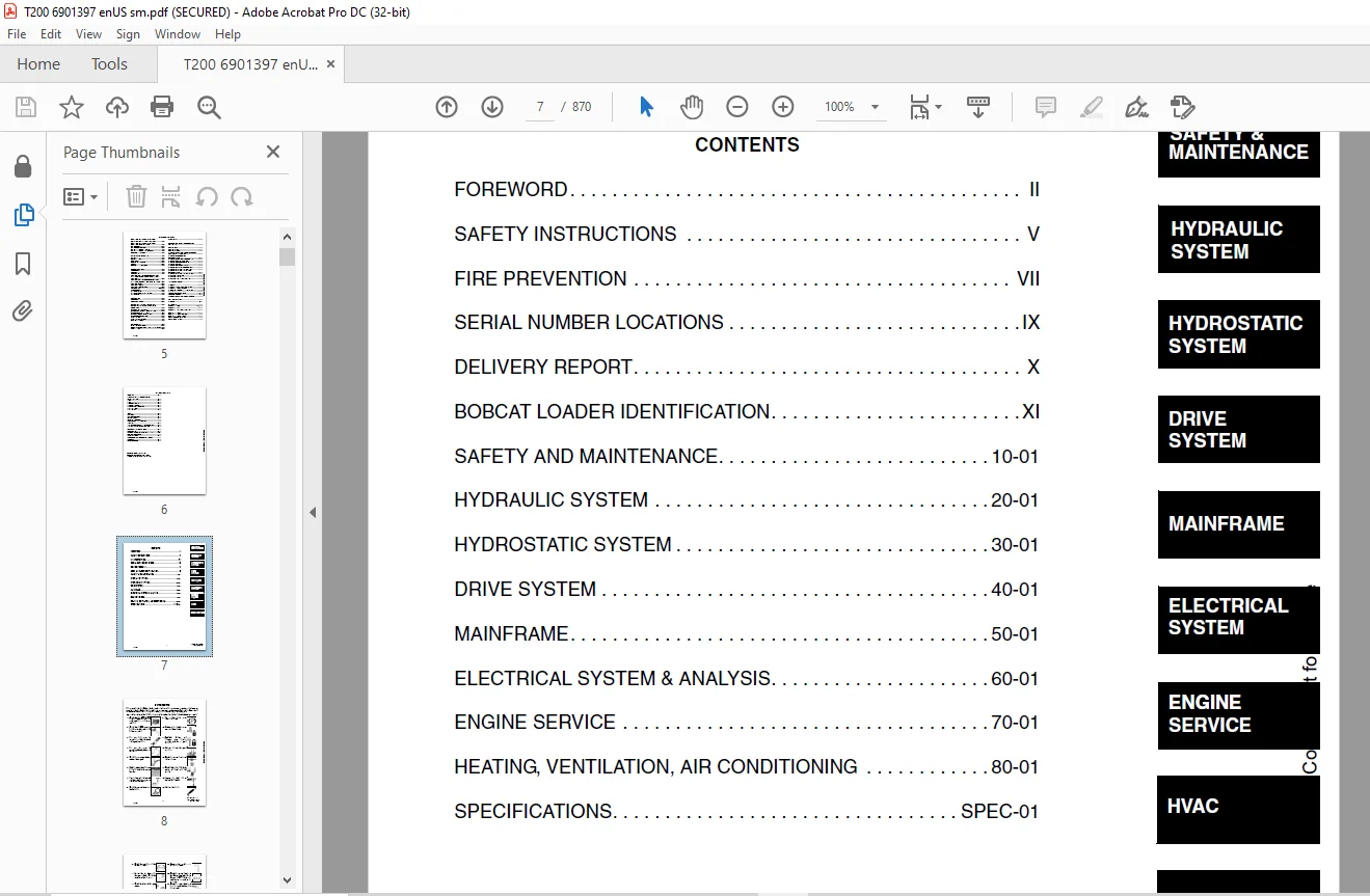
TABLE OF CONTENTS:
Bobcat T200 Turbo T200 Turbo High Flow Loader Service Manual 6901397 (10-12) – PDF DOWNLOAD
MAINTENANCE SAFETY..............................................................................  3
ALPHABETICAL INDEX..............................................................................  5
CONTENTS........................................................................................  7
	FOREWORD....................................................................................  8
	SAFETY INSTRUCTIONS......................................................................... 11
	FIRE PREVENTION............................................................................. 13
		Maintenance............................................................................. 13
		Operation............................................................................... 13
		Electrical.............................................................................. 13
		Hydraulic System........................................................................ 13
		Fueling................................................................................. 13
		Starting................................................................................ 13
		Spark Arrestor Exhaust System........................................................... 13
		Welding And Grinding.................................................................... 14
		Fire Extinguishers...................................................................... 14
	SERIAL NUMBER LOCATIONS..................................................................... 15
		Loader Serial Number.................................................................... 15
		Engine Serial Number.................................................................... 15
	DELIVERY REPORT............................................................................. 16
	BOBCAT LOADER IDENTIFICATION................................................................ 17
SAFETY AND MAINTENANCE.......................................................................... 19
	LIFTING AND BLOCKING THE LOADER............................................................. 21
		Procedure............................................................................... 21
	LIFT ARM SUPPORT DEVICE..................................................................... 23
		Engaging The Lift Arm Support Device.................................................... 23
		Disengaging The Lift Arm Support Device................................................. 25
	OPERATOR CAB................................................................................ 27
		Raising The Operator Cab................................................................ 27
		Lowering the Operator Cab............................................................... 28
		Emergency Exit.......................................................................... 29
	TRANSPORTING THE BOBCAT LOADER.............................................................. 31
		Procedure............................................................................... 31
		Stopping The Bobcat Loader.............................................................. 31
	TOWING THE LOADER........................................................................... 33
		Procedure (S/N 517515079, 516815098, 518916041 And Below)............................... 33
		Procedure (S/N 517515079, 516815098, 518916041 and Above)............................... 35
	REMOTE START................................................................................ 37
		Procedure For Loader Without Attachments Control Harness................................ 37
		Procedure For Loader With Attachments Control Harness................................... 38
		Procedure............................................................................... 40
	SERVICE SCHEDULE............................................................................ 41
		Chart................................................................................... 41
	AIR CLEANER SERVICE......................................................................... 43
		Replacing Filter Element................................................................ 43
	ENGINE COOLING SYSTEM....................................................................... 45
		Cleaning The Cooling System............................................................. 45
	FUEL SYSTEM................................................................................. 47
		Fuel Specifications..................................................................... 47
		Filling the Fuel Tank................................................................... 47
		Fuel Filter............................................................................. 48
		Fuel Lift Pump Strainer................................................................. 49
		Removing Air From The Fuel System....................................................... 49
	ENGINE LUBRICATION SYSTEM................................................................... 51
		Checking Engine Oil..................................................................... 51
		Replacing Oil And Filter................................................................ 52
	HYDRAULIC / HYDROSTATIC SYSTEM.............................................................. 53
		Checking And Adding Fluid............................................................... 53
		Hydraulic / Hydrostatic Filter Replacement.............................................. 53
		Replacing Hydraulic Fluid (518911353 & Below)........................................... 54
		Replacing Hydraulic Fluid (518911354 & Above)........................................... 56
	FAN GEARBOX................................................................................. 57
		Checking And Adding Oil................................................................. 57
	BOB-TACH.................................................................................... 59
		Inspection And Maintenance.............................................................. 59
	POWER BOB-TACH (OPTION)..................................................................... 61
		Inspection And Maintenance.............................................................. 61
	LUBRICATING THE LOADER...................................................................... 63
		Procedure............................................................................... 63
HYDRAULIC SYSTEM................................................................................ 65
	HYDRAULIC / HYDROSTATIC SCHEMATICS.......................................................... 71
	HYDRAULIC SYSTEM INFORMATION................................................................ 87
		Glossary Of Hydraulic / Hydrostatic Symbols For Loaders................................. 87
		Troubleshooting......................................................................... 91
		Tighten Procedures...................................................................... 92
	CYLINDER (LIFT)............................................................................. 93
		Checking................................................................................ 93
		Removal And Installation................................................................ 93
		Parts Identification.................................................................... 95
		Disassembly............................................................................. 96
		Assembly................................................................................ 97
	CYLINDER (TILT).............................................................................101
		Checking................................................................................101
		Removal And Installation................................................................101
		Rod End Seal............................................................................102
		Parts Identification....................................................................104
		Disassembly.............................................................................105
		Assembly................................................................................107
	CYLINDER (POWER BOB-TACH)...................................................................111
		Checking................................................................................111
		Removal And Installation................................................................112
		Parts Identification....................................................................113
		Disassembly.............................................................................114
		Assembly................................................................................115
	MAIN RELIEF VALVE...........................................................................119
		Checking The Main Relief Valve At Front Auxiliary Hydraulics............................119
		Removal And Installation................................................................120
		Adjustment..............................................................................121
	HYDRAULIC CONTROL VALVE (FOOT CONTROL)......................................................123
		Removal And Installation (S/N 518915181 & Below)........................................123
		Removal And Installation (S/N 518915182 & Above)........................................130
		BICS™ Valve, Removal And Installation...................................................135
		BICS™ Valve, Lift Arm Bypass Orifice Disassembly And Assembly...........................136
		BICS™ Valve, Check Valve Disassembly And Assembly (S/N 518916163 & Below)...............137
		BICS™ Valve, Check Valve Disassembly And Assembly (S/N 518916164 & Above)...............138
		BICS™ Valve, Lock Valve Disassembly And Assembly........................................139
		BICS™ Valve, Solenoid Disassembly And Assembly..........................................140
		BICS™ Valve, Solenoid Testing...........................................................141
		Identification Chart....................................................................142
		Load Check Valve........................................................................143
		Main Relief Valve.......................................................................144
		Port Relief Valve, Tilt Spool (Linkage End).............................................144
		Port Relief Valve, Lift Spool (Bonnet End)..............................................145
		Anti-Cavitation Valve / Port Relief Valve, Tilt Spool (Bonnet End)......................145
		Anti-Cavitation Valve, Lift Spool (Linkage End).........................................146
		Rubber Boot.............................................................................146
		Lift And Tilt Lock Block................................................................147
		Lift Spool and Detent...................................................................148
		Tilt Spool Removal And Installation.....................................................156
		Auxiliary Spool Removal And Installation (Bonnet End)...................................158
		Auxiliary Spool Removal And Installation (Linkage End)..................................159
		Auxiliary Plug Removal And Installation.................................................160
		Auxiliary Electric Solenoid Disassembly.................................................161
		Port Relief-Auxiliary Section Disassembly...............................................162
		Cleaning And Inspection.................................................................162
	HYDRAULIC CONTROL VALVE (ADVANCED CONTROL SYSTEM) (ACS).....................................163
		Actuator Removal And Installation (In Loader) (S/N 518915181 & Below)...................163
		Removal And Installation (S/N 518915181 & Below)........................................165
		Actuator Removal And Installation (In Loader) (S/N 518915182 & Above)...................171
		Actuator Removal And Installation (Out Of Loader).......................................173
		Removal And Installation (S/N 518915182 & Above)........................................174
		BICS™ Valve, Removal And Installation...................................................179
		BICS™ Valve, Lift Arm Bypass Orifice Disassembly And Assembly...........................181
		BICS™ Valve, Check Valve Disassembly And Assembly.......................................182
		BICS™ Valve, Lock Valve Disassembly And Assembly........................................183
		BICS™ Valve, Solenoid Disassembly And Assembly..........................................184
		BICS™ Valve, Solenoid Testing...........................................................185
		Identification Chart....................................................................186
		Identification Chart....................................................................187
		Lift Base End Restrictor................................................................188
		Load Check Valve........................................................................188
		Main Relief Valve.......................................................................189
		Port Relief Valve.......................................................................190
		Anti-Cavitation Valve / Port Relief Valve...............................................191
		Anti-Cavitation Valve...................................................................192
		Lift Spool Removal......................................................................193
		Lift Spool Removal And Installation.....................................................194
		Lift and Tilt Spool Disassembly And Assembly............................................195
		Auxiliary Spool Removal And Installation................................................196
		Auxiliary Electric Solenoid Disassembly.................................................197
		Port-Auxiliary Section Disassembly......................................................198
		Cleaning And Inspection.................................................................198
	LIFT ARM BYPASS CONTROL VALVE...............................................................199
		Inspecting..............................................................................199
		Additional Inspection For Loaders With Hand Controls....................................199
		Removal And Installation................................................................199
		Disassembly And Assembly................................................................201
	HYDRAULIC PUMP (ALUMINUM)...................................................................203
		Checking The Output Of The Pump (518916260 & Below).....................................203
		Removal And Installation (518916260 & Below)............................................204
		Parts Identification (518916260 & Below)................................................206
		Disassembly (518916260 & Below).........................................................207
		Inspection (518916260 & Below)..........................................................209
		Assembly (518916260 & Below)............................................................210
	HYDRAULIC PUMP (ALUMINUM HI-FLOW)...........................................................213
		Checking The Output Of The High Flow Pump (518916427 & Below)...........................213
	HYDRAULIC PUMP (ALUMINUM HI-FLOW)...........................................................214
		Checking The Output Of The High Flow Pump (518916427 & Below)...........................214
		Removal And Installation (518916427 & Below)............................................215
		Parts Identification (518916427 & Below)................................................217
		Disassembly (518916427 & Below).........................................................218
		Inspection (518916427 & Below)..........................................................222
		Assembly (518916427 & Below)............................................................224
	HYDRAULIC PUMP (CAST IRON)..................................................................227
		Check Output of the Cast Iron Hydraulic Pump (518916261 & Above)........................227
		Removal And Installation (518916261 & Above)............................................229
	HYDRAULIC PUMP (CAST IRON)..................................................................231
		Disassembly And Assembly (518916261 & Above)............................................231
	HYDRAULIC PUMP (CAST IRON HI-FLOW)..........................................................237
		Hydraulic Pump Test (518916428 & Above).................................................237
		Inline Hydraulic Pump Test (518916428 & Above) (Standard)...............................238
		Inline Hydraulic Pump Test (518916428 & Above) (HI- FLOW)...............................240
		High Flow Relief Adjustment Procedure (518916428 & Above)...............................242
		High Flow Relief Valve Removal and Installation (518916428 & Above).....................244
		Removal And Installation (518916428 & Above)............................................246
		Identification (518916428 & Above)......................................................248
		Disassembly And Assembly (518916428 & Above)............................................249
	HYDRAULIC / HYDROSTATIC FILTER..............................................................259
		Housing Removal And Installation (S/N 518913532 & Below)................................259
		Mount Removal And Installation..........................................................260
		Housing Removal And Installation (S/N 518913533 & Above)................................261
	HYDRAULIC FLUID RESERVOIR...................................................................263
		Draining The Hydraulic Fluid Reservoir..................................................263
		Removal And Installation................................................................263
		Hydraulic Fluid Screen..................................................................265
	BUCKET POSITION VALVE.......................................................................267
		Solenoid Removal And Installation.......................................................267
		Solenoid Testing........................................................................267
		Removal And Installation................................................................268
		Disassembly And Assembly................................................................269
	SELECT VALVE................................................................................271
		Checking The High Flow Pump Relief Valve (518916427 & Below)............................271
		Removal And Installation (518916427 & Below)............................................273
		Disassembly And Assembly (518916427 & Below)............................................275
		Solenoid Testing (518916427 & Below)....................................................280
	REAR AUXILIARY DIVERTER VALVE...............................................................281
		Disassembly.............................................................................281
		Inspection..............................................................................281
		Solenoid Testing........................................................................282
		Assembly................................................................................282
	POWER BOB-TACH BLOCK........................................................................283
		Removal And Installation................................................................283
		Disassembly And Assembly................................................................285
	AUXILIARY PRESSURE RELEASE (ACCUMULATOR)....................................................291
		Removal and Installation (518916010 & Below)............................................291
		Disassembly And Assembly (518916010 & Below)............................................292
	FRONT AUXILIARY HYDRAULIC COUPLER BLOCK.....................................................293
		Removal And Installation (518916011 & Above)............................................293
		Disassembly And Assembly (518916011 & Above)............................................293
HYDROSTATIC SYSTEM..............................................................................295
	HYDROSTATIC SYSTEM INFORMATION..............................................................297
		Troubleshooting Chart...................................................................297
		Replenishing Valve Function.............................................................298
	HYDROSTATIC MOTOR...........................................................................299
		Removal And Installation................................................................299
		Parts Identification....................................................................301
		Disassembly.............................................................................303
		Inspection..............................................................................311
		Assembly................................................................................312
		Filling.................................................................................320
	CHARGE PRESSURE SENDER......................................................................323
		Removal and Installation................................................................323
		Checking Charge Pressure................................................................324
	HYDROSTATIC PUMP............................................................................325
		Removal And Installation................................................................325
		Replenishing / High Pressure Relief Valve(s)............................................327
		Parts Identification (Right Half).......................................................328
		Parts Identification (Left Half)........................................................330
		Hydraulic Pump Removal And Installation.................................................332
		Disassembly.............................................................................333
		Assembly................................................................................341
	DRIVE BELT..................................................................................349
		Shield Removal And Installation.........................................................349
		Adjustment..............................................................................350
		Replacement.............................................................................350
		Tensioner Pulley Removal And Installation...............................................351
		Tensioner Pulley Disassembly And Assembly...............................................352
		Tensioner Pulley Tension Spring.........................................................353
	OIL COOLER..................................................................................355
		Removal and Installation................................................................355
		Removal And Installation With STC (Seal Tight Connector)................................356
DRIVE SYSTEM....................................................................................357
	BRAKE (S/N 518916041 AND BELOW).............................................................359
		Switch Operated Parking Brake...........................................................359
		Block Removal And Installation..........................................................359
		Block Disassembly And Assembly..........................................................362
		Traction Lock Bypass Knob...............................................................362
	BRAKE (S/N 518916042 AND ABOVE).............................................................363
		Switch Operated Parking Brake...........................................................363
		Block Removal And Installation..........................................................363
		Block Disassembly And Assembly..........................................................365
	DRIVE COMPONENTS............................................................................367
		Track Checking..........................................................................367
		Track Adjustment........................................................................368
		Track Removal And Installation..........................................................369
		Track Idler (Front) End Play Specifications.............................................372
		Track Idler (Front) Removal And Installation............................................372
		Track Idler (Front) Parts Identification (S/N 518916540 & Below)........................375
		Track Idler (Front) Disassembly (S/N 518916540 & Below).................................376
		Track Idler (Front) Assembly (S/N 518916540 & Below)....................................377
		Track Idler (Rear) End Play Specifications (S/N 518916540 & Below)......................380
		Track Idler (Rear) Removal And Installation (S/N 518916540 & Below).....................380
		Track Idler (Rear) Parts Identification.................................................380
		Track Idler (Rear) Disassembly (S/N 518916540 & Below)..................................381
		Track Idler (Rear) Assembly (S/N 518916540 & Below).....................................382
		Track Roller Assembly End Play Specifications (S/N 518916540 & Below)...................384
		Track Roller Parts Identification.......................................................384
		Track Roller Removal And Installation (S/N 518916540 & Below)...........................384
		Track Roller Disassembly (S/N 518916540 & Below)........................................385
		Track Roller Assembly...................................................................386
		Track Idler (Front) Parts Identification (S/N 518916541 & Above)........................388
		Track Idler (Front) Disassembly (S/N 518916541 & Above).................................389
		Track Idler (Front) Assembly............................................................390
		Track Idler (Rear) End Play Specifications (S/N 518916541 & Above)......................393
		Track Idler (Rear) Parts Identification.................................................393
		Track Idler (Rear) Removal And Installation.............................................393
		Track Idler (Rear) Disassembly (S/N 518916541 & Above)..................................394
		Track Roller Assembly End Play Specifications (S/N 518916541 & Above)...................397
		Track Roller Parts Identification.......................................................397
		Track Roller Removal And Installation...................................................397
		Track Roller Disassembly (S/N 518916541 & Above)........................................398
		Track Housing Removal And Installation..................................................401
		Track Damage Identification.............................................................402
MAINFRAME.......................................................................................413
	SEAT BAR....................................................................................415
		Removal And Installation................................................................415
		Assembling Components...................................................................416
		Compression Spring Disassembly And Assembly.............................................418
	OPERATOR CAB................................................................................419
		Gas Cylinder Removal And Installation...................................................419
		Gas Cylinder Disassembly And Assembly...................................................420
		Removal And Installation................................................................421
	OPERATOR SEAT...............................................................................423
		Removal And Installation................................................................423
		Seat Belt Removal And Installation......................................................423
	OPERATOR SEAT (SUSPENSION)..................................................................425
		Removal And Installation................................................................425
		Slide Rail Removal And Installation.....................................................426
		Cushion Removal And Installation........................................................426
		Back Removal And Installation...........................................................427
		Shock Removal And Installation..........................................................428
	BOB-TACH....................................................................................429
		Inspection And Maintenance..............................................................429
		Bob-Tach Lever And Wedge................................................................430
		Removal And Installation................................................................432
		Pivot Pin Bushing And Seal Replacement..................................................434
	POWER BOB-TACH..............................................................................435
		Inspection And Maintenance..............................................................435
		Power Bob-Tach Lever And Wedge..........................................................436
		Removal And Installation................................................................437
		Pivot Pin Bushing And Seal Replacement..................................................439
	LIFT ARMS...................................................................................441
		Removal And Installation................................................................441
	REAR GRILL..................................................................................445
		Removal And Installation................................................................445
	REAR DOOR...................................................................................447
		Removal And Installation................................................................447
		Adjusting The Rear Door Latch (S/N 516815093, 517515070, 518915871 & Below.)............448
		Striker Removal And Installation (S/N 516815094, 517515071, 518915872 & Above.).........448
		Adjusting The Striker (S/N 516815094, 517515071, 518915872 & Above.)....................449
		Latch Removal And Installation (S/N 516815094, 517515071, 518915872 & Above.)...........449
	FUEL TANK...................................................................................451
		Removal And Installation................................................................451
		Fuel Level Sender.......................................................................454
		Fuel Pick-up Screen / Check Valve.......................................................454
	CONTROL PEDALS..............................................................................455
		Control Pedal Removal And Installation..................................................455
		Control Pedal Adjustment................................................................455
		Crossbar Linkage Removal And Installation...............................................455
		Crossbar Linkage Inspection.............................................................456
	CONTROL PANEL...............................................................................457
		Removal and Installation................................................................457
	CONTROL PEDALS (ACS)........................................................................459
		Foot Sensor Removal And Installation....................................................459
		Foot Pedal Removal And Installation.....................................................460
		Foot Pedal Linkage Disassembly And Assembly.............................................460
	CONTROL HANDLE..............................................................................461
		Shock Removal And Installation..........................................................461
		Shaft Removal And Installation..........................................................461
		Shaft Disassembly And Assembly..........................................................462
		Lever Removal And Installation..........................................................462
		Rubber Boot Replacement.................................................................463
		Linkage Removal And Installation........................................................464
		Linkage Adjustment......................................................................467
		Linkage Neutral Adjustment..............................................................469
	CONTROL HANDLE (ADVANCED CONTROL SYSTEM) (ACS) advanced hand control........................473
		Components Identification...............................................................473
		Handle Sensor Removal And Installation..................................................473
		Control Handle Removal and Installation.................................................477
		Control Handle Disassembly and Assembly.................................................478
		Control Lever Removal and Installation..................................................478
		Control Lever Boot......................................................................479
	CONTROL HANDLE (ADVANCED CONTROL SYSTEM) (ACS) SELECTABLE HAND / FOOT CONTROL...............481
		Components Identification...............................................................481
		Handle Sensor Removal And Installation..................................................481
		Control Handle Removal and Installation.................................................485
		Control Handle Disassembly and Assembly.................................................486
		Control Lever Removal and Installation..................................................486
		Control Lever Removal and Installation (Cont’d).........................................487
		Control Lever Boot......................................................................487
ELECTRICAL SYSTEM & ANALYSIS....................................................................489
	ELECTRICAL SCHEMATICS.......................................................................493
	ELECTRICAL SYSTEM INFORMATION...............................................................499
		Troubleshooting Chart...................................................................501
		Description.............................................................................502
		Fuse Location...........................................................................504
		Relay Switch Location...................................................................504
		Solenoid Test...........................................................................505
	BATTERY.....................................................................................507
		Removal And Installation................................................................507
		Servicing The Battery...................................................................508
		Using A Booster Battery.................................................................509
	ALTERNATOR (90 AMP).........................................................................511
		Adjusting The Alternator Belt...........................................................511
		Alternator Identification...............................................................511
		Charging System Check...................................................................512
		Alternator Voltage Test.................................................................513
		Low Voltage Test........................................................................513
		High Voltage Test.......................................................................514
		Removal And Installation................................................................515
		Rectifier Continuity (Diode) Test.......................................................516
		Alternator Regulator Test...............................................................517
		Disassembly.............................................................................517
		Stator Continuity Test..................................................................518
		Stator Ground Test......................................................................518
		Rotor Continuity Test...................................................................518
		Rotor Ground Test.......................................................................518
		Assembly................................................................................519
	STARTER (NIPPONDENSO).......................................................................521
		Removal And Installation................................................................521
		Parts Identification....................................................................522
		Disassembly And Assembly................................................................523
		External Pinion.........................................................................526
		Inspection And Repair...................................................................527
		No Load Test............................................................................531
	STARTER (VALEO).............................................................................533
		Checking................................................................................533
		Removal And Installation................................................................534
		Parts Identification....................................................................535
		Disassembly and Assembly................................................................536
		Inspection And Repair...................................................................539
		No Load Test............................................................................541
	INSTRUMENT PANEL............................................................................543
		Left Panel (Standard)...................................................................543
		Right Panel-Standard Instrument Panel (With Key Switch).................................544
		Right Panel (Deluxe) (With Keyless Start)...............................................545
		Right Panel Setup Display Options (Deluxe)..............................................547
		Passwords...............................................................................548
		Option And Field Accessory Panels.......................................................550
		Standard Panel Removal And Installation (Right Side)....................................551
		Deluxe Panel Removal And Installation (Right Side)......................................552
		Standard And Deluxe Panel Removal And Installation (Left Side)..........................553
		Front Accessory Panel Removal And Installation..........................................554
	LIGHTS......................................................................................557
		Front Removal And Installation..........................................................557
		Rear Removal And Installation...........................................................558
	BOBCAT CONTROLLER...........................................................................559
		Identification Chart (S/N 518916788 & Below)............................................559
	BOBCAT CONTROLLER (CONT’D)..................................................................560
		Identification Chart (S/N 518916789 & Above)............................................560
		Removal And Installation................................................................562
	DIAGNOSTICS SERVICE CODES...................................................................565
		Display.................................................................................565
	BICS™ SYSTEM................................................................................567
		Inspecting The BICS™ Controller (Engine STOPPED - Key ON)...............................567
		Inspecting Deactivation Of The Auxiliary Hydraulics System (Engine STOPPED - Key ON)....567
		Inspecting The Seat Bar Sensor (Engine RUNNING).........................................567
		Inspecting The Traction Lock (Engine RUNNING)...........................................567
		Inspecting The Lift Arm Bypass Control..................................................567
		Additional Inspection For Loaders With Advanced Hand Controls...........................568
		Troubleshooting Chart...................................................................569
		Troubleshooting Guide...................................................................570
	SEAT BAR SENSOR.............................................................................571
		Troubleshooting Chart...................................................................571
		Test....................................................................................572
		Removal And Installation................................................................573
		BICS™ Circuit Test......................................................................574
	TRACTION LOCK...............................................................................575
		Troubleshooting Chart...................................................................575
		Description Of The Control System.......................................................576
		Inspecting The Control System...........................................................576
		Parking Brake Solenoid Removal And Installation (S/N 518916040 & Below).................577
		Parking Brake Solenoid Removal And Installation (S/N 518916041 & Above).................578
		Traction Lock Bypass Knob...............................................................579
	ADVANCED CONTROL SYSTEM (ACS) ADVANCED HAND CONTROL.........................................581
		Components Identification...............................................................581
		Troubleshooting Guide...................................................................582
		Controller, Connector And Wire Identification...........................................583
		ACS Controller Removal And Installation.................................................584
		Handle Sensor Connector.................................................................585
		Switch Handle Removal...................................................................586
		Switch Handle Installation..............................................................588
		Actuators Disassembly and Assembly......................................................591
	ADVANCED CONTROL SYSTEM (ACS) SELECTABLE HAND / FOOT CONTROL................................593
		Components Identification...............................................................593
		Troubleshooting Guide...................................................................595
		Controller, Connector And Wire Identification...........................................596
		ACS Controller Removal And Installation.................................................597
		Handle Sensor Connector.................................................................598
		Switch Handle Removal...................................................................599
		Switch Handle Installation..............................................................601
		Actuators Disassembly and Assembly......................................................604
		Handle Lock Solenoid Removal And Installation...........................................605
		Handle Lock Solenoid Disassembly And Assembly...........................................605
		Handle Lock Solenoid Connector..........................................................606
		Calibration Of The ACS System...........................................................607
		Switchable Hand / Foot Controls Calibration Procedure...................................607
		Hand Controls Only Calibration Procedure................................................608
		Foot Sensor Disassembly And Assembly....................................................610
		Foot Sensor Connector...................................................................610
		Foot Lock Solenoid Removal And Installation.............................................611
		Foot Lock Solenoid Connector............................................................611
	ELECTRICAL / HYDRAULIC CONTROLS REFERENCE...................................................613
		Controls Identification Chart...........................................................613
ENGINE SERVICE..................................................................................615
	TROUBLESHOOTING.............................................................................617
		Chart...................................................................................617
	ENGINE SPEED CONTROL........................................................................619
		Removal And Installation................................................................619
		Speed Control Cable.....................................................................620
		Speed Control Linkage...................................................................621
	MUFFLER.....................................................................................623
		Removal And Installation................................................................623
	AIR CLEANER.................................................................................625
		Housing Removal And Installation........................................................625
	RADIATOR....................................................................................627
		Oil Cooler Removal And Installation.....................................................627
	COOLING FAN.................................................................................629
		Drive Tension Pulley Removal And Installation...........................................629
		Gearbox / Blower Housing Removal And Installation.......................................630
		Blower Removal And Installation.........................................................633
		Gearbox Parts Identification............................................................634
		Gearbox Disassembly.....................................................................635
		Gearbox Assembly........................................................................640
		Gearbox, Checking Backlash..............................................................645
	ENGINE COMPONENTS AND TESTS.................................................................649
		Engine Compression, Checking............................................................649
		Glow Plug, Checking.....................................................................650
		Fuel Shut-Off Solenoid, Checking........................................................651
		Fuel Shut-Off Solenoid Removal and Installation.........................................652
		Fuel Injection Pump Removal.............................................................652
		Fuel Injection Pump Timing..............................................................654
		Fuel Injection Pump Installation........................................................655
		Fuel Injector Removal and Installation..................................................657
		Fuel Injector, Checking.................................................................658
		Fuel Injector Disassembly...............................................................659
		Fuel Injector Assembly..................................................................660
		Timing Belt Inspection..................................................................662
		Timing Belt Removal.....................................................................662
		Timing Belt Installation................................................................663
		Timing Belt, Replacement In the Loader..................................................667
		Valve Clearance Adjustment..............................................................672
		Valve Timing, Checking..................................................................673
		Thermostat, Oil Pressure Control Valves And Heater Connections..........................675
	ENGINE AND ENGINE MOUNTS....................................................................679
		Removal And Installation................................................................679
		Engine Mount Replacement................................................................685
	FLYWHEEL AND HOUSING........................................................................687
		Flywheel Removal And Installation.......................................................687
		Ring Gear Removal And Installation......................................................687
		Flywheel Housing Removal And Installation...............................................687
	RPM SENSOR..................................................................................689
		Adjustment..............................................................................689
	RECONDITIONING THE ENGINE...................................................................691
		Deutz Engine Tools Identification Chart.................................................691
		Disassembly.............................................................................692
		Assembly................................................................................696
		Cylinder, Checking......................................................................712
		Camshaft Bearing, Checking..............................................................713
		Camshaft Bearing, Removal And Installation..............................................713
		Control Rod Guide Bushing Removal.......................................................714
		Control Rod Guide Bushing Installation..................................................716
		Rear Cover Seal Removal And Installation................................................720
		Crankshaft, Checking....................................................................721
		Connecting Rod, Checking................................................................723
		Piston, Checking........................................................................725
		Piston Pin, Checking....................................................................726
		Piston Rings Installation...............................................................726
		Piston Installation On the Connecting Rod...............................................727
		Cylinder Head Disassembly...............................................................729
		Valves, Checking........................................................................729
		Valve Seats, Checking...................................................................730
		Valve Spring, Checking..................................................................731
		Cylinder Head Assembly..................................................................731
		Rocker Arm and Bracket, Checking........................................................732
		Front Cover Disassembly.................................................................733
		Front Cover Assembly....................................................................738
		Turbo Charger Removal and Installation..................................................747
		Crankshaft Gear Mounting Bolt Torque Procedure..........................................748
HEATING, VENTILATION, AIR CONDITIONING..........................................................751
	AIR CONDITIONING SYSTEM FLOW................................................................754
		Principals..............................................................................754
		Chart...................................................................................755
	COMPONENTS..................................................................................757
		Identification..........................................................................757
	SAFETY......................................................................................761
		Safety Equipment........................................................................761
	REGULAR MAINTENANCE.........................................................................763
		Filter Elements Removal And Installation................................................763
		Compressor Drive Belt Inspection........................................................764
		Cleaning The Condenser..................................................................764
	BASIC TROUBLESHOOTING.......................................................................767
		Poor A/C Performance....................................................................767
		Cleaning The A/C Evaporator Coil & Heater Coil..........................................767
		Receiver / Drier Sight Glass Inspection.................................................770
		Compressor Drive Belt Inspection:.......................................................771
		Checking The Electrical System..........................................................771
		Engine Coolant Bypassing The Heater Valve...............................................779
		Heater Valve Not Opening Or Closing.....................................................779
	GENERAL AIR CONDITIONING SERVICE GUIDELINES.................................................781
		Compressor Oil..........................................................................781
		Compressor Oil Check....................................................................782
		Component Replacement And Refrigeration Leaks...........................................783
	SYSTEM TROUBLESHOOTING CHART................................................................785
		Gauge Pressure Related Troubleshooting..................................................786
	TEMPERATURE / PRESSURE......................................................................789
		Chart...................................................................................789
	AIR CONDITIONING SERVICE....................................................................791
		Chart...................................................................................791
	SYSTEM CHARGING AND RECLAMATION.............................................................793
		Reclamation Procedure...................................................................793
		Charging Procedure With A Manifold Gauge Set............................................795
		Charging Procedure......................................................................796
	COMPRESSOR..................................................................................799
		Removal And Installation................................................................799
		Compressor Clutch Disassembly...........................................................800
	CONDENSER...................................................................................805
		Removal And Installation................................................................805
	RECEIVER / DRIER............................................................................807
		Removal And Installation................................................................807
	PRESSURE RELIEF VALVE.......................................................................809
		Removal And Installation................................................................809
	PRESSURE SWITCH.............................................................................811
		Removal And Installation................................................................811
	THE EVAPORATOR / HEATER UNIT................................................................813
		Removal And Installation................................................................813
		Disassembly And Assembly................................................................814
	THERMOSTAT..................................................................................815
		Removal And Installation................................................................815
	EXPANSION VALVE.............................................................................817
		Removal And Installation................................................................817
	EVAPORATOR..................................................................................819
		Removal And Installation................................................................819
	HEATER COIL.................................................................................821
		Removal And Installation With A/C.......................................................821
		Removal And Installation Without A/C....................................................822
	HEATER / AC FAN.............................................................................825
		Removal And Installation................................................................825
		Disassembly And Assembly................................................................825
		Wire Connector Removal and Installation.................................................827
	HEATER VALVE................................................................................829
		Removal and Installation................................................................829
		Disassembly And Assembly................................................................830
SPECIFICATIONS..................................................................................833
	LOADER SPECIFICATIONS (T200)................................................................835
		Loader Dimensions.......................................................................835
		Performance.............................................................................836
		Controls................................................................................836
		Engine..................................................................................836
		Hydraulic System........................................................................837
		Electrical..............................................................................837
		Drive System............................................................................838
		Capacities..............................................................................838
		Tracks..................................................................................838
		Ground Pressure.........................................................................838
	ENGINE SPECIFICATIONS.......................................................................839
		General.................................................................................839
		Fuel System.............................................................................839
		Valve and Valve Guide and Seat Insert...................................................840
		Piston and Rings........................................................................841
		Connecting Rod..........................................................................841
		Cylinder Head and Block.................................................................842
		Crankshaft and Main Bearings............................................................842
		Camshaft and Bearings...................................................................842
		Oil Pump................................................................................842
	LOADER TORQUE...............................................................................843
		Specifications..........................................................................843
	TORQUE SPECIFICATIONS FOR BOLTS.............................................................847
		Torque For General SAE Bolts............................................................847
		Torque For General Metric Bolts.........................................................848
	HYDRAULIC CONNECTION SPECIFICATIONS.........................................................849
		O-ring Face Seal Connection.............................................................849
		Straight Thread O-ring Fitting..........................................................849
		Tubelines And Hoses.....................................................................849
		Flare Fitting...........................................................................850
		O-ring Flare Fitting....................................................................851
		Port Seal Fitting.......................................................................853
	HYDRAULIC/HYDROSTATIC FLUID SPECIFICATIONS..................................................855
		Specifications..........................................................................855
	CONVERSIONS.................................................................................857
		Decimal And Millimeter Equivalents......................................................857
		U.S. To Metric Conversion Chart.........................................................857
SMR.............................................................................................859
	T200-1......................................................................................859
	T200-2......................................................................................861
	T200-3......................................................................................863
	T200-4......................................................................................865
	T200-5......................................................................................867
	T200-6......................................................................................869
Questions? Email us: [email protected]
PLEASE NOTE:
- This is the same manual used by the DEALERSHIPS to SERVICE your vehicle.
- The manual can be all yours – Once payment is complete, you will be taken to the download page from where you can download the manual. All in 2-5 minutes time!!
- Need any other service / repair / parts manual, please feel free to contact us at heydownloadss @gmail.com . We may surprise you with a nice offer
S.V