Bobcat T250 Turbo T250 High Flow Loader Service Manual 6902451 (10-12) – PDF DOWNLOAD
$32.95
Bobcat T250 Turbo T250 High Flow Loader Service Manual 6902451 (10-12) – PDF DOWNLOAD
S/N 523111001 & Above
S/N 523011001 & Above
Description
Bobcat T250 Turbo T250 High Flow Loader Service Manual 6902451 (10-12) – PDF DOWNLOAD
FILE DETAILS:
Bobcat T250 Turbo T250 High Flow Loader Service Manual 6902451 (10-12) – PDF DOWNLOAD
Language : English
Pages : 732
Downloadable : Yes
File Type : PDF
DESCRIPTION:
Bobcat T250 Turbo T250 High Flow Loader Service Manual 6902451 (10-12) – PDF DOWNLOAD
S/N 523111001 & Above
S/N 523011001 & Above
FOREWORD:
This manual is for the Bobcat loader mechanic. It provides necessary servicing and adjustment procedures for the Bobcat loader and its component parts and systems. Refer to the Operation & Maintenance Manual for operating instructions, starting procedure, daily checks, etc.
A general inspection of the following items must be made after the loader has had service or repair:
IMAGES PREVIEW OF THE MANUAL:
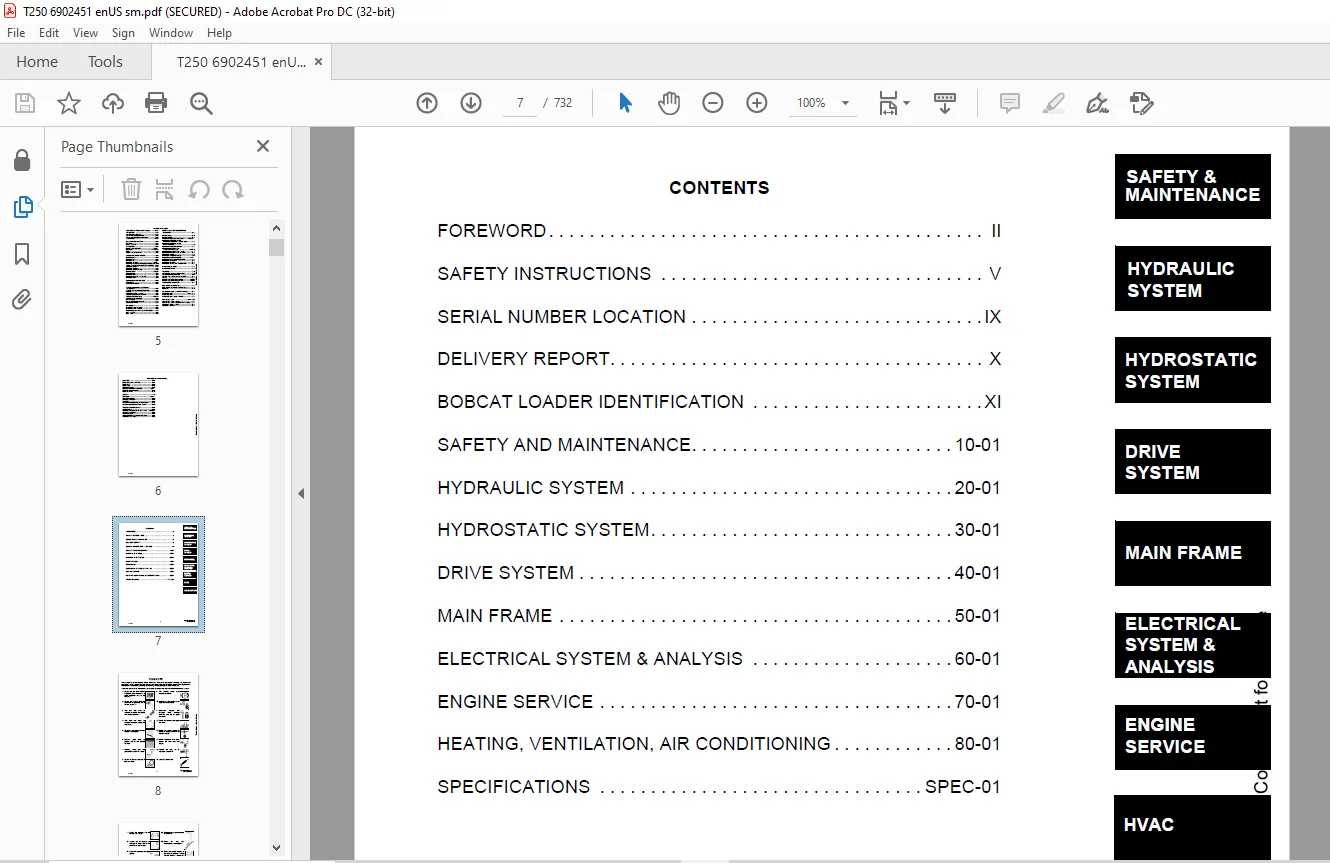
TABLE OF CONTENTS:
Bobcat T250 Turbo T250 High Flow Loader Service Manual 6902451 (10-12) – PDF DOWNLOAD
MAINTENANCE SAFETY....................................................................................................  3
ALPHABETICAL INDEX....................................................................................................  5
CONTENTS..............................................................................................................  7
	FOREWORD..........................................................................................................  8
	SAFETY INSTRUCTIONS............................................................................................... 11
		Fire Prevention............................................................................................... 13
	SERIAL NUMBER LOCATION............................................................................................ 15
		Loader Serial Number.......................................................................................... 15
		Engine Serial Number.......................................................................................... 15
	DELIVERY REPORT................................................................................................... 16
	BOBCAT LOADER IDENTIFICATION...................................................................................... 17
SAFETY AND MAINTENANCE................................................................................................ 19
	LIFTING AND BLOCKING THE LOADER................................................................................... 21
		Procedure..................................................................................................... 21
	LIFT ARM SUPPORT DEVICE........................................................................................... 23
		Engaging The Lift Arm Support Device.......................................................................... 23
		Disengaging The Lift Arm Support Device....................................................................... 24
	OPERATOR CAB...................................................................................................... 25
		Description................................................................................................... 25
		Raising The Operator Cab...................................................................................... 25
		Lowering The Operator Cab..................................................................................... 26
		Emergency Exit................................................................................................ 26
	TRANSPORTING THE BOBCAT LOADER.................................................................................... 29
		Procedure..................................................................................................... 29
	REMOTE START...................................................................................................... 31
		Procedure For Loader W/O Attachments Control Harness.......................................................... 31
		Procedure For Loader With Attachments Control Harness......................................................... 32
		Procedure..................................................................................................... 33
	SERVICE SCHEDULE.................................................................................................. 35
		Chart......................................................................................................... 35
	AIR CLEANER SERVICE............................................................................................... 37
		Replacing Filter Element...................................................................................... 37
	ENGINE COOLING SYSTEM............................................................................................. 39
		Cleaning Cooling System....................................................................................... 39
	FUEL SYSTEM....................................................................................................... 41
		Fuel Specifications........................................................................................... 41
		Filling The Fuel Tank......................................................................................... 41
		Fuel Filter................................................................................................... 42
		Removing Air From The Fuel System............................................................................. 42
	ENGINE LUBRICATION SYSTEM......................................................................................... 43
		Checking Engine Oil........................................................................................... 43
		Oil Chart..................................................................................................... 43
		Replacing Oil And Filter...................................................................................... 43
	HYDRAULIC/HYDROSTATIC SYSTEM...................................................................................... 45
		Checking And Adding Fluid..................................................................................... 45
		Hydraulic/Hydrostatic Filter Replacement...................................................................... 45
		Replacing Hydraulic Fluid And Case Drain Filters.............................................................. 46
	FAN GEARBOX....................................................................................................... 49
		Checking And Adding Oil....................................................................................... 49
	BOB-TACH.......................................................................................................... 51
		Inspection And Maintenance.................................................................................... 51
	POWER BOB-TACH.................................................................................................... 53
		Inspection And Maintenance.................................................................................... 53
	LUBRICATING THE LOADER............................................................................................ 55
		Procedure..................................................................................................... 55
HYDRAULIC SYSTEM...................................................................................................... 57
	HYDRAULIC/HYDROSTATIC SCHEMATICS.................................................................................. 61
	HYDRAULIC SYSTEM INFORMATION...................................................................................... 65
		Troubleshooting............................................................................................... 69
		Tightening Procedure.......................................................................................... 70
	CYLINDER (LIFT)................................................................................................... 71
		Checking...................................................................................................... 71
		Removal And Installation...................................................................................... 71
		Parts Identification.......................................................................................... 73
		Disassembly................................................................................................... 74
		Assembly...................................................................................................... 75
	CYLINDER (TILT)................................................................................................... 79
		Checking...................................................................................................... 79
		Removal And Installation...................................................................................... 79
		Base Pin Removal And Installation............................................................................. 81
		Parts Identification.......................................................................................... 82
		Disassembly................................................................................................... 83
		Assembly...................................................................................................... 84
	CYLINDER (POWER BOB-TACH)......................................................................................... 87
		Checking...................................................................................................... 87
		Removal And Installation...................................................................................... 88
		Parts Identification.......................................................................................... 89
		Disassembly................................................................................................... 90
		Assembly...................................................................................................... 91
	MAIN RELIEF VALVE (FOOT CONTROL).................................................................................. 95
		Checking The Main Relief Valve At Front Aux. Hyd.............................................................. 95
		Removal And Installation...................................................................................... 96
		Adjustment.................................................................................................... 96
	MAIN RELIEF VALVE (ACS)........................................................................................... 97
		Checking The Main Relief Valve At Front Aux. Hyd.............................................................. 97
		Removal And Installation...................................................................................... 98
		Adjustment.................................................................................................... 99
	HYDRAULIC CONTROL VALVE (FOOT CONTROL)............................................................................101
		Removal And Installation......................................................................................101
		BICS™ Valve, Removal And Installation.........................................................................105
		BICS™ Valve, Lift Arm By-Pass Orifice Removal And Installation................................................106
		BICS™ Valve, Check Valve Removal And Installation.............................................................107
		BICS™ Valve, Lock Valve Removal And Installation..............................................................108
		BICS™ Valve, Solenoid Removal And Installation................................................................109
		BICS™ Valve, Solenoid Testing.................................................................................110
		Identification Chart..........................................................................................111
		Load Check Valve..............................................................................................111
		Main Relief Valve.............................................................................................112
		Port Relief Valve, Tilt Spool.................................................................................113
		Port Relief Valve, Lift Spool.................................................................................113
		Anti-Cavitation Valve/Port Relief Valve, Tilt Spool...........................................................114
		Anti-Cavitation Valve, Lift Spool.............................................................................114
		Rubber Boot...................................................................................................115
		Lift And Tilt Lock Block......................................................................................115
		Lift Spool And Detent Removal.................................................................................116
		Tilt Spool Removal And Installation...........................................................................125
		Auxiliary Spool Removal And Installation......................................................................127
		Auxiliary Plug Removal And Installation.......................................................................129
		Auxiliary Electric Solenoid Disassembly.......................................................................130
		Port-Auxiliary Section Removal And Installation...............................................................131
		Cleaning And Inspection.......................................................................................132
	HYDRAULIC CONTROL VALVE (ADVANCED CONTROL SYSTEM) (ACS)...........................................................133
		Actuator Removal And Installation (In Loader).................................................................133
		Actuator Removal And Installation (Out Of Loader).............................................................136
		Removal And Installation......................................................................................137
		BICS™ Valve, Removal And Installation.........................................................................141
		BICS™ Valve, Lift Arm By-Pass Orifice Disassembly And Assembly................................................143
		BICS™ Valve, Check Valve Disassembly And Assembly.............................................................144
		BICS™ Valve, Lock Valve Disassembly And Assembly..............................................................145
		BICS™ Valve, Solenoid Disassembly And Assembly................................................................146
		BICS™ Valve, Solenoid Testing.................................................................................147
		Identification Chart..........................................................................................148
		Lift Base End Restrictor......................................................................................149
		Load Check Valve..............................................................................................149
		Main Relief Valve.............................................................................................150
		Port Relief Valve.............................................................................................151
		Anti-Cavitation Valve/Port Relief Valve.......................................................................152
		Anti-Cavitation Valve.........................................................................................153
		Lift Spool Removal............................................................................................154
		Lift Spool Removal And Installation...........................................................................155
		Lift and Tilt Spool Disassembly And Assembly..................................................................156
		Auxiliary Spool Removal And Installation......................................................................157
		Auxiliary Electric Solenoid Disassembly.......................................................................158
		Port-Auxiliary Section Disassembly............................................................................159
		Cleaning And Inspection.......................................................................................159
	LIFT ARM BY-PASS CONTROL VALVE....................................................................................161
		Inspecting....................................................................................................161
		Additional Inspection For Loaders W/Advanced Hand Controls....................................................161
		Removal And Installation......................................................................................161
		Disassembly And Assembly......................................................................................162
	HYDRAULIC PUMP....................................................................................................163
		Check The Output Of The Hydraulic Pump........................................................................163
		Removal And Installation......................................................................................164
		Identification................................................................................................166
		Disassembly And Assembly......................................................................................167
	HYDRAULIC PUMP (CHARGE)...........................................................................................175
		Check The Output Of The Hydraulic Pump........................................................................175
		Removal and Installation......................................................................................178
		Disassembly and Assembly......................................................................................178
	HYDRAULIC PUMP (HI FLOW)..........................................................................................179
		Hydraulic Pump Test...........................................................................................179
		Inline Hydraulic Pump Test (Standard).........................................................................180
		Inline Hydraulic Pump Test (High Flow)........................................................................182
		High Flow Relief Adjustment Procedure.........................................................................184
		High Flow Relief Valve Removal and Installation...............................................................186
		Removal And Installation......................................................................................188
		Identification................................................................................................190
		Disassembly And Assembly......................................................................................191
	HYDRAULIC/HYDROSTATIC FILTER......................................................................................205
		Housing Removal And Installation..............................................................................205
		Mount Removal And Installation................................................................................206
	HYDRAULIC FLUID RESERVOIR.........................................................................................207
		Fluid Removal.................................................................................................207
		Removal And Installation......................................................................................207
		Hydraulic Fluid Screen........................................................................................210
	BUCKET POSITION VALVE.............................................................................................211
		Solenoid Removal And Installation.............................................................................211
		Solenoid Testing..............................................................................................211
		Removal And Installation......................................................................................212
		Disassembly And Assembly......................................................................................212
	REAR AUXILIARY DIVERTER...........................................................................................215
		Removal and Installation......................................................................................215
		Disassembly And Assembly......................................................................................217
		Solenoid Testing..............................................................................................222
		Inspection....................................................................................................222
	POWER BOB-TACH BLOCK (EARLY MODELS)...............................................................................223
		Removal And Installation......................................................................................223
		Disassembly And Assembly......................................................................................224
	POWER BOB-TACH BLOCK..............................................................................................233
		Removal And Installation......................................................................................233
		Disassembly And Assembly......................................................................................234
	FRONT AUXILIARY HYDRAULIC COUPLER BLOCK...........................................................................239
		Removal and Installation......................................................................................239
		Disassembly And Assembly......................................................................................239
HYDROSTATIC SYSTEM....................................................................................................241
	HYDROSTATIC SYSTEM INFORMATION....................................................................................243
		Troubleshooting Chart.........................................................................................243
		Replenishing Valve Function...................................................................................244
	HYDROSTATIC MOTOR.................................................................................................245
		Removal And Installation......................................................................................245
		Parts Identification..........................................................................................248
		Disassembly...................................................................................................250
		Inspection....................................................................................................258
		Assembly......................................................................................................259
		Filling.......................................................................................................267
	CHARGE PRESSURE SENDER............................................................................................269
		Testing.......................................................................................................269
		Removal and Installation......................................................................................270
		Setting Charge Pressure.......................................................................................271
	HYDROSTATIC PUMP..................................................................................................273
		Removal And Installation......................................................................................273
		Replenishing/High Pressure Relief Valve.......................................................................275
		Parts Identification (Right Half).............................................................................276
		Parts Identification (Left Half)..............................................................................278
		Hydraulic Pump Removal And Installation.......................................................................280
		Pump Separation...............................................................................................280
		Disassembly...................................................................................................281
		Assembly......................................................................................................287
	DRIVE BELT........................................................................................................295
		Shield Removal And Installation...............................................................................295
		Adjustment....................................................................................................295
		Replacement...................................................................................................295
		Tensioner Pulley Removal And Installation.....................................................................296
		Tensioner Pulley Tension Spring...............................................................................298
	OIL COOLER (SEAL TO CONNECT) (STC)................................................................................299
		Hydraulic Oil Cooler Removal and Installation.................................................................299
DRIVE SYSTEM..........................................................................................................301
	BRAKE.............................................................................................................303
		Switch Operated Parking Brake.................................................................................303
		Block Removal And Installation................................................................................303
		Block Disassembly And Assembly................................................................................304
	DRIVE COMPONENTS..................................................................................................305
		Track Checking................................................................................................305
		Track Adjustment..............................................................................................306
		Track Removal And Installation................................................................................307
		Track Idler (Front) End Play Specifications...................................................................309
		Track Idler (Front) Removal And Installation..................................................................309
		Track Idler (Front) Parts Identification......................................................................312
		Track Idler (Front) Disassembly...............................................................................313
		Track Idler (Front) Assembly..................................................................................314
		Track Idler (Rear) End Play Specifications....................................................................317
		Track Idler (Rear) Parts Identification.......................................................................317
		Track Idler (Rear) Removal And Installation...................................................................317
		Track Idler (Rear) Disassembly................................................................................318
		Track Idler (Rear) Assembly...................................................................................320
		Track Roller Assembly End Play Specifications.................................................................321
		Track Roller Parts Identification.............................................................................321
		Track Roller Removal And Installation.........................................................................321
		Track Roller Disassembly......................................................................................322
		Track Roller Assembly.........................................................................................323
		Track Housing Removal And Installation........................................................................325
		Track Damage Identification...................................................................................326
MAIN FRAME............................................................................................................337
	SEAT BAR..........................................................................................................339
		Removal And Installation......................................................................................339
		Assembling Components.........................................................................................340
		Compression Spring Disassembly And Assembly...................................................................341
	OPERATOR CAB......................................................................................................343
		Gas Cylinder Removal And Installation (Dual Gas Spring).......................................................343
		Gas Cylinder Removal And Installation (3rd Gas Spring)........................................................345
		Gas Cylinder Bracket Disassembly And Assembly.................................................................347
		Removal And Installation......................................................................................347
	OPERATOR SEAT.....................................................................................................351
		Removal And Installation......................................................................................351
		Seat Belt Removal And Installation............................................................................351
	OPERATOR SEAT (SUSPENSION)........................................................................................353
		Removal And Installation......................................................................................353
		Slide Rail Removal And Installation...........................................................................354
		Cushion Removal And Installation..............................................................................354
		Back Removal And Installation.................................................................................355
		Shock Removal And Installation................................................................................356
		3-Point Seat Belt Removal And Installation....................................................................357
	BOB-TACH..........................................................................................................359
		Removal And Installation......................................................................................359
		Bob-Tach Lever And Wedge......................................................................................361
	POWER BOB-TACH....................................................................................................363
		Removal And Installation......................................................................................363
		Power Bob-Tach Lever And Wedge................................................................................365
		Pivot Pin Bushing And Seal Replacement........................................................................367
	LIFT ARMS.........................................................................................................369
		Removal And Installation......................................................................................369
	REAR GRILL........................................................................................................373
		Removal And Installation......................................................................................373
	REAR DOOR.........................................................................................................375
		Removal And Installation......................................................................................375
		Adjusting The Rear Door Latch.................................................................................376
	FUEL TANK.........................................................................................................377
		Removal And Installation......................................................................................377
		Fuel Level Sender.............................................................................................379
	CONTROL PEDALS....................................................................................................381
		Removal And Installation......................................................................................381
		Pedal Adjustment..............................................................................................381
	CONTROL PEDALS (ACS)..............................................................................................383
		Foot Sensor Removal And Installation..........................................................................383
		Foot Pedal Removal And Installation...........................................................................384
		Foot Pedal Linkage Disassembly And Assembly...................................................................384
	CONTROL PANEL.....................................................................................................385
		Removal And Installation......................................................................................385
		Shock Removal And Installation................................................................................387
		Shaft Removal And Installation................................................................................387
		Shaft Disassembly And Assembly................................................................................387
		Linkage Removal And Installation..............................................................................389
		Linkage Neutral Adjustment....................................................................................392
	CONTROL HANDLE....................................................................................................399
		Lever Removal And Installation................................................................................399
		Steering Lever Boot...........................................................................................399
	CONTROL HANDLE (ADVANCED CONTROL SYSTEM) (ACS) SELECTABLE HAND/FOOT CONTROL.......................................401
		Components Identification.....................................................................................401
		Handle Sensor Removal And Installation........................................................................401
		Control Handle Removal And Installation.......................................................................404
		Control Handle Disassembly And Assembly.......................................................................405
		Control Lever Removal And Installation........................................................................406
		Control Lever Boot............................................................................................407
	INSIDE ACCESS PANEL...............................................................................................409
		Removal And Installation (Left)...............................................................................409
		Removal And Installation (Right)..............................................................................409
ELECTRICAL SYSTEM & ANALYSIS..........................................................................................411
	ELECTRICAL SCHEMATICS.............................................................................................415
	ELECTRICAL SYSTEM INFORMATION.....................................................................................421
		Troubleshooting...............................................................................................423
		Description...................................................................................................424
		Fuse Location.................................................................................................426
		Relay Switch Location.........................................................................................426
		Solenoid Test.................................................................................................427
	BATTERY...........................................................................................................429
		Removal And Installation......................................................................................429
		Servicing The Electrical System...............................................................................431
		Using A Booster Battery (Jump Starting).......................................................................432
	ALTERNATOR........................................................................................................433
		Adjusting The Alternator Belt.................................................................................433
		Alternator Identification.....................................................................................433
		Charging System Check.........................................................................................434
		Alternator Voltage Test.......................................................................................435
		Low Voltage Test..............................................................................................435
		High Voltage Test.............................................................................................436
		Removal And Installation......................................................................................436
		Rectifier Continuity (Diode) Test.............................................................................437
		Alternator Regulator Test.....................................................................................438
		Disassembly...................................................................................................439
		Stator Continuity Test........................................................................................439
		Stator Ground Test............................................................................................439
		Rotor Continuity Test.........................................................................................440
		Rotor Ground Test.............................................................................................440
		Assembly......................................................................................................440
	STARTER...........................................................................................................441
		Removal And Installation......................................................................................441
		Parts Identification..........................................................................................442
		Checking......................................................................................................443
		Disassembly And Assembly......................................................................................444
		Inspection And Repair.........................................................................................447
		No Load Test..................................................................................................450
	INSTRUMENT PANEL..................................................................................................451
		Left Panel....................................................................................................451
		Right Panel (Standard) (With Key Switch)......................................................................452
		Right Panel (Deluxe) (With Keyless Start).....................................................................453
		Right Panel Setup Display Options (Deluxe)....................................................................455
		Deluxe Panel Setup............................................................................................456
		Passwords (Deluxe)............................................................................................456
		Option And Field Accessory Panels (If Equipped)...............................................................458
		Standard Panel Removal And Installation (Right Side)..........................................................459
		Deluxe Panel Removal And Installation (Right Side)............................................................460
		Standard & Deluxe Panel Removal And Installation (Left Side)..................................................461
		Front Accessory Panel Removal And Installation................................................................462
	LIGHTS............................................................................................................463
		Front Removal And Installation................................................................................463
		Rear Removal And Installation.................................................................................463
	BOBCAT CONTROLLER.................................................................................................466
		Identification Chart..........................................................................................466
		Removal And Installation......................................................................................468
	DIAGNOSTICS SERVICE CODES.........................................................................................469
		Display.......................................................................................................469
		Number Codes List.............................................................................................470
	BICS™ SYSTEM......................................................................................................475
		Inspecting The BICS™ Controller (Engine STOPPED - Key ON).....................................................475
		Inspecting Deactivation Of The Auxiliary Hydraulics System (Engine STOPPED - Key ON)..........................475
		Inspecting The Seat Bar Sensor (Engine RUNNING)...............................................................475
		Inspecting The Traction Lock (Engine RUNNING).................................................................475
		Inspecting The Lift Arm By-Pass Control.......................................................................476
		Additional Inspection For Loaders With Advanced Controls System (ACS) or Selectable Joystick Control (SJC)....476
		Troubleshooting...............................................................................................477
		Troubleshooting Guide.........................................................................................478
	SEAT BAR SENSOR...................................................................................................479
		Troubleshooting Chart.........................................................................................479
		Test..........................................................................................................480
		Removal And Installation......................................................................................481
		BICS™ Circuit Test............................................................................................482
	TRACTION LOCK.....................................................................................................483
		Troubleshooting Chart.........................................................................................483
		Description Of The Control System.............................................................................484
		Inspecting The Control System.................................................................................484
		Parking Brake Solenoid Removal And Installation...............................................................485
	ADVANCED CONTROL SYSTEM (ACS).....................................................................................487
		Components Identification.....................................................................................487
		Troubleshooting Guide.........................................................................................489
		Controller, Connector And Wire Identification.................................................................490
		ACS Controller Removal And Installation.......................................................................491
		Handle Sensor Connector.......................................................................................492
		Switch Handle Removal.........................................................................................493
		Switch Handle Installation....................................................................................495
		Actuators Disassembly And Assembly............................................................................498
		Handle Lock Solenoid Removal And Installation.................................................................499
		Handle Lock Solenoid Disassembly And Assembly.................................................................499
		Handle Lock Solenoid Connector................................................................................500
		Calibration Of The ACS System.................................................................................500
		Switchable Hand/Foot Controls Calibration Procedure...........................................................501
		Hand Controls Only Calibration Procedure......................................................................502
		Foot Sensor Disassembly And Assembly..........................................................................503
		Foot Sensor Connector.........................................................................................504
		Foot Lock Solenoid Removal And Installation...................................................................504
		Foot Lock Solenoid Connector..................................................................................505
	ELECTRICAL/HYDRAULIC CONTROLS REFERENCE...........................................................................507
		Controls Identification Chart.................................................................................507
	FLYWHEEL RPM SENSOR...............................................................................................509
		Adjustment....................................................................................................509
ENGINE SERVICE........................................................................................................511
	TROUBLESHOOTING...................................................................................................515
		Chart.........................................................................................................515
	ENGINE SPEED CONTROL..............................................................................................517
		Removal And Installation......................................................................................517
		Speed Control Cable...........................................................................................518
	MUFFLER...........................................................................................................521
		Removal And Installation......................................................................................521
	AIR CLEANER.......................................................................................................523
		Housing Removal And Installation..............................................................................523
	RADIATOR..........................................................................................................525
		Removal And Installation......................................................................................525
		Mount Removal.................................................................................................527
	COOLING FAN.......................................................................................................529
		Drive Tension Pulley Removal And Installation.................................................................529
		Gearbox/Blower Housing Removal And Installation...............................................................530
		Gearbox Parts Identification..................................................................................533
		Gearbox Disassembly...........................................................................................534
		Gearbox Assembly..............................................................................................539
		Gearbox, Checking Backlash....................................................................................544
	ENGINE............................................................................................................547
		Removal And Installation......................................................................................547
		Mount Replacement.............................................................................................554
		Removal And Installation Tools................................................................................555
	FLYWHEEL AND HOUSING..............................................................................................557
		Flywheel Removal And Installation.............................................................................557
		Ring Gear Removal And Installation............................................................................557
		Flywheel Housing Removal And Installation.....................................................................557
	RECONDITIONING THE ENGINE.........................................................................................559
		Engine Tools Identification Chart.............................................................................559
		Compression Pressure..........................................................................................563
		Cylinder Head Clearance.......................................................................................563
		Valve Cover And Injector Nozzle Removal And Installation......................................................564
		Rocker Arm And Push Rod Disassembly And Assembly..............................................................566
		Valve Clearance...............................................................................................566
		Cylinder Head And Tappet Disassembly And Assembly.............................................................567
		Selecting Cylinder Head Gasket Disassembly And Assembly.......................................................568
		Valve Disassembly And Assembly................................................................................569
		Engine Timing (TDC)...........................................................................................570
		Injection Pump Assembly Removal...............................................................................571
		Injection Pump Assembly Installation..........................................................................574
		Injection Pump Removal and Installation.......................................................................577
		Injection Pump Timing.........................................................................................579
		Fan Drive Pulley Disassembly And Assembly.....................................................................582
		Water Pump Disassembly And Assembly...........................................................................582
		Gearcase Cover Disassembly And Assembly.......................................................................583
		Idle Gear And Camshaft Disassembly And Assembly...............................................................583
		Gearcase Plate Disassembly And Assembly.......................................................................584
		Oil Pan And Oil Strainer Disassembly And Assembly.............................................................584
		Connecting Rod Cap Disassembly And Assembly...................................................................585
		Piston Disassembly And Assembly...............................................................................586
		Piston Ring And Connecting Rod Disassembly And Assembly.......................................................587
		Bearing Case Cover Disassembly And Assembly...................................................................589
		Flywheel Housing Disassembly And Assembly.....................................................................590
		Crankcase No. 2 Disassembly And Assembly......................................................................590
		Crankcase No. 1 And No. 2 Disassembly And Assembly............................................................591
		Crankshaft Disassembly And Assembly...........................................................................591
		Cylinder Head Surface Flatness................................................................................591
		Cylinder Head Flaw............................................................................................592
		Valve Recessing...............................................................................................592
		Valve Lapping.................................................................................................593
		Clearance Between Valve Stem And Valve Guide..................................................................593
		Replacing Valve Guide.........................................................................................594
		Correcting Valve And Valve Seat...............................................................................594
		Free Length And Tilt Of Valve Spring..........................................................................595
		Valve Spring Setting Load.....................................................................................595
		Oil Clearance Between Rocker Arm Shaft And Bearing............................................................596
		Oil Clearance Between Tappet And Tappet Guide Bore............................................................596
		Timing Gear Backlash..........................................................................................597
		Idler Gear Side Clearance.....................................................................................597
		Camshaft Side Clearance.......................................................................................598
		Camshaft Alignment............................................................................................598
		Cam Height....................................................................................................598
		Oil Clearance Between Idler Gear Shaft And Idler Gearing Bushing..............................................599
		Replacing Idler Gear Bushing..................................................................................600
		Piston Pin Bore I.D...........................................................................................601
		Oil Clearance Between Piston Pin And Small End Bushing........................................................601
		Replacing Small End Bushing...................................................................................602
		Clearance Between Piston Ring And Groove......................................................................602
		Piston Ring Gap...............................................................................................603
		Connecting Rod Alignment......................................................................................603
		Crankshaft Side Clearance.....................................................................................604
		Crankshaft Alignment..........................................................................................605
		Oil Clearance Between Crankpin And Crankpin Bearing...........................................................605
		Oil Clearance Between Crankshaft Journal And Crankshaft Bearing...............................................607
		Replacing Crankshaft Sleeve...................................................................................608
		Cylinder Bore I.D.............................................................................................608
		Correcting Cylinder (Oversize +0.5 mm)........................................................................609
		Engine Oil Pressure...........................................................................................609
		Rotor Lobe Clearance..........................................................................................610
		Clearance Between Outer Rotor And Pump Body...................................................................610
		Thermostat Valve Opening Temperature..........................................................................610
		Radiator Water Leakage........................................................................................611
		Radiator Cap Air Leakage......................................................................................611
		Thermostat Assembly...........................................................................................611
		Intake Air Heater.............................................................................................612
		Checking the Turbo Charger....................................................................................613
		Compressor Side...............................................................................................613
		Wheel Shaft...................................................................................................613
		Axial Clearance...............................................................................................614
		Radial Clearance..............................................................................................614
		Air Cleaner, Intake Pipe, Inlet Pipe And Muffler..............................................................614
		Oil Pipe......................................................................................................615
HEATING, VENTILATION, AIR CONDITIONING................................................................................617
	AIR CONDITIONING SYSTEM FLOW......................................................................................620
		Principals....................................................................................................620
		Chart.........................................................................................................621
	COMPONENTS........................................................................................................623
		Identification................................................................................................623
	SAFETY............................................................................................................627
		Safety Equipment..............................................................................................627
	REGULAR MAINTENANCE...............................................................................................629
		Filter Elements Removal And Installation......................................................................629
		Compressor Drive Belt Inspection..............................................................................630
		Cleaning The Condenser........................................................................................631
	BASIC TROUBLESHOOTING.............................................................................................633
		Poor A/C Performance..........................................................................................633
		Cleaning The A/C Evaporator Coil & Heater Coil................................................................634
		Compressor Drive Belt Inspection..............................................................................634
		Checking The Electrical System................................................................................635
		Engine Coolant By-Passing The Heater Valve....................................................................643
		Heater Valve Not Opening Or Closing...........................................................................644
	GENERAL AIR CONDITIONING SERVICE GUIDELINES.......................................................................645
		Compressor Oil................................................................................................645
		Compressor Oil Check..........................................................................................646
		Component Replacement And Refrigeration Leaks.................................................................647
	SYSTEM TROUBLESHOOTING CHART......................................................................................649
		Gauge Pressure Related Troubleshooting........................................................................650
		Troubleshooting Tree..........................................................................................652
	TEMPERATURE/PRESSURE..............................................................................................657
		Chart.........................................................................................................657
	AIR CONDITIONING SERVICE..........................................................................................659
		Chart.........................................................................................................659
	SYSTEM CHARGING AND RECLAMATION...................................................................................661
		Reclamation Procedure.........................................................................................661
		Charging Procedure With A Manifold Gauge Set..................................................................663
		Charging Procedure............................................................................................664
	COMPRESSOR........................................................................................................667
		Removal And Installation......................................................................................667
		Compressor Clutch Disassembly.................................................................................668
	CONDENSER.........................................................................................................673
		Removal And Installation......................................................................................673
	RECEIVER/DRIER....................................................................................................675
		Removal And Installation......................................................................................675
	PRESSURE RELIEF VALVE.............................................................................................677
		Removal And Installation......................................................................................677
	PRESSURE SWITCH...................................................................................................679
		Removal And Installation......................................................................................679
	EVAPORATOR/HEATER UNIT............................................................................................681
		Removal And Installation......................................................................................681
		Disassembly And Assembly......................................................................................682
	THERMOSTAT........................................................................................................683
		Removal And Installation......................................................................................683
	EXPANSION VALVE...................................................................................................685
		Removal And Installation......................................................................................685
	EVAPORATOR........................................................................................................687
		Removal And Installation......................................................................................687
	HEATER COIL.......................................................................................................689
		Removal And Installation With A/C.............................................................................689
		Removal And Installation Without A/C..........................................................................690
	BLOWER FAN........................................................................................................691
		Removal And Installation......................................................................................691
		Disassembly And Assembly......................................................................................692
		Wire Connector Removal and Installation.......................................................................694
	HEATER VALVE......................................................................................................697
		Removal and Installation......................................................................................697
		Disassembly And Assembly......................................................................................698
SPECIFICATIONS........................................................................................................701
	LOADER SPECIFICATIONS (T250)......................................................................................703
		Machine Dimensions............................................................................................703
		Performance...................................................................................................704
		Controls......................................................................................................704
		Engine........................................................................................................704
		Hydraulic System..............................................................................................705
		Electrical....................................................................................................705
		Drive System..................................................................................................706
		Capacities....................................................................................................706
		Tracks........................................................................................................706
	ENGINE SPECIFICATIONS.............................................................................................707
		General.......................................................................................................707
		Fuel System...................................................................................................707
		Valve And Valve Timing........................................................................................707
		Valve Spring..................................................................................................708
		Piston And Piston Ring........................................................................................708
		Connecting Rod................................................................................................708
		Cylinder Head.................................................................................................709
		Crankshaft....................................................................................................709
		Cylinder Bore.................................................................................................709
		Oil Pump......................................................................................................709
		Rocker Arm....................................................................................................710
		Tappet........................................................................................................710
		Camshaft......................................................................................................710
		Thermostat....................................................................................................710
		Timing Gear...................................................................................................711
		Intake Air Heater.............................................................................................711
	TORQUE SPECIFICATIONS FOR BOLTS...................................................................................713
		Torque For General SAE Bolts..................................................................................713
		Torque For General Metric Bolts...............................................................................714
		Torque For Kubota Metric Engine Bolts.........................................................................715
		Tightening Torques For General Use Screws, Bolts And Nuts.....................................................715
	HYDRAULIC CONNECTION SPECIFICATIONS...............................................................................717
		O-ring Face Seal Connection...................................................................................717
		Straight Thread O-ring Fitting................................................................................718
		Tubelines And Hoses...........................................................................................718
		Flare Fitting.................................................................................................718
		O-ring Flare Fitting..........................................................................................719
		Port Seal Fitting.............................................................................................721
	HYDRAULIC FLUID SPECIFICATIONS....................................................................................723
		Specifications................................................................................................723
	CONVERSIONS.......................................................................................................725
		Decimal And Millimeter Equivalents............................................................................725
SMR...................................................................................................................727
	T250-1............................................................................................................727
	T250-2............................................................................................................729
	T250-3............................................................................................................731
Questions? Email us: [email protected]
PLEASE NOTE:
- This is the SAME exact manual used by your dealers to fix your vehicle.
- The same can be yours in the next 2-3 mins as you will be directed to the download page immediately after paying for the manual.
- Any queries / doubts regarding your purchase, please feel free to contact [email protected]
S.V