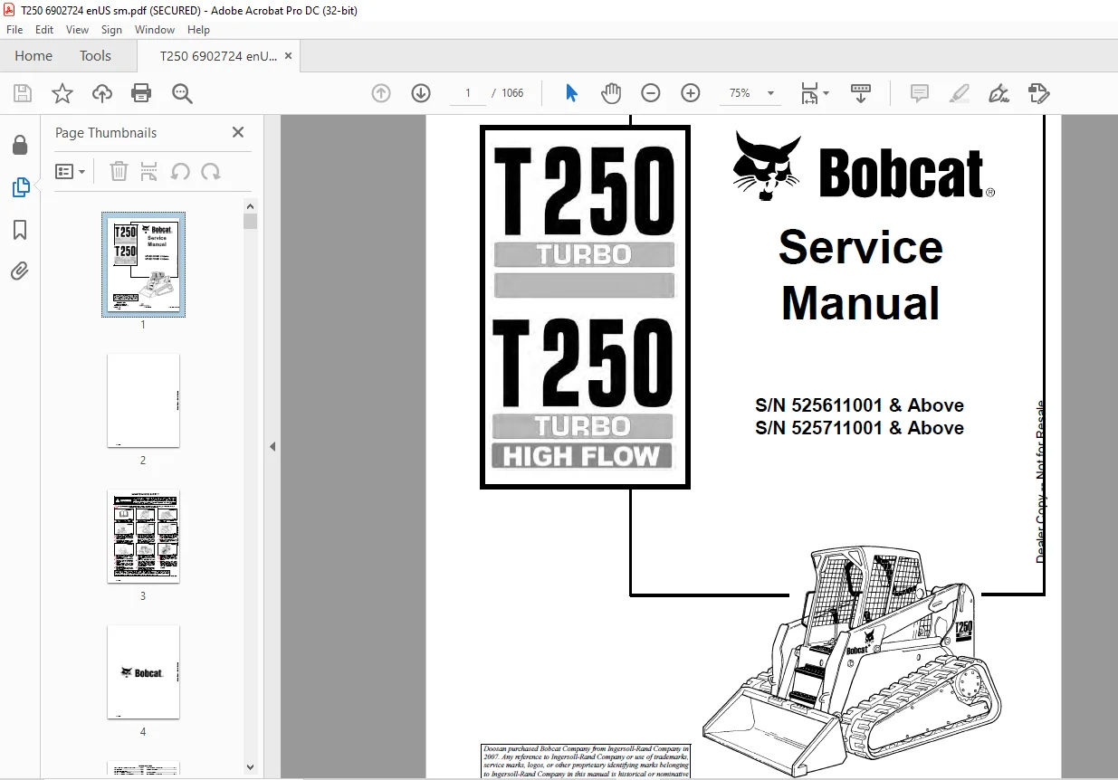
Bobcat T250 Turbo T250 Turbo High Flow Loader Service Manual 6902724 (6-12) – PDF DOWNLOAD
$35.95
Bobcat T250 Turbo T250 Turbo High Flow Loader Service Manual 6902724 (6-12) – PDF DOWNLOAD
S/N 525611001 & Above
S/N 525711001 & Above
Description
Bobcat T250 Turbo T250 Turbo High Flow Loader Service Manual 6902724 (6-12) – PDF DOWNLOAD
FILE DETAILS:
Bobcat T250 Turbo T250 Turbo High Flow Loader Service Manual 6902724 (6-12) – PDF DOWNLOAD
Language : English
Pages : 1066
Downloadable : Yes
File Type : PDF
DESCRIPTION:
Bobcat T250 Turbo T250 Turbo High Flow Loader Service Manual 6902724 (6-12) – PDF DOWNLOAD
S/N 525611001 & Above
S/N 525711001 & Above
FOREWORD:
This manual is for the Bobcat loader mechanic. It provides necessary servicing and adjustment procedures for the Bobcat loader and its component parts and systems. Refer to the Operation & Maintenance Manual for operating instructions, starting procedure, daily checks, etc.
A general inspection of the following items must be made after the loader has had service or repair:
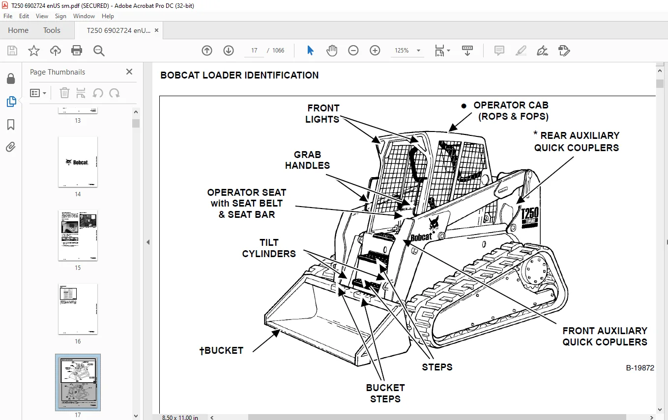
IMAGES PREVIEW OF THE MANUAL:
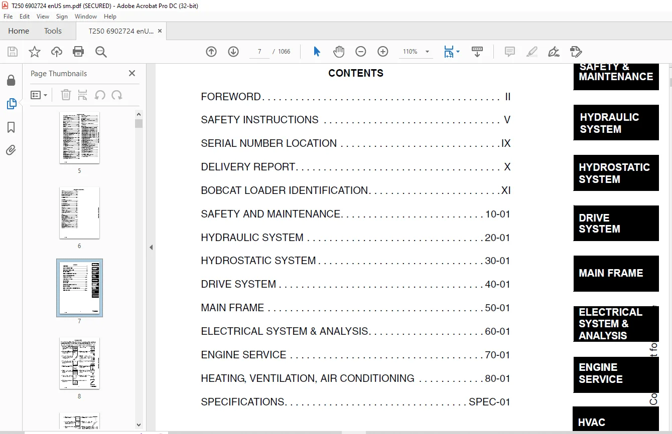
TABLE OF CONTENTS:
Bobcat T250 Turbo T250 Turbo High Flow Loader Service Manual 6902724 (6-12) – PDF DOWNLOAD
MAINTENANCE SAFETY....................................................................................................   3
ALPHABETICAL INDEX....................................................................................................   5
CONTENTS..............................................................................................................   7
	FOREWORD..........................................................................................................   8
	SAFETY INSTRUCTIONS...............................................................................................  11
		Fire Prevention...............................................................................................  13
	SERIAL NUMBER LOCATION............................................................................................  15
		Loader Serial Number..........................................................................................  15
		Engine Serial Number..........................................................................................  15
	DELIVERY REPORT...................................................................................................  16
	BOBCAT LOADER IDENTIFICATION......................................................................................  17
SAFETY AND MAINTENANCE................................................................................................  19
	LIFTING AND BLOCKING THE LOADER...................................................................................  21
		Procedure.....................................................................................................  21
	LIFT ARM SUPPORT DEVICE...........................................................................................  23
		Engaging The Lift Arm Support Device..........................................................................  23
		Disengaging The Lift Arm Support Device.......................................................................  24
	OPERATOR CAB......................................................................................................  25
		Description...................................................................................................  25
		Raising The Operator Cab......................................................................................  25
		Lowering The Operator Cab.....................................................................................  26
		Emergency Exit................................................................................................  26
	TRANSPORTING THE BOBCAT LOADER....................................................................................  29
		Procedure.....................................................................................................  29
	TOWING THE LOADER.................................................................................................  31
		Procedure.....................................................................................................  31
	REMOTE START......................................................................................................  33
		Procedure For Loader W/O Attachments Control Harness..........................................................  33
		Procedure For Loader With Attachments Control Harness.........................................................  34
		Procedure.....................................................................................................  35
	SERVICE SCHEDULE..................................................................................................  37
		Chart.........................................................................................................  37
	AIR CLEANER SERVICE...............................................................................................  39
		Replacing Filter Element......................................................................................  39
	ENGINE COOLING SYSTEM.............................................................................................  41
		Cleaning Cooling System.......................................................................................  41
		Checking The Coolant Level....................................................................................  43
		Adding The Coolant............................................................................................  44
	FUEL SYSTEM.......................................................................................................  45
		Fuel Specifications...........................................................................................  45
		Filling The Fuel Tank.........................................................................................  45
		Fuel Filter...................................................................................................  46
		Removing Air From The Fuel System.............................................................................  46
	ENGINE LUBRICATION SYSTEM.........................................................................................  47
		Checking Engine Oil...........................................................................................  47
		Oil Chart.....................................................................................................  47
		Replacing Oil And Filter......................................................................................  47
	HYDRAULIC/HYDROSTATIC SYSTEM......................................................................................  49
		Checking And Adding Fluid.....................................................................................  49
		Hydraulic Fluid Chart.........................................................................................  49
		Hydraulic/Hydrostatic Filter Replacement......................................................................  50
		Replacing Hydraulic Fluid And Case Drain Filters..............................................................  51
	FAN GEARBOX.......................................................................................................  53
		Checking And Adding Oil.......................................................................................  53
	BOB-TACH..........................................................................................................  55
		Inspection And Maintenance....................................................................................  55
	POWER BOB-TACH....................................................................................................  57
		Inspection And Maintenance....................................................................................  57
	LUBRICATING THE LOADER............................................................................................  59
		Procedure.....................................................................................................  59
HYDRAULIC SYSTEM......................................................................................................  61
	HYDRAULIC/HYDROSTATIC SCHEMATICS..................................................................................  67
	HYDRAULIC SYSTEM INFORMATION......................................................................................  83
		Troubleshooting...............................................................................................  87
		Tightening Procedure..........................................................................................  88
	CYLINDER (LIFT)...................................................................................................  89
		Checking......................................................................................................  89
		Removal And Installation......................................................................................  89
		Parts Identification..........................................................................................  91
		Disassembly...................................................................................................  92
		Assembly......................................................................................................  93
	CYLINDER (TILT)...................................................................................................  97
		Checking......................................................................................................  97
		Removal And Installation......................................................................................  97
		Base Pin Removal And Installation.............................................................................  99
		Parts Identification.......................................................................................... 100
		Disassembly................................................................................................... 101
		Assembly...................................................................................................... 102
	CYLINDER (POWER BOB-TACH)......................................................................................... 105
		Checking...................................................................................................... 105
		Removal And Installation...................................................................................... 106
		Parts Identification.......................................................................................... 107
		Disassembly................................................................................................... 108
		Assembly...................................................................................................... 109
	MAIN RELIEF VALVE................................................................................................. 113
		Checking Main Relief.......................................................................................... 113
		Adjustment.................................................................................................... 115
		Removal And Installation...................................................................................... 116
	HYDRAULIC CONTROL VALVE (2 PIECE CASTING) (FOOT CONTROL).......................................................... 117
		Identification................................................................................................ 117
		Removal And Installation...................................................................................... 117
		BICS™ Valve, Removal And Installation......................................................................... 121
		BICS™ Valve, Lift Arm By-Pass Orifice Removal And Installation................................................ 123
		BICS™ Valve, Check Valve Removal And Installation............................................................. 124
		Backslide, Lock Valve Removal And Installation................................................................ 125
		BICS™ Valve, Solenoid Removal And Installation................................................................ 126
		BICS™ Valve, Solenoid Testing................................................................................. 127
		Identification Chart.......................................................................................... 128
		Load Check Valve.............................................................................................. 129
		Main Relief Valve............................................................................................. 130
		Port Relief Valve, Tilt Spool................................................................................. 130
		Port Relief Valve, Lift Spool................................................................................. 131
		Anti-Cavitation Valve/Port Relief Valve, Tilt Spool........................................................... 131
		Anti-Cavitation Valve, Lift Spool............................................................................. 132
		Rubber Boot................................................................................................... 132
		Lift And Tilt Lock Block...................................................................................... 133
		Lift Spool And Detent Removal................................................................................. 134
		Lift Spool And Detent Disassembly............................................................................. 136
		Lift Spool And Detent Assembly................................................................................ 139
		Lift Spool And Detent Installation............................................................................ 143
		Tilt Spool Removal And Installation........................................................................... 144
		Tilt Spool Disassembly And Assembly........................................................................... 145
		Auxiliary Spool Removal And Installation...................................................................... 146
		Auxiliary Plug Removal And Installation....................................................................... 148
		Auxiliary Electric Solenoid Disassembly....................................................................... 149
		Port-Auxiliary Section Removal And Installation............................................................... 150
		Cleaning And Inspection....................................................................................... 150
	HYDRAULIC CONTROL VALVE (2 PIECE CASTING) (ADVANCED CONTROL SYSTEM) (ACS)......................................... 151
		Identification................................................................................................ 151
		Actuator Removal And Installation (In Loader)................................................................. 152
		Actuator Removal And Installation (Out Of Loader)............................................................. 154
		Removal And Installation...................................................................................... 156
		BICS™ Valve, Removal And Installation......................................................................... 160
		BICS™ Valve, Lift Arm By-Pass Orifice Disassembly And Assembly................................................ 163
		BICS™ Valve, Check Valve Disassembly And Assembly............................................................. 164
		BICS™ Valve, Lock Valve Disassembly And Assembly.............................................................. 165
		BICS™ Valve, Solenoid Disassembly And Assembly................................................................ 166
		BICS™ Valve, Solenoid Testing................................................................................. 167
		Identification Chart.......................................................................................... 168
		Lift Base End Restrictor...................................................................................... 169
		Load Check Valve.............................................................................................. 170
		Main Relief Valve............................................................................................. 171
		Port Relief Valve............................................................................................. 173
		Anti-Cavitation Valve/Port Relief Valve....................................................................... 174
		Anti-Cavitation Valve......................................................................................... 175
		Lift Spool Removal............................................................................................ 176
		Lift Spool Removal And Installation........................................................................... 177
		Lift And Tilt Spool Disassembly And Assembly.................................................................. 178
		Auxiliary Spool Removal And Installation...................................................................... 179
		Auxiliary Electric Solenoid Disassembly....................................................................... 180
		Port-Auxiliary Section Disassembly............................................................................ 181
		Cleaning And Inspection....................................................................................... 181
	HYDRAULIC CONTROL VALVE (2 PIECE CASTING) (selectable joystick control) (sjc)..................................... 183
		Identification................................................................................................ 183
		Actuator Removal And Installation (In Loader)................................................................. 184
		Actuator Removal And Installation (Out Of Loader)............................................................. 186
		Actuator Removal And Installation (Out Of Loader) (Cont’d).................................................... 187
		Removal And Installation...................................................................................... 188
		BICS™ Valve, Removal And Installation......................................................................... 192
		BICS™ Valve, Lift Arm By-Pass Orifice Disassembly And Assembly................................................ 195
		BICS™ Valve, Check Valve Disassembly And Assembly............................................................. 196
		BICS™ Valve, Lock Valve Disassembly And Assembly.............................................................. 197
		BICS™ Valve, Solenoid Disassembly And Assembly................................................................ 198
		BICS™ Valve, Solenoid Testing................................................................................. 199
		Identification Chart.......................................................................................... 200
		Lift Base End Restrictor...................................................................................... 201
		Load Check Valve.............................................................................................. 202
		Main Relief Valve............................................................................................. 203
		Port Relief Valve............................................................................................. 205
		Anti-Cavitation Valve/Port Relief Valve....................................................................... 206
		Anti-Cavitation Valve......................................................................................... 207
		Lift Spool Removal............................................................................................ 208
		Lift Spool Removal And Installation........................................................................... 209
		Lift And Tilt Spool Disassembly And Assembly.................................................................. 210
		Auxiliary Spool Removal And Installation...................................................................... 211
		Auxiliary Electric Solenoid Disassembly....................................................................... 212
		Port-Auxiliary Section Disassembly............................................................................ 213
		Cleaning And Inspection....................................................................................... 213
	hYDRAULIC CONTROL VALVE (1 PIECE CASTING) (FOOT CONTROL).......................................................... 215
		Identification................................................................................................ 215
		Removal And Installation...................................................................................... 215
		Identification Chart.......................................................................................... 219
		BICS™ Valve, Lift Load Check Valve Removal And Installation................................................... 220
		Load Check Valve Removal And Installation (Tilt & Auxiliary).................................................. 221
		Anti-Cavitation Valve (Lift, Rod End)......................................................................... 221
		Port Relief/Anti-Cavitation Valve (Lift, Base End)............................................................ 222
		Port Relief/Anti-Cavitation Valve (Tilt, Base End)............................................................ 223
		Port Relief/Anti-Cavitation Valve (Tilt, Rod End)............................................................. 223
		Port Relief Valve............................................................................................. 224
		Plug Removal.................................................................................................. 225
		Rubber Boot Removal and Installation.......................................................................... 226
		End Cap/Spool Lock Block Removal and Installation............................................................. 227
		Lift Spool and Detent Removal and Installation................................................................ 228
		Auxiliary Spool Removal And Installation...................................................................... 240
		Auxiliary Solenoid Disassembly and Assembly................................................................... 242
		BICS™ Valve Solenoid Disassembly And Assembly................................................................. 243
		BICS™ Valve, Lock Valve Removal And Installation.............................................................. 244
		BICS™ Valve, Lift Arm By-Pass Orifice Disassembly And Assembly................................................ 246
		Main Relief Valve............................................................................................. 247
		BICS™ Valve, Check Valve Removal and Installation............................................................. 248
	HYDRAULIC CONTROL VALVE (1 PIECE CASTING) (ADVANCED CONTROL SYSTEM) (ACS)......................................... 249
		Identification................................................................................................ 249
		Removal And Installation...................................................................................... 250
		Actuator Removal And Installation (In Loader)................................................................. 254
		Actuator Removal And Installation (Out of Loader)............................................................. 256
		Identification Chart.......................................................................................... 259
		BICS™ Valve, Lift Load Check Valve Removal And Installation................................................... 260
		Load Check Valve Removal And Installation (Tilt & Auxiliary).................................................. 261
		Anti-Cavitation Valve (Lift, Rod End)......................................................................... 261
		Port Relief/Anti-Cavitation Valve (Lift, Base End)............................................................ 262
		Port Relief/Anti-Cavitation Valve (Tilt, Base End)............................................................ 263
		Port Relief/Anti-Cavitation Valve (Tilt, Rod End)............................................................. 263
		Port Relief Valve............................................................................................. 264
		Plug Removal.................................................................................................. 265
		End Cap Block Removal And Installation........................................................................ 266
		Lift Spool Removal And Installation........................................................................... 267
		Tilt Spool Removal And Installation........................................................................... 271
		Auxiliary Spool Removal And Installation...................................................................... 273
		Auxiliary Solenoid Disassembly And Assembly................................................................... 275
		BICS™ Valve Solenoid Disassembly And Assembly................................................................. 276
		BICS™ Valve, Lock Valve Removal And Installation.............................................................. 277
		BICS™ Valve, Lift Arm By-Pass Orifice Disassembly And Assembly................................................ 279
		Main Relief Valve............................................................................................. 279
		BICS™ Valve, Check Valve Removal And Installation............................................................. 280
	HYDRAULIC CONTROL VALVE (1 PIECE CASTING) (SELECTABLE JOYSTICK CONTROL) (SJC)..................................... 281
		Identification................................................................................................ 281
		Removal And Installation...................................................................................... 282
		Actuator Removal And Installation (In Loader)................................................................. 286
		Actuator Removal And Installation (Out of Loader)............................................................. 288
		Identification Chart.......................................................................................... 291
		BICS™ Valve, Lift Load Check Valve Removal And Installation................................................... 292
		Load Check Valve Removal And Installation (Tilt & Auxiliary).................................................. 293
		Anti-Cavitation Valve (Lift, Rod End)......................................................................... 293
		Port Relief/Anti-Cavitation Valve (Lift, Base End)............................................................ 294
		Port Relief/Anti-Cavitation Valve (Tilt, Base End)............................................................ 295
		Port Relief/Anti-Cavitation Valve (Tilt, Rod End)............................................................. 295
		Port Relief Valve............................................................................................. 296
		Plug Removal.................................................................................................. 297
		End Cap Block Removal And Installation........................................................................ 298
		Lift Spool Removal And Installation........................................................................... 299
		Tilt Spool Removal And Installation........................................................................... 303
		Auxiliary Spool Removal And Installation...................................................................... 305
		Auxiliary Solenoid Disassembly And Assembly................................................................... 307
		BICS™ Valve Solenoid Disassembly And Assembly................................................................. 308
		BICS™ Valve, Lock Valve Removal And Installation.............................................................. 309
		BICS™ Valve, Check Valve Removal And Installation............................................................. 311
		BICS™ Valve, Lift Arm By-Pass Orifice Disassembly And Assembly................................................ 312
		Main Relief Valve............................................................................................. 312
	LIFT ARM BY-PASS CONTROL VALVE.................................................................................... 313
		Inspecting.................................................................................................... 313
		Additional Inspection For Loaders W/Advanced Hand Controls.................................................... 313
		Removal And Installation...................................................................................... 313
		Disassembly And Assembly...................................................................................... 314
	HYDRAULIC PUMP.................................................................................................... 315
		Check The Output Of The Hydraulic Pump........................................................................ 315
		Removal And Installation...................................................................................... 316
		Identification................................................................................................ 318
		Disassembly And Assembly...................................................................................... 319
	HYDRAULIC PUMP (CHARGE)........................................................................................... 327
		Check The Output Of The Hydraulic Pump........................................................................ 327
		Removal And Installation...................................................................................... 330
		Disassembly And Assembly...................................................................................... 330
	HYDRAULIC PUMP (HIGH FLOW)........................................................................................ 331
		Hydraulic Pump Test (30 GPM).................................................................................. 331
		Hydraulic Pump Test (40 GPM).................................................................................. 332
		Inline Hydraulic Pump Test (Standard)......................................................................... 333
		Inline Hydraulic Pump Test (High Flow) (30 GPM And 40 GPM).................................................... 335
		High Flow Relief Adjustment Procedure (30 GPM And 40 GPM)..................................................... 337
		High Flow Relief Valve Removal And Installation (30 GPM And 40 GPM)........................................... 339
		Removal And Installation (30 GPM And 40 GPM).................................................................. 340
		Identification (30 GPM) (S/N 525613399 & Below)............................................................... 342
		Identification (40 GPM) (S/N 525613400 & Above)............................................................... 343
		Disassembly And Assembly (30 GPM And 40 GPM).................................................................. 344
	HYDRAULIC PUMP (SLECTABLE JOYSTICK CONTROL) (SJC)................................................................. 357
		Check The Output Of The Hydraulic Pump........................................................................ 357
		Removal And Installation...................................................................................... 358
		Identification................................................................................................ 360
		Disassembly And Assembly...................................................................................... 361
	HYDRAULIC PUMP (HIGH FLOW) (SELECTABLE JOYSTICK CONTROL) (SJC).................................................... 367
		Hydraulic Pump Test (30 GPM).................................................................................. 367
		Hydraulic Pump Test (40 GPM).................................................................................. 368
		Inline Hydraulic Pump Test (Standard)......................................................................... 369
		Inline Hydraulic Pump Test (High Flow) (30 GPM And 40 GPM).................................................... 371
		High Flow Relief Adjustment Procedure (30 GPM And 40 GPM)..................................................... 373
		High Flow Relief Valve Removal And Installation (30 GPM And 40 GPM)........................................... 375
		Removal And Installation (30 GPM And 40 GPM).................................................................. 376
		Identification (30 GPM) (S/N 525613399 & Below)............................................................... 378
		Identification (40 GPM) (S/N 525613400 & Above)............................................................... 379
		Disassembly And Assembly (30 GPM And 40 GPM).................................................................. 380
	HYDRAULIC/HYDROSTATIC FILTER...................................................................................... 389
		Housing Removal And Installation.............................................................................. 389
		Mount Removal And Installation................................................................................ 390
	HYDRAULIC FLUID RESERVOIR......................................................................................... 391
		Fluid Removal................................................................................................. 391
		Removal And Installation...................................................................................... 391
		Hydraulic Fluid Screen........................................................................................ 394
	BUCKET POSITION VALVE............................................................................................. 395
		Solenoid Removal And Installation............................................................................. 395
		Solenoid Testing.............................................................................................. 395
		Removal And Installation...................................................................................... 396
		Disassembly And Assembly...................................................................................... 396
	REAR AUXILIARY DIVERTER........................................................................................... 399
		Removal And Installation...................................................................................... 399
		Disassembly And Assembly...................................................................................... 401
		Solenoid Testing.............................................................................................. 406
		Inspection.................................................................................................... 406
	POWER BOB-TACH BLOCK.............................................................................................. 407
		Removal And Installation...................................................................................... 407
		Disassembly And Assembly...................................................................................... 408
	FRONT AUXILIARY HYDRAULIC COUPLER BLOCK........................................................................... 413
		Removal and Installation...................................................................................... 413
		Disassembly And Assembly...................................................................................... 413
HYDROSTATIC SYSTEM.................................................................................................... 415
	HYDROSTATIC SYSTEM INFORMATION.................................................................................... 417
		Troubleshooting Chart......................................................................................... 417
		Replenishing Valve Function................................................................................... 418
	HYDROSTATIC MOTOR................................................................................................. 419
		Removal And Installation...................................................................................... 419
		Parts Identification.......................................................................................... 422
		Disassembly................................................................................................... 424
		Inspection.................................................................................................... 432
		Assembly...................................................................................................... 433
		Filling....................................................................................................... 441
	HYDROSTATIC MOTOR (SELECTABLE JOYSTICK CONTROL) (SJC)............................................................. 443
		Removal And Installation...................................................................................... 443
		Parts Identification.......................................................................................... 446
		Disassembly................................................................................................... 448
		Inspection.................................................................................................... 457
		Assembly...................................................................................................... 458
		Filling....................................................................................................... 467
	CHARGE PRESSURE................................................................................................... 469
		Testing....................................................................................................... 469
		Removal And Installation...................................................................................... 471
		Setting Charge Pressure....................................................................................... 472
	HYDROSTATIC PUMP.................................................................................................. 473
		Removal And Installation...................................................................................... 473
		Replenishing/High Pressure Relief Valve....................................................................... 475
		Parts Identification (Right Half)............................................................................. 476
		Parts Identification (Left Half).............................................................................. 478
		Hydraulic Pump Removal And Installation....................................................................... 480
		Pump Separation............................................................................................... 480
		Disassembly................................................................................................... 481
		Assembly...................................................................................................... 487
	HYDROSTATIC PUMP (SELECTABLE JOYSTICK CONTROL) (SJC).............................................................. 495
		Pump Controller Removal And Installation...................................................................... 495
		Hydrostatic Pump Calibration.................................................................................. 498
		Removal And Installation...................................................................................... 503
		Parts Identification (Right Half)............................................................................. 505
		Parts Identification (Left Half).............................................................................. 507
		System Check Relief Valves (High Pressure Relief, Charge Check & By-Pass Valve)............................... 509
		Charge Relief Valve........................................................................................... 510
		Pump Separation............................................................................................... 512
		Shaft Seal And Shaft Replacement.............................................................................. 513
		Shaft Seal And Shaft Installation............................................................................. 515
		Charge Pump Removal........................................................................................... 517
		Charge Pump Inspection........................................................................................ 519
		Charge Pump Installation...................................................................................... 520
		Disassembly................................................................................................... 522
		Inspection.................................................................................................... 529
		Assembly...................................................................................................... 533
		Pump Neutral Adjustment....................................................................................... 542
		Pump Controller Neutral Adjustment............................................................................ 545
	DRIVE BELT........................................................................................................ 549
		Shield Removal And Installation............................................................................... 549
		Adjustment.................................................................................................... 549
		Replacement................................................................................................... 549
		Tensioner Pulley Removal And Installation..................................................................... 550
		Tensioner Pulley Tension Spring............................................................................... 552
	OIL COOLER (SEAL TO CONNECT) (STC)................................................................................ 553
		Hydraulic Oil Cooler Removal And Installation................................................................. 553
DRIVE SYSTEM.......................................................................................................... 555
	BRAKE............................................................................................................. 557
		Switch Operated Parking Brake................................................................................. 557
		Block Removal And Installation................................................................................ 557
		Block Disassembly And Assembly................................................................................ 558
	DRIVE COMPONENTS.................................................................................................. 559
		Track Checking................................................................................................ 559
		Track Adjustment.............................................................................................. 560
		Track Removal And Installation................................................................................ 561
		Track Idler (Front) End Play Specifications................................................................... 563
		Track Idler (Front) Removal And Installation.................................................................. 563
		Track Idler (Front) Parts Identification (Early Version)...................................................... 566
		Track Idler (Front) Identification............................................................................ 567
		Track Idler (Front) Disassembly (Early Version)............................................................... 568
		Track Idler (Front) Assembly (Early Version).................................................................. 569
		Track Idler (Rear) End Play Specifications.................................................................... 572
		Track Idler (Rear) Parts Identification (Early Version)....................................................... 572
		Track Idler (Rear) Removal And Installation................................................................... 572
		Track Idler (Rear) Identification............................................................................. 573
		Track Idler (Rear) Disassembly (Early Version)................................................................ 574
		Track Idler (Rear) Assembly (Early Version)................................................................... 576
		Track Roller Assembly End Play Specifications................................................................. 577
		Track Roller Parts Identification (Early Version)............................................................. 577
		Track Roller Removal And Installation......................................................................... 577
		Track Roller Identification................................................................................... 578
		Track Roller Disassembly (Early Version)...................................................................... 579
		Track Roller Assembly (Early Version)......................................................................... 580
		Track Housing Removal And Installation........................................................................ 582
		Track Damage Identification................................................................................... 583
MAIN FRAME............................................................................................................ 593
	SEAT BAR.......................................................................................................... 595
		Removal And Installation...................................................................................... 595
		Assembling Components......................................................................................... 596
		Compression Spring Disassembly And Assembly................................................................... 597
	OPERATOR CAB...................................................................................................... 599
		Gas Cylinder Removal And Installation (Dual Gas Spring)....................................................... 599
		Gas Cylinder Removal And Installation (3rd Gas Spring)........................................................ 601
		Gas Cylinder Bracket Disassembly And Assembly................................................................. 603
		Removal And Installation...................................................................................... 603
	OPERATOR SEAT..................................................................................................... 607
		Removal And Installation...................................................................................... 607
		Slide Rail Removal And Installation........................................................................... 608
		Seat Belt Removal And Installation............................................................................ 608
		Cushion Removal And Installation.............................................................................. 609
		Back Removal And Installation................................................................................. 610
		Shock Removal And Installation................................................................................ 610
		3-Point Seat Belt Removal And Installation.................................................................... 611
	BOB-TACH.......................................................................................................... 613
		Removal And Installation...................................................................................... 613
		Bob-Tach Lever And Wedge...................................................................................... 615
	POWER BOB-TACH.................................................................................................... 617
		Removal And Installation...................................................................................... 617
		Power Bob-Tach Lever And Wedge................................................................................ 619
		Pivot Pin Bushing And Seal Replacement........................................................................ 621
	LIFT ARMS......................................................................................................... 623
		Removal And Installation...................................................................................... 623
	REAR GRILL........................................................................................................ 627
		Removal And Installation...................................................................................... 627
	REAR DOOR......................................................................................................... 629
		Removal And Installation...................................................................................... 629
		Striker Removal And Installation.............................................................................. 630
		Striker Disassembly And Assembly.............................................................................. 630
		Door Latch And Catch Adjustment............................................................................... 630
		Latch Removal And Installation................................................................................ 631
	FUEL TANK......................................................................................................... 633
		Removal And Installation...................................................................................... 633
		Fuel Level Sender............................................................................................. 635
	CONTROL PEDALS.................................................................................................... 637
		Removal And Installation...................................................................................... 637
		Pedal Adjustment.............................................................................................. 637
	CONTROL PEDALS (ACS).............................................................................................. 639
		Foot Sensor Removal And Installation.......................................................................... 639
		Foot Pedal Removal And Installation........................................................................... 640
		Foot Pedal Linkage Disassembly And Assembly................................................................... 640
	CONTROL PANEL (NON-ADJUSTABLE PINTLES)............................................................................ 641
		Removal And Installation...................................................................................... 641
		Shock Removal And Installation................................................................................ 643
		Shaft Removal And Installation................................................................................ 643
		Shaft Disassembly And Assembly................................................................................ 643
		Linkage Removal And Installation.............................................................................. 645
		Linkage Neutral Adjustment.................................................................................... 648
	CONTROL PANEL (ADJUSTABLE PINTLES)................................................................................ 655
		Description................................................................................................... 655
		Removal And Installation...................................................................................... 656
		Shock Removal And Installation................................................................................ 658
		Shaft Removal And Installation................................................................................ 658
		Shaft Disassembly And Assembly................................................................................ 659
		Linkage Removal And Installation.............................................................................. 660
		Pintle Arm Disassembly and Assembly........................................................................... 665
		Linkage Neutral Adjustment.................................................................................... 666
		Linkage Travel Adjustment..................................................................................... 670
	CONTROL PANEL (SELECTABLE JOYSTICK CONTROL) (SJC)................................................................. 675
		Removal And Installation...................................................................................... 675
	CONTROL HANDLE.................................................................................................... 679
		Lever Removal And Installation................................................................................ 679
		Steering Lever Boot........................................................................................... 679
	CONTROL HANDLE (ADVANCED CONTROL SYSTEM) (ACS) SELECTABLE HAND/FOOT CONTROL....................................... 681
		Components Identification..................................................................................... 681
		Handle Sensor Removal And Installation........................................................................ 681
		Control Handle Removal And Installation....................................................................... 684
		Control Handle Disassembly And Assembly....................................................................... 685
		Control Lever Removal And Installation........................................................................ 686
		Control Lever Boot............................................................................................ 687
	CONTROL HANDLE (SELECTABLE JOYSTICK CONTROL) (SJC)................................................................ 689
		Joystick Testing (Right & Left)............................................................................... 689
		Joystick Removal (Right & Left)............................................................................... 690
		Joystick Boot Removal (Right & Left).......................................................................... 691
		Lever Assembly Removal (Right & Left)......................................................................... 691
	INSIDE ACCESS PANEL............................................................................................... 693
		Removal And Installation (Left)............................................................................... 693
		Removal And Installation (Right).............................................................................. 693
	INSIDE ACCESS PANEL (SELECTABLE JOYSTICK CONTROL) (SJC)........................................................... 695
		Panel Removal (Right)......................................................................................... 695
		Panel Removal (Left).......................................................................................... 698
ELECTRICAL SYSTEM & ANALYSIS.......................................................................................... 699
	ELECTRICAL SCHEMATICS............................................................................................. 703
	ELECTRICAL SYSTEM INFORMATION..................................................................................... 711
		Troubleshooting............................................................................................... 713
		Description................................................................................................... 714
		Fuse Location................................................................................................. 716
		Relay Switch Location......................................................................................... 716
		Solenoid Test................................................................................................. 717
	BATTERY........................................................................................................... 719
		Removal And Installation...................................................................................... 719
		Servicing The Electrical System............................................................................... 721
		Using A Booster Battery (Jump Starting)....................................................................... 722
	ALTERNATOR........................................................................................................ 723
		Adjusting The Alternator Belt................................................................................. 723
		Alternator Identification..................................................................................... 723
		Charging System Check......................................................................................... 724
		Alternator Voltage Test....................................................................................... 725
		Low Voltage Test.............................................................................................. 725
		High Voltage Test............................................................................................. 726
		Removal And Installation...................................................................................... 726
		Rectifier Continuity (Diode) Test............................................................................. 727
		Alternator Regulator Test..................................................................................... 728
		Disassembly................................................................................................... 729
		Stator Continuity Test........................................................................................ 729
		Stator Ground Test............................................................................................ 729
		Rotor Continuity Test......................................................................................... 730
		Rotor Ground Test............................................................................................. 730
		Assembly...................................................................................................... 730
	STARTER........................................................................................................... 731
		Checking...................................................................................................... 731
		Removal And Installation...................................................................................... 732
		Parts Identification.......................................................................................... 733
		Disassembly And Assembly...................................................................................... 734
		Inspection And Repair......................................................................................... 737
		No Load Test.................................................................................................. 740
	INSTRUMENT PANEL.................................................................................................. 741
		Left Panel.................................................................................................... 741
		Right Panel (Standard) (With Key Switch)...................................................................... 742
		Right Panel (Deluxe) (With Keyless Start)..................................................................... 743
		Right Panel Setup Display Options (Deluxe).................................................................... 745
		Deluxe Panel Setup............................................................................................ 746
		Passwords (Deluxe)............................................................................................ 746
		Option And Field Accessory Panels (If Equipped)............................................................... 748
		Standard Panel Removal And Installation (Right Side).......................................................... 749
		Deluxe Panel Removal And Installation (Right Side)............................................................ 750
		Standard & Deluxe Panel Removal And Installation (Left Side).................................................. 751
		Front Accessory Panel Removal And Installation................................................................ 752
	LIGHTS............................................................................................................ 753
		Front Removal And Installation................................................................................ 753
		Rear Removal And Installation................................................................................. 753
	BOBCAT CONTROLLER................................................................................................. 756
		Identification Chart.......................................................................................... 756
		Removal And Installation...................................................................................... 758
	CONTROLLER (SELECTABLE JOYSTICK CONTROL) (SJC).................................................................... 759
		Removal....................................................................................................... 759
		Identification Chart.......................................................................................... 762
	SPEED SENSOR (SELECTABLE JOYSTICK CONTROL) (SJC).................................................................. 765
		Testing....................................................................................................... 765
		Removal....................................................................................................... 766
	DIAGNOSTICS SERVICE CODES......................................................................................... 769
		Display....................................................................................................... 769
		Number Codes List............................................................................................. 770
	BICS™ SYSTEM...................................................................................................... 775
		Inspecting The BICS™ Controller (Engine STOPPED - Key ON)..................................................... 775
		Inspecting Deactivation Of The Auxiliary Hydraulics System (Engine STOPPED - Key ON).......................... 775
		Inspecting The Seat Bar Sensor (Engine RUNNING)............................................................... 775
		Inspecting The Traction Lock (Engine RUNNING)................................................................. 775
		Inspecting The Lift Arm By-Pass Control....................................................................... 776
		Additional Inspection For Loaders With Advanced Controls System (ACS) or Selectable Joystick Control (SJC).... 776
		Troubleshooting............................................................................................... 777
		Troubleshooting Guide......................................................................................... 778
	SEAT BAR SENSOR................................................................................................... 779
		Troubleshooting Chart......................................................................................... 779
		Test.......................................................................................................... 780
		Removal And Installation...................................................................................... 781
		BICS™ Circuit Test............................................................................................ 782
	TRACTION LOCK..................................................................................................... 783
		Troubleshooting Chart......................................................................................... 783
		Description Of The Control System............................................................................. 784
		Inspecting The Control System................................................................................. 784
		Parking Brake Solenoid Removal And Installation............................................................... 785
	ADVANCED CONTROL SYSTEM (ACS)..................................................................................... 787
		Components Identification..................................................................................... 787
		Troubleshooting Guide......................................................................................... 789
		Controller, Connector And Wire Identification................................................................. 790
		ACS Controller Removal And Installation....................................................................... 791
		Handle Sensor Connector....................................................................................... 792
		Switch Handle Removal......................................................................................... 793
		Switch Handle Installation.................................................................................... 795
		Actuators Disassembly And Assembly............................................................................ 798
		Handle Lock Solenoid Removal And Installation................................................................. 799
		Handle Lock Solenoid Disassembly And Assembly................................................................. 800
		Handle Lock Solenoid Connector................................................................................ 800
		Foot Sensor Disassembly And Assembly.......................................................................... 801
		Foot Sensor Connector......................................................................................... 802
		Foot Lock Solenoid Removal And Installation................................................................... 803
		Foot Lock Solenoid Connector.................................................................................. 804
	ELECTRICAL/HYDRAULIC CONTROLS REFERENCE........................................................................... 805
		Controls Identification Chart................................................................................. 805
	ELECTRICAL/HYDRAULIC CONTROLS REFERENCE (selectable JOYstick control) (sjc)....................................... 807
		Controls Identification Chart................................................................................. 807
	SERVICE PC (LAPTOP COMPUTER)...................................................................................... 811
		Connecting The Service PC To Remote Start Tool................................................................ 811
	CALIBRATION....................................................................................................... 813
		Lift And Tilt Calibration Procedure (Selectable Joystick Control) (SJC)....................................... 813
		Hydrostatic Pump Calibration (Selectable Joystick Control) (SJC).............................................. 815
		Calibration Procedure (Advanced Control System) (ACS)......................................................... 820
	FLYWHEEL RPM SENSOR............................................................................................... 823
		Adjustment.................................................................................................... 823
ENGINE SERVICE........................................................................................................ 825
	TROUBLESHOOTING................................................................................................... 829
		Chart......................................................................................................... 829
	ENGINE SPEED CONTROL.............................................................................................. 831
		Removal And Installation...................................................................................... 831
		Speed Control Cable........................................................................................... 832
	ENGINE SPEED CONTROL (SELECTABLE JOYSTICK CONTROL) (SJC).......................................................... 835
		Removal....................................................................................................... 835
		Disassembly................................................................................................... 837
		Speed Control Cable........................................................................................... 838
	MUFFLER........................................................................................................... 839
		Removal And Installation...................................................................................... 839
	AIR CLEANER....................................................................................................... 841
		Housing Removal And Installation.............................................................................. 841
	RADIATOR.......................................................................................................... 843
		Removal And Installation...................................................................................... 843
		Mount Removal (Early Loaders)................................................................................. 845
		Mount Removal (Later Loaders)................................................................................. 845
	COOLING FAN....................................................................................................... 847
		Drive Tension Pulley Removal And Installation................................................................. 847
		Gearbox/Blower Housing Removal And Installation............................................................... 848
		Blower Removal And Installation............................................................................... 849
		Gearbox Parts Identification.................................................................................. 851
		Gearbox Disassembly........................................................................................... 852
		Gearbox Assembly.............................................................................................. 857
		Gearbox, Checking Backlash.................................................................................... 862
	ENGINE............................................................................................................ 865
		Removal And Installation...................................................................................... 865
		Mount Replacement............................................................................................. 872
		Removal And Installation Tools................................................................................ 873
	FLYWHEEL AND HOUSING.............................................................................................. 875
		Flywheel Removal And Installation............................................................................. 875
		Ring Gear Removal And Installation............................................................................ 875
		Flywheel Housing Removal And Installation..................................................................... 875
	RECONDITIONING THE ENGINE......................................................................................... 877
		Engine Tools Identification Chart............................................................................. 877
		Compression Pressure.......................................................................................... 882
		Cylinder Head Clearance....................................................................................... 882
		Valve Cover, Injector Nozzle And Seal Removal And Installation................................................ 883
		Checking Nozzle Injection Pressure............................................................................ 885
		Nozzle Spraying Condition..................................................................................... 886
		Valve Seat Tightness.......................................................................................... 886
		Rocker Arm And Push Rod Disassembly And Assembly.............................................................. 887
		Valve Clearance............................................................................................... 887
		Cylinder Head And Tappet Disassembly And Assembly............................................................. 888
		Selecting Cylinder Head Gasket Disassembly And Assembly....................................................... 889
		Valve Disassembly And Assembly................................................................................ 891
		Engine Timing (TDC)........................................................................................... 891
		Injection Pump Housing Removal................................................................................ 892
		Injection Pump Governor Housing Removal And Installation...................................................... 895
		Injection Pump Governor Fork Lever Removal And Installation................................................... 897
		Injection Pump Governor Lever Removal And Installation........................................................ 897
		Injection Pump Stop Lever Removal And Installation............................................................ 898
		Injection Pump Fuel Camshaft And Governor Weight Removal And Installation..................................... 898
		Injection Pump Removal and Installation....................................................................... 900
		Injection Pump Housing Installation........................................................................... 907
		Injection Pump Timing......................................................................................... 910
		Fan Drive Pulley Disassembly And Assembly..................................................................... 912
		Water Pump Disassembly And Assembly........................................................................... 913
		Oil Cooler And Water Pipe Disassembly And Assembly............................................................ 913
		Gearcase Cover Disassembly And Assembly....................................................................... 914
		Idle Gear And Camshaft Disassembly And Assembly............................................................... 915
		Oil Pan And Oil Strainer Disassembly And Assembly............................................................. 915
		Connecting Rod Cap Disassembly And Assembly................................................................... 916
		Piston Disassembly And Assembly............................................................................... 916
		Piston Ring And Connecting Rod Disassembly And Assembly....................................................... 917
		Flywheel And Crankshaft Disassembly And Assembly.............................................................. 918
		Bearing Case Cover Disassembly And Assembly................................................................... 919
		Flywheel Housing Disassembly And Assembly..................................................................... 920
		Crankcase No. 2 Disassembly And Assembly...................................................................... 920
		Crankcase No. 1 And No. 2 Disassembly And Assembly............................................................ 921
		Crankshaft Disassembly And Assembly........................................................................... 921
		Cylinder Head Surface Flatness................................................................................ 922
		Cylinder Head Flaw............................................................................................ 923
		Valve Recessing............................................................................................... 923
		Valve Lapping................................................................................................. 924
		Clearance Between Valve Stem And Valve Guide.................................................................. 924
		Replacing Valve Guide......................................................................................... 925
		Correcting Valve And Valve Seat............................................................................... 925
		Free Length And Tilt Of Valve Spring.......................................................................... 926
		Valve Spring Setting Load..................................................................................... 926
		Oil Clearance Between Rocker Arm Shaft And Bearing............................................................ 927
		Oil Clearance Between Tappet And Tappet Guide Bore............................................................ 927
		Timing Gear Backlash.......................................................................................... 928
		Idler Gear Side Clearance..................................................................................... 928
		Camshaft Side Clearance....................................................................................... 929
		Camshaft Alignment............................................................................................ 929
		Cam Height.................................................................................................... 929
		Oil Clearance Between Idler Gear Shaft And Idler Gearing Bushing.............................................. 930
		Replacing Idler Gear Bushing.................................................................................. 931
		Piston Pin Bore I.D........................................................................................... 932
		Oil Clearance Between Piston Pin And Small End Bushing........................................................ 932
		Replacing Small End Bushing................................................................................... 933
		Clearance Between Piston Ring And Groove...................................................................... 933
		Piston Ring Gap............................................................................................... 934
		Connecting Rod Alignment...................................................................................... 934
		Crankshaft Side Clearance..................................................................................... 935
		Crankshaft Alignment.......................................................................................... 936
		Oil Clearance Between Crankpin And Crankpin Bearing........................................................... 936
		Oil Clearance Between Crankshaft Journal And Crankshaft Bearing............................................... 938
		Replacing Crankshaft Sleeve................................................................................... 939
		Cylinder Bore I.D............................................................................................. 939
		Correcting Cylinder (Oversize +0.5 mm)........................................................................ 940
		Engine Oil Pressure........................................................................................... 940
		Rotor Lobe Clearance.......................................................................................... 941
		Clearance Between Outer Rotor And Pump Body................................................................... 941
		Clearance Between Rotor And Cover............................................................................. 941
		Relief Valve.................................................................................................. 942
		Thermostat Valve Opening Temperature.......................................................................... 942
		Radiator Water Leakage........................................................................................ 942
		Radiator Cap Air Leakage...................................................................................... 943
		Thermostat Assembly........................................................................................... 943
		Intake Air Heater............................................................................................. 944
		Air Cleaner, Intake Pipe, Inlet Pipe And Muffler.............................................................. 945
		Oil Pipe...................................................................................................... 945
		Turbocharger.................................................................................................. 946
HEATING, VENTILATION, AIR CONDITIONING................................................................................ 947
	AIR CONDITIONING SYSTEM FLOW...................................................................................... 950
		Principals.................................................................................................... 950
		Chart......................................................................................................... 951
	COMPONENTS........................................................................................................ 953
		Identification................................................................................................ 953
	SAFETY............................................................................................................ 957
		Safety Equipment.............................................................................................. 957
	REGULAR MAINTENANCE............................................................................................... 959
		Filter Elements Removal And Installation...................................................................... 959
		Compressor Drive Belt Inspection.............................................................................. 960
		Cleaning The Condenser........................................................................................ 961
	BASIC TROUBLESHOOTING............................................................................................. 963
		Poor A/C Performance.......................................................................................... 963
		Cleaning The A/C Evaporator Coil & Heater Coil................................................................ 964
		Compressor Drive Belt Inspection.............................................................................. 964
		Checking The Electrical System................................................................................ 965
		Engine Coolant By-Passing The Heater Valve.................................................................... 973
		Heater Valve Not Opening Or Closing........................................................................... 974
	GENERAL AIR CONDITIONING SERVICE GUIDELINES....................................................................... 975
		Compressor Oil................................................................................................ 975
		Compressor Oil Check.......................................................................................... 976
		Component Replacement And Refrigeration Leaks................................................................. 977
	SYSTEM TROUBLESHOOTING CHART...................................................................................... 979
		Gauge Pressure Related Troubleshooting........................................................................ 980
		Troubleshooting Tree.......................................................................................... 982
	TEMPERATURE/PRESSURE.............................................................................................. 987
		Chart......................................................................................................... 987
	AIR CONDITIONING SERVICE.......................................................................................... 989
		Chart......................................................................................................... 989
	SYSTEM CHARGING AND RECLAMATION................................................................................... 991
		Reclamation Procedure......................................................................................... 991
		Charging Procedure With A Manifold Gauge Set.................................................................. 993
		Charging Procedure............................................................................................ 994
	COMPRESSOR........................................................................................................ 997
		Removal And Installation...................................................................................... 997
		Compressor Clutch Disassembly................................................................................. 998
	CONDENSER.........................................................................................................1003
		Removal And Installation......................................................................................1003
	RECEIVER/DRIER....................................................................................................1005
		Removal And Installation......................................................................................1005
	PRESSURE RELIEF VALVE.............................................................................................1007
		Removal And Installation......................................................................................1007
	PRESSURE SWITCH...................................................................................................1009
		Removal And Installation......................................................................................1009
	EVAPORATOR/HEATER UNIT............................................................................................1011
		Removal And Installation......................................................................................1011
		Disassembly And Assembly......................................................................................1012
	THERMOSTAT........................................................................................................1013
		Removal And Installation......................................................................................1013
	EXPANSION VALVE...................................................................................................1015
		Removal And Installation......................................................................................1015
	EVAPORATOR........................................................................................................1017
		Removal And Installation......................................................................................1017
	HEATER COIL.......................................................................................................1019
		Removal And Installation With A/C.............................................................................1019
		Removal And Installation Without A/C..........................................................................1020
	BLOWER FAN........................................................................................................1021
		Removal And Installation......................................................................................1021
		Disassembly And Assembly......................................................................................1022
		Wire Connector Removal and Installation.......................................................................1024
	HEATER VALVE......................................................................................................1027
		Removal and Installation......................................................................................1027
		Disassembly And Assembly......................................................................................1028
SPECIFICATIONS........................................................................................................1031
	LOADER SPECIFICATIONS (T250)......................................................................................1033
		Machine Dimensions............................................................................................1033
		Performance...................................................................................................1034
		Controls......................................................................................................1034
		Engine........................................................................................................1034
		Hydraulic System..............................................................................................1035
		Electrical....................................................................................................1036
		Drive System..................................................................................................1036
		Capacities....................................................................................................1036
		Tracks........................................................................................................1036
	ENGINE SPECIFICATIONS.............................................................................................1037
		General.......................................................................................................1037
		Fuel System...................................................................................................1037
		Valve And Valve Timing........................................................................................1037
		Valve Spring..................................................................................................1038
		Piston And Piston Ring........................................................................................1038
		Connecting Rod................................................................................................1038
		Cylinder Head.................................................................................................1039
		Crankshaft....................................................................................................1039
		Cylinder Bore.................................................................................................1039
		Oil Pump......................................................................................................1039
		Rocker Arm....................................................................................................1040
		Tappet........................................................................................................1040
		Camshaft......................................................................................................1040
		Thermostat....................................................................................................1040
		Timing Gear...................................................................................................1041
		Intake Air Heater.............................................................................................1041
		Turbocharger Compressor Shaft.................................................................................1041
	TORQUE SPECIFICATIONS FOR BOLTS...................................................................................1043
		Torque For General SAE Bolts..................................................................................1043
		Torque For General Metric Bolts...............................................................................1044
		Torque For Kubota Metric Engine Bolts.........................................................................1045
		Tightening Torques For General Use Screws, Bolts And Nuts.....................................................1045
	HYDRAULIC CONNECTION SPECIFICATIONS...............................................................................1047
		O-ring Face Seal Connection...................................................................................1047
		Straight Thread O-ring Fitting................................................................................1048
		Tubelines And Hoses...........................................................................................1048
		Flare Fitting.................................................................................................1048
		O-ring Flare Fitting..........................................................................................1049
		Port Seal Fitting.............................................................................................1051
	HYDRAULIC FLUID SPECIFICATIONS....................................................................................1053
		Specifications................................................................................................1053
	CONVERSIONS.......................................................................................................1055
		Decimal And Millimeter Equivalents............................................................................1055
SMR...................................................................................................................1057
	T250-1............................................................................................................1057
	T250-2............................................................................................................1059
	T250-3............................................................................................................1061
	T250-4............................................................................................................1063
	T250-5
...........................................................................................................1065
Contact us: [email protected]
PLEASE NOTE:
- This is the same manual used by the dealers to diagnose and troubleshoot your vehicle
- You will be directed to the download page as soon as the purchase is completed. The whole payment and downloading process will take anywhere between 2-5 minutes
- Need any other service / repair / parts manual, please feel free to contact [email protected] . We still have 50,000 manuals unlisted
S.V