Bobcat T300 Turbo T300 Turbo High Flow Loader Service Manual 6901936 (10-12) – PDF DOWNLOAD
$32.95
Bobcat T300 Turbo T300 Turbo High Flow Loader Service Manual 6901936 (10-12) – PDF DOWNLOAD
S/N 521911001 & Above
S/N 522011001 & Above
Description
Bobcat T300 Turbo T300 Turbo High Flow Loader Service Manual 6901936 (10-12) – PDF DOWNLOAD
FILE DETAILS:
Bobcat T300 Turbo T300 Turbo High Flow Loader Service Manual 6901936 (10-12) – PDF DOWNLOAD
Language : English
Pages : 778
Downloadable : Yes
File Type : PDF
IMAGES PREVIEW OF THE MANUAL:
DESCRIPTION:
Bobcat T300 Turbo T300 Turbo High Flow Loader Service Manual 6901936 (10-12) – PDF DOWNLOAD
S/N 521911001 & Above
S/N 522011001 & Above
FOREWORD:
This manual is for the Bobcat loader mechanic. It provides necessary servicing and adjustment procedures for the Bobcat loader and its component parts and systems. Refer to the Operation & Maintenance Manual for operating instructions, starting procedure, daily checks, etc.
A general inspection of the following items must be made after the loader has had service or repair:
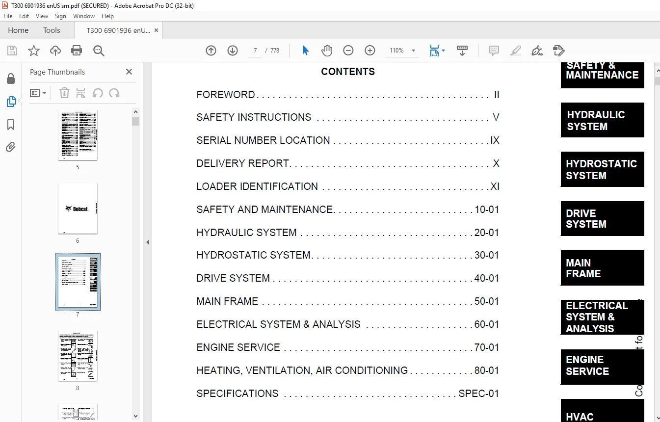
TABLE OF CONTENTS:
Bobcat T300 Turbo T300 Turbo High Flow Loader Service Manual 6901936 (10-12) – PDF DOWNLOAD
MAINTENANCE SAFETY 3
ALPHABETICAL INDEX 5
CONTENTS 7
FOREWORD 8
SAFETY INSTRUCTIONS 11
Fire Prevention 13
SERIAL NUMBER LOCATION 15
Loader Serial Number 15
Engine Serial Number 15
DELIVERY REPORT 16
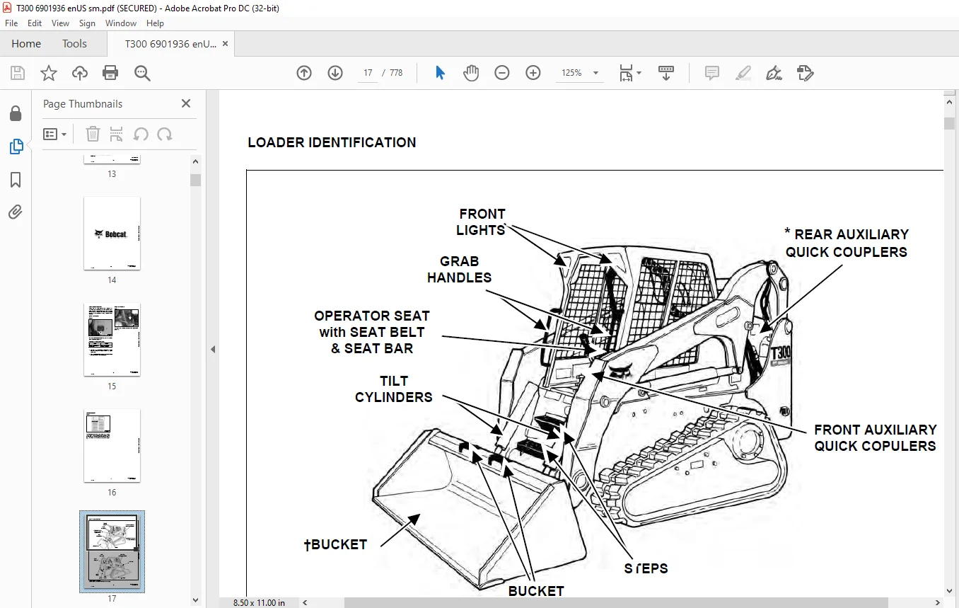
LOADER IDENTIFICATION 17
SAFETY AND MAINTENANCE 19
LIFTING AND BLOCKING THE LOADER 21
Procedure 21
LIFT ARM SUPPORT DEVICE 23
Installing The Lift Arm Support Device 23
Removing The Lift Arm Support Device 24
OPERATOR CAB 25
Description 25
Raising The Operator Cab 25
Lowering The Operator Cab 26
Emergency Exit 26
TRANSPORTING THE BOBCAT LOADER 29
Procedure 29
REMOTE START 31
Procedure For Loader W/O Attachments Control Harness 31
Procedure For Loader With Attachments Control Harness 32
Procedure 33
SERVICE SCHEDULE 35
Chart 35
AIR CLEANER SERVICE 37
Replacing Filter Element 37
ENGINE COOLING SYSTEM 39
Cleaning Cooling System 39
FUEL SYSTEM 41
Fuel Specifications 41
Filling The Fuel Tank 41
Fuel Filter 42
Removing Air From The Fuel System 42
ENGINE LUBRICATION SYSTEM 43
Checking Engine Oil 43
Oil Chart 43
Replacing Oil And Filter 43
HYDRAULIC/HYDROSTATIC SYSTEM 45
Checking And Adding Fluid 45
Hydraulic/Hydrostatic Filter Replacement 45
Replacing Hydraulic Fluid And Case Drain Filters 46
FAN GEARBOX 49
Checking And Adding Oil 49
BOB-TACH 51
Inspection And Maintenance 51
POWER BOB-TACH 53
Inspection And Maintenance 53
LUBRICATING THE LOADER 55
Procedure 55
HYDRAULIC SYSTEM 59
HYDRAULIC/HYDROSTATIC SCHEMATICS 65
HYDRAULIC SYSTEM INFORMATION 77
Troubleshooting 81
Tightening Procedure 82
CYLINDER (LIFT) 83
Checking 83
Removal And Installation 83
Parts Identification 85
Disassembly 86
Assembly 87
CYLINDER (TILT) 91
Checking 91
Removal And Installation 91
Base Pin Removal And Installation 93
Parts Identification 94
Disassembly 95
Assembly 96
CYLINDER (POWER BOB-TACH) 99
Checking 99
Removal And Installation 100
Parts Identification 101
Disassembly 102
Assembly 103
MAIN RELIEF VALVE (FOOT CONTROL) 107
Checking The Main Relief Valve At Front Aux Hyd 107
Removal And Installation 108
Adjustment 108
MAIN RELIEF VALVE (ACS) 109
Checking The Main Relief Valve At Front Aux Hyd 109
Removal And Installation 110
Adjustment 111
HYDRAULIC CONTROL VALVE (FOOT CONTROL) 113
Removal And Installation 113
BICS™ Valve, Removal And Installation 117
BICS™ Valve, Lift Arm By-Pass Orifice Removal And Installation 118
BICS™ Valve, Check Valve Removal And Installation 119
BICS™ Valve, Check Valve Removal And Installation (Cont’d) 120
BICS™ Valve, Lock Valve Removal And Installation 120
BICS™ Valve, Lock Valve Removal And Installation (Cont’d) 121
BICS™ Valve, Solenoid Removal And Installation 121
BICS™ Valve, Solenoid Removal And Installation (Cont’d) 122
BICS™ Valve, Solenoid Testing 122
BICS™ Valve, Solenoid Testing 123
Identification Chart 123
Load Check Valve 123
Main Relief Valve 124
Main Relief Valve (Cont’d) 125
Port Relief Valve, Tilt Spool 125
Port Relief Valve, Lift Spool 125
Port Relief Valve, Lift Spool (Cont’d) 126
Anti-Cavitation Valve/Port Relief Valve, Tilt Spool 126
Anti-Cavitation Valve, Lift Spool 126
Anti-Cavitation Valve, Lift Spool (Cont’d) 127
Rubber Boot 127
Lift And Tilt Lock Block 127
Lift And Tilt Lock Block (Cont’d) 128
Lift Spool And Detent Removal 128
Lift Spool And Detent (Cont’d) 130
Lift Spool And Detent (Cont’d) 136
Lift Spool And Detent (Cont’d) 137
Tilt Spool Removal And Installation 137
Auxiliary Spool Removal And Installation 139
Auxiliary Plug Removal And Installation 141
Auxiliary Electric Solenoid Disassembly 142
Port-Auxiliary Section Removal And Installation 143
Cleaning And Inspection 144
HYDRAULIC CONTROL VALVE (ADVANCED CONTROL SYSTEM) (ACS) 145
Actuator Removal And Installation (In Loader) 145
Actuator Removal And Installation (Out Of Loader) 148
Removal And Installation 149
BICS™ Valve, Removal And Installation 153
BICS™ Valve, Lift Arm By-Pass Orifice Disassembly And Assembly 155
BICS™ Valve, Check Valve Disassembly And Assembly 156
BICS™ Valve, Lock Valve Disassembly And Assembly 157
BICS™ Valve, Solenoid Disassembly And Assembly 158
BICS™ Valve, Solenoid Testing 159
Identification Chart 160
Lift Base End Restrictor 161
Load Check Valve 161
Main Relief Valve 162
Port Relief Valve 163
Anti-Cavitation Valve/Port Relief Valve 164
Anti-Cavitation Valve 165
Lift Spool Removal 166
Lift Spool Removal And Installation 167
Lift and Tilt Spool Disassembly And Assembly 168
Auxiliary Spool Removal And Installation 169
Auxiliary Electric Solenoid Disassembly 170
Port-Auxiliary Section Disassembly 171
Cleaning And Inspection 171
LIFT ARM BY-PASS CONTROL VALVE 173
Inspecting 173
Additional Inspection For Loaders W/Advanced Hand Controls 173
Removal And Installation 173
Disassembly And Assembly 174
HYDRAULIC PUMP 175
Check The Output Of The Hydraulic Pump W/O Power Bob-Tach (S/N 521911523 & Below) 175
Check The Output Of The Hydraulic Pump W/Power Bob-Tach (S/N 521911523 & Below) 177
Removal And Installation 178
HYDRAULIC PUMP (CONT’D) 179
Check The Output Of The Hydraulic Pump (S/N 521911524 & Above) 179
Removal And Installation 180
Identification 182
Disassembly And Assembly 183
HYDRAULIC PUMP (CHARGE) 191
Check The Output Of The Hydraulic Pump 191
Check The Output Of The Hydraulic Pump (Cont’d) 193
HYDRAULIC PUMP (HI FLOW) (S/N 521911523 & BELOW) 195
Hydraulic Pump Test 195
Inline Hydraulic Pump Test (Standard) 196
High Flow Relief Adjustment Procedure 200
High Flow Relief Valve Removal and Installation 202
Removal And Installation 204
Identification 206
Disassembly And Assembly 207
HYDRAULIC PUMP (HI FLOW) (S/N 521911524 & ABOVE) 221
Hydraulic Pump Test 221
Inline Hydraulic Pump Test (Standard) 222
Inline Hydraulic Pump Test (High Flow) 224
High Flow Relief Adjustment Procedure 226
High Flow Relief Valve Removal and Installation 228
Removal And Installation 230
Identification 232
Disassembly And Assembly 233
HYDRAULIC/HYDROSTATIC FILTER 247
Housing Removal And Installation 247
Mount Removal And Installation 248
HYDRAULIC FLUID RESERVOIR 249
Fluid Removal 249
Removal And Installation 249
Hydraulic Fluid Screen 252
BUCKET POSITION VALVE 253
Solenoid Removal And Installation 253
Solenoid Testing 253
Removal And Installation 254
Disassembly And Assembly 254
REAR AUXILIARY DIVERTER VALVE (EARLY MODELS) 257
Removal and Installation 257
Disassembly and Assembly 259
Inspection 259
Solenoid Testing 260
Assembly 260
REAR AUXILIARY DIVERTER (LATER MODELS) 261
Removal and Installation 261
Disassembly And Assembly 263
Solenoid Testing 268
Inspection 268
POWER BOB-TACH BLOCK (EARLY MODELS) 269
Removal And Installation 269
Disassembly And Assembly 270
POWER BOB-TACH BLOCK (LATER MODELS) 279
Removal And Installation 279
Disassembly And Assembly 280
FRONT AUXILIARY HYDRAULIC COUPLER BLOCK 285
Removal and Installation 285
Disassembly And Assembly 285
HYDROSTATIC SYSTEM 287
HYDROSTATIC SYSTEM INFORMATION 289
Troubleshooting Chart 289
Replenishing Valve Function 290
HYDROSTATIC MOTOR 291
Removal And Installation 291
Parts Identification 294
Disassembly 296
Inspection 304
Assembly 305
Filling 313
CHARGE PRESSURE SENDER 315
Testing 315
Removal and Installation 316
Setting Charge Pressure 317
HYDROSTATIC PUMP 319
Removal And Installation 319
Replenishing/High Pressure Relief Valve 321
Parts Identification (Right Half) 322
Parts Identification (Left Half) 324
Hydraulic Pump Removal And Installation 326
Pump Separation 326
Disassembly 327
Assembly 333
DRIVE BELT 341
Shield Removal And Installation 341
Adjustment 341
Replacement 341
Tensioner Pulley Removal And Installation 342
Tensioner Pulley Tension Spring 344
OIL COOLER (SEAL TO CONNECT) (STC) 345
Hydraulic Oil Cooler Removal and Installation 345
DRIVE SYSTEM 347
BRAKE 349
Switch Operated Parking Brake 349
Block Removal And Installation 349
Block Disassembly And Assembly 350
DRIVE COMPONENTS 351
Track Checking 351
Track Adjustment 352
Track Removal And Installation 353
Track Idler (Front) End Play Specifications 355
Track Idler (Front) Removal And Installation 355
Track Idler (Front) Parts Identification 358
Track Idler (Front) Disassembly 359
Track Idler (Front) Assembly 360
Track Idler (Rear) End Play Specifications 363
Track Idler (Rear) Parts Identification 363
Track Idler (Rear) Removal And Installation 363
Track Idler (Rear) Disassembly 364
Track Idler (Rear) Assembly 366
Track Roller Assembly End Play Specifications 367
Track Roller Parts Identification 367
Track Roller Removal And Installation 367
Track Roller Disassembly 368
Track Roller Assembly 369
Track Housing Removal And Installation 371
Track Damage Identification 372
MAIN FRAME 383
SEAT BAR 385
Removal And Installation 385
Assembling Components 386
Compression Spring Disassembly And Assembly 387
OPERATOR CAB 389
Gas Cylinder Removal And Installation 389
Gas Cylinder Bracket Disassembly And Assembly 391
Removal And Installation 391
OPERATOR SEAT 395
Removal And Installation 395
Seat Belt Removal And Installation 395
OPERATOR SEAT (SUSPENSION) 397
Removal And Installation 397
Slide Rail Removal And Installation 398
Cushion Removal And Installation 398
Back Removal And Installation 399
Shock Removal And Installation 400
BOB-TACH 401
Removal And Installation 401
Bob-Tach Lever And Wedge 403
POWER BOB-TACH 405
Removal And Installation 405
Power Bob-Tach Lever And Wedge 407
Pivot Pin Bushing And Seal Replacement 409
LIFT ARMS 411
Stabilizer Bar Removal And Installation 411
Link Removal And Installation 412
Removal And Installation 413
Installation Of Lift Arms 415
REAR GRILL 417
Removal And Installation 417
REAR DOOR 419
Removal And Installation 419
Adjusting The Rear Door Latch 420
FUEL TANK 421
Removal And Installation 421
Fuel Level Sender 423
CONTROL PEDALS 425
Removal And Installation 425
Pedal Adjustment 425
CONTROL PEDALS (ACS) 427
Foot Sensor Removal And Installation 427
Foot Pedal Removal And Installation 428
Foot Pedal Linkage Disassembly And Assembly 428
CONTROL PANEL 429
Removal And Installation 429
Shock Removal And Installation 431
Shaft Removal And Installation 431
Shaft Disassembly And Assembly 431
Linkage Removal And Installation 433
Linkage Neutral Adjustment 436
CONTROL HANDLE 443
Lever Removal And Installation 443
Steering Lever Boot 443
CONTROL HANDLE (ADVANCED CONTROL SYSTEM) (ACS) SELECTABLE HAND/FOOT CONTROL 445
Components Identification 445
Handle Sensor Removal And Installation 445
Control Handle Removal And Installation 448
Control Handle Disassembly And Assembly 449
Control Lever Removal And Installation 450
Control Lever Boot 451
INSIDE ACCESS PANEL 453
Removal And Installation (Left) 453
ELECTRICAL SYSTEM & ANALYSIS 455
ELECTRICAL SCHEMATICS 459
ELECTRICAL SYSTEM INFORMATION 465
Troubleshooting 467
Description 468
Fuse Location 470
Relay Switch Location 470
Solenoid Test 471
BATTERY 473
Removal And Installation 473
Servicing The Electrical System 475
Using A Booster Battery (Jump Starting) 476
ALTERNATOR 477
Adjusting The Alternator Belt 477
Alternator Identification 477
Charging System Check 478
Alternator Voltage Test 479
Low Voltage Test 479
High Voltage Test 480
Removal And Installation 480
Rectifier Continuity (Diode) Test 481
Alternator Regulator Test 482
Disassembly 483
Stator Continuity Test 483
Stator Ground Test 483
Rotor Continuity Test 484
Rotor Ground Test 484
Assembly 484
STARTER 485
Removal And Installation 485
Parts Identification 486
Checking 487
Disassembly And Assembly 488
Inspection And Repair 491
No Load Test 494
INSTRUMENT PANEL 495
Left Panel 495
Right Panel (Standard) (With Key Switch) 496
Right Panel (Deluxe) (With Keyless Start) 497
Right Panel Setup Display Options (Deluxe) 499
Deluxe Panel Setup 500
Passwords (Deluxe) 500
Option And Field Accessory Panels (If Equipped) 502
Standard Panel Removal And Installation (Right Side) 503
Deluxe Panel Removal And Installation (Right Side) 504
Standard & Deluxe Panel Removal And Installation (Left Side) 505
Front Accessory Panel Removal And Installation 506
LIGHTS 507
Front Removal And Installation 507
Rear Removal And Installation 507
BOBCAT CONTROLLER 510
Identification Chart 510
Removal And Installation 512
DIAGNOSTICS SERVICE CODES 513
Display 513
Number Codes List 514
BICS™ SYSTEM 519
Inspecting The BICS™ Controller (Engine STOPPED – Key ON) 519
Inspecting Deactivation Of The Auxiliary Hydraulics System (Engine STOPPED – Key ON) 519
Inspecting The Seat Bar Sensor (Engine RUNNING) 519
Inspecting The Traction Lock (Engine RUNNING) 519
Inspecting The Lift Arm By-Pass Control 520
Additional Inspection For Loaders With Advanced Controls System (ACS) or Selectable Joystick Control (SJC) 520
Troubleshooting 521
Troubleshooting Guide 522
SEAT BAR SENSOR 523
Troubleshooting Chart 523
Test 524
Removal And Installation 525
BICS™ Circuit Test 526
TRACTION LOCK 527
Troubleshooting Chart 527
Description Of The Control System 528
Inspecting The Control System 528
Parking Brake Solenoid Removal And Installation 529
ADVANCED CONTROL SYSTEM (ACS) 531
Components Identification 531
Troubleshooting Guide 533
Controller, Connector And Wire Identification 534
ACS Controller Removal And Installation 535
Handle Sensor Connector 536
Switch Handle Removal 537
Switch Handle Installation 539
Actuators Disassembly And Assembly 542
Handle Lock Solenoid Removal And Installation 543
Handle Lock Solenoid Disassembly And Assembly 543
Handle Lock Solenoid Connector 544
Calibration Of The ACS System 544
Switchable Hand/Foot Controls Calibration Procedure 545
Hand Controls Only Calibration Procedure 546
Foot Sensor Disassembly And Assembly 547
Foot Sensor Connector 548
Foot Lock Solenoid Removal And Installation 548
Foot Lock Solenoid Connector 549
ELECTRICAL/HYDRAULIC CONTROLS REFERENCE 551
Controls Identification Chart 551
FLYWHEEL RPM SENSOR 553
Adjustment 553
ENGINE SERVICE 555
TROUBLESHOOTING 559
Chart 559
ENGINE SPEED CONTROL 561
Removal And Installation 561
Speed Control Cable 562
MUFFLER 565
Removal And Installation 565
AIR CLEANER 567
Housing Removal And Installation 567
RADIATOR 569
Removal And Installation 569
Mount Removal 571
COOLING FAN 573
Drive Tension Pulley Removal And Installation 573
Gearbox/Blower Housing Removal And Installation 574
Gearbox Parts Identification 577
Gearbox Disassembly 578
Gearbox Assembly 583
Gearbox, Checking Backlash 588
ENGINE 591
Removal And Installation 591
Mount Replacement 598
Removal And Installation Tools 599
FLYWHEEL AND HOUSING 601
Flywheel Removal And Installation 601
Ring Gear Removal And Installation 601
Flywheel Housing Removal And Installation 601
RECONDITIONING THE ENGINE 603
Engine Tools Identification Chart 603
Compression Pressure 607
Cylinder Head Clearance 607
Valve Cover And Injector Nozzle Removal And Installation 608
Rocker Arm And Push Rod Disassembly And Assembly 610
Valve Clearance 610
Cylinder Head And Tappet Disassembly And Assembly 611
Selecting Cylinder Head Gasket Disassembly And Assembly 612
Valve Disassembly And Assembly 613
Engine Timing (TDC) 614
Injection Pump Assembly Removal 615
Injection Pump Assembly Installation 618
Injection Pump Removal and Installation 621
Injection Pump Timing 623
Fan Drive Pulley Disassembly And Assembly 626
Water Pump Disassembly And Assembly 626
Gearcase Cover Disassembly And Assembly 627
Idle Gear And Camshaft Disassembly And Assembly 627
Gearcase Plate Disassembly And Assembly 628
Oil Pan And Oil Strainer Disassembly And Assembly 628
Connecting Rod Cap Disassembly And Assembly 629
Piston Disassembly And Assembly 630
Piston Ring And Connecting Rod Disassembly And Assembly 631
Bearing Case Cover Disassembly And Assembly 633
Flywheel Housing Disassembly And Assembly 634
Crankcase No 2 Disassembly And Assembly 634
Crankcase No 1 And No 2 Disassembly And Assembly 635
Crankshaft Disassembly And Assembly 635
Cylinder Head Surface Flatness 635
Cylinder Head Flaw 636
Valve Recessing 636
Valve Lapping 637
Clearance Between Valve Stem And Valve Guide 637
Replacing Valve Guide 638
Correcting Valve And Valve Seat 638
Free Length And Tilt Of Valve Spring 639
Valve Spring Setting Load 639
Oil Clearance Between Rocker Arm Shaft And Bearing 640
Oil Clearance Between Tappet And Tappet Guide Bore 640
Timing Gear Backlash 641
Idler Gear Side Clearance 641
Camshaft Side Clearance 642
Camshaft Alignment 642
Cam Height 642
Oil Clearance Between Idler Gear Shaft And Idler Gearing Bushing 643
Replacing Idler Gear Bushing 644
Piston Pin Bore I D 645
Oil Clearance Between Piston Pin And Small End Bushing 645
Replacing Small End Bushing 646
Clearance Between Piston Ring And Groove 646
Piston Ring Gap 647
Connecting Rod Alignment 647
Crankshaft Side Clearance 648
Crankshaft Alignment 649
Oil Clearance Between Crankpin And Crankpin Bearing 649
Oil Clearance Between Crankshaft Journal And Crankshaft Bearing 651
Replacing Crankshaft Sleeve 652
Cylinder Bore I D 652
Correcting Cylinder (Oversize +0 5 mm) 653
Engine Oil Pressure 653
Rotor Lobe Clearance 654
Clearance Between Outer Rotor And Pump Body 654
Thermostat Valve Opening Temperature 654
Radiator Water Leakage 655
Radiator Cap Air Leakage 655
Thermostat Assembly 655
Intake Air Heater 656
Checking the Turbo Charger 657
Compressor Side 657
Wheel Shaft 657
Axial Clearance 658
Radial Clearance 658
Air Cleaner, Intake Pipe, Inlet Pipe And Muffler 658
Oil Pipe 659
HEATING, VENTILATION, AIR CONDITIONING 661
AIR CONDITIONING SYSTEM FLOW 664
Principals 664
Chart 665
COMPONENTS 667
Identification 667
SAFETY 671
Safety Equipment 671
REGULAR MAINTENANCE 673
Filter Elements Removal And Installation 673
Compressor Drive Belt Inspection 674
Cleaning The Condenser 675
BASIC TROUBLESHOOTING 677
Poor A/C Performance 677
Cleaning The A/C Evaporator Coil & Heater Coil 678
Compressor Drive Belt Inspection 678
Checking The Electrical System 679
Engine Coolant By-Passing The Heater Valve 687
Heater Valve Not Opening Or Closing 688
GENERAL AIR CONDITIONING SERVICE GUIDELINES 689
Compressor Oil 689
Compressor Oil Check 690
Component Replacement And Refrigeration Leaks 691
SYSTEM TROUBLESHOOTING CHART 693
Gauge Pressure Related Troubleshooting 694
Troubleshooting Tree 696
TEMPERATURE/PRESSURE 701
Chart 701
AIR CONDITIONING SERVICE 703
Chart 703
SYSTEM CHARGING AND RECLAMATION 705
Reclamation Procedure 705
Charging Procedure With A Manifold Gauge Set 707
Charging Procedure 708
COMPRESSOR 711
Removal And Installation 711
Compressor Clutch Disassembly 712
CONDENSER 717
Removal And Installation 717
RECEIVER/DRIER 719
Removal And Installation 719
PRESSURE RELIEF VALVE 721
Removal And Installation 721
PRESSURE SWITCH 723
Removal And Installation 723
EVAPORATOR/HEATER UNIT 725
Removal And Installation 725
Disassembly And Assembly 726
THERMOSTAT 727
Removal And Installation 727
EXPANSION VALVE 729
Removal And Installation 729
EVAPORATOR 731
Removal And Installation 731
HEATER COIL 733
Removal And Installation With A/C 733
Removal And Installation Without A/C 734
BLOWER FAN 735
Removal And Installation 735
Disassembly And Assembly 736
Wire Connector Removal and Installation 738
HEATER VALVE 741
Removal and Installation 741
Disassembly And Assembly 742
SPECIFICATIONS 745
LOADER SPECIFICATIONS (T300) 747
Machine Dimensions 747
Performance 748
Controls 748
Engine 748
Hydraulic System 749
Electrical 750
Drive System 750
Capacities 750
Tracks 750
ENGINE SPECIFICATIONS 751
General 751
Fuel System 751
Valve And Valve Timing 751
Valve Spring 752
Piston And Piston Ring 752
Connecting Rod 752
Cylinder Head 753
Crankshaft 753
Cylinder Bore 753
Oil Pump 753
Rocker Arm 754
Tappet 754
Camshaft 754
Thermostat 754
Timing Gear 755
Intake Air Heater 755
TORQUE SPECIFICATIONS FOR BOLTS 757
Torque For General SAE Bolts 757
Torque For General Metric Bolts 758
Torque For Kubota Metric Engine Bolts 759
Tightening Torques For General Use Screws, Bolts And Nuts 759
HYDRAULIC CONNECTION SPECIFICATIONS 761
O-ring Face Seal Connection 761
Straight Thread O-ring Fitting 762
Tubelines And Hoses 762
Flare Fitting 762
O-ring Flare Fitting 763
Port Seal Fitting 765
HYDRAULIC FLUID SPECIFICATIONS 767
Specifications 767
CONVERSIONS 769
Decimal And Millimeter Equivalents 769
SMR 771
T300-1 771
T300-2 773
T300-3 775
T300-4 777
Customer Support: [email protected]
PLEASE NOTE:
- This is the SAME exact manual used by your dealers to fix your vehicle.
- The same can be yours in the next 2-3 mins as you will be directed to the download page immediately after paying for the manual.
- Any queries / doubts regarding your purchase, please feel free to contact [email protected]
S.V