Bobcat T450 Skid-Steer Loader Service Manual 6990394 – PDF DOWNLOAD
$35.95
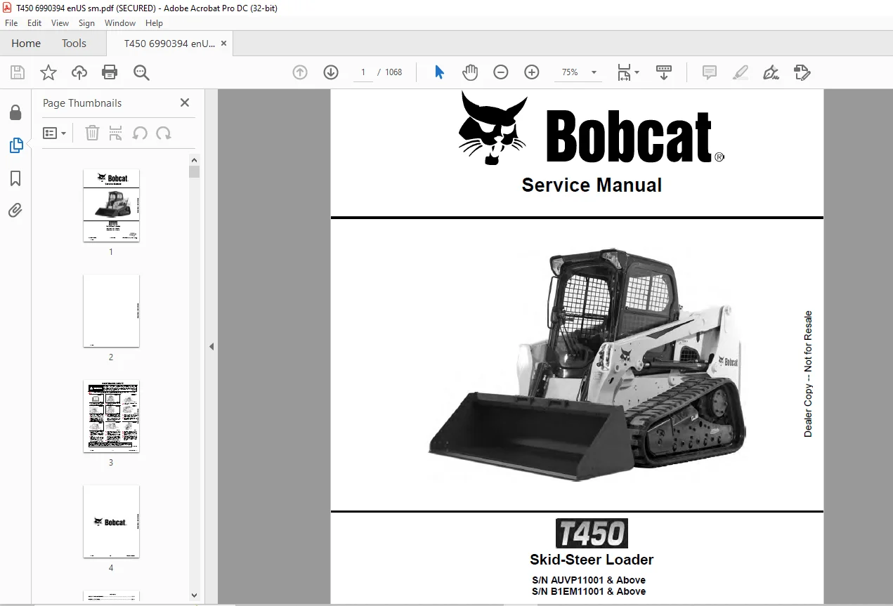
Bobcat T450 Skid-Steer Loader Service Manual 6990394 – PDF DOWNLOAD
S/N AUVP11001 & Above
S/N B1EM11001 & Above
Description
Bobcat T450 Skid-Steer Loader Service Manual 6990394 – PDF DOWNLOAD
FILE DETAILS:
Bobcat T450 Skid-Steer Loader Service Manual 6990394 – PDF DOWNLOAD
Language : English
Pages : 1068
Downloadable : Yes
File Type : PDF
IMAGES PREVIEW OF THE MANUAL:
DESCRIPTION:
Bobcat T450 Skid-Steer Loader Service Manual 6990394 – PDF DOWNLOAD
S/N AUVP11001 & Above
S/N B1EM11001 & Above
FOREWORD:
This manual is for the Bobcat loader mechanic. It provides necessary servicing and adjustment procedures for the Bobcat loader and its component parts and systems. Refer to the Operation & Maintenance Manual for operating instructions, starting procedure, daily checks, etc.
A general inspection of the following items must be made after the loader has had service or repair:
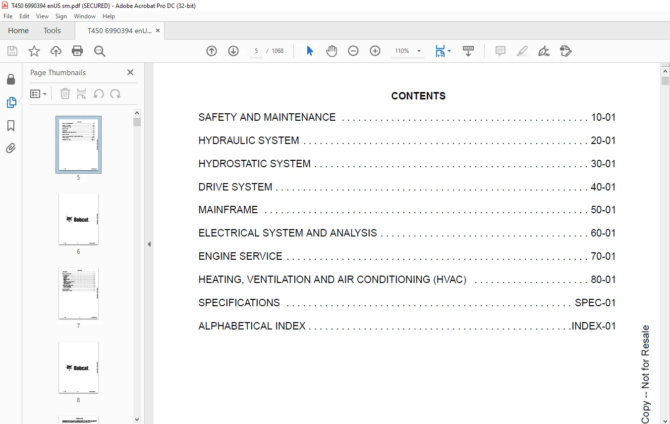
TABLE OF CONTENTS:
Bobcat T450 Skid-Steer Loader Service Manual 6990394 – PDF DOWNLOAD
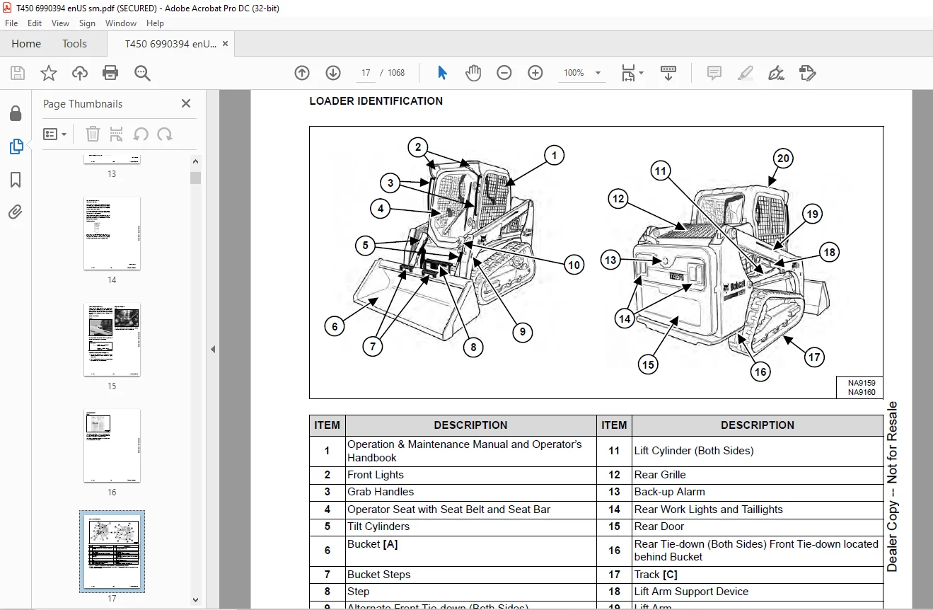
MAINTENANCE SAFETY..............................................................................   3
CONTENTS........................................................................................   5
FOREWORD........................................................................................   7
	FOREWORD....................................................................................   9
	SAFETY INSTRUCTIONS.........................................................................  11
	FIRE PREVENTION.............................................................................  13
		Maintenance.............................................................................  13
		Operation...............................................................................  13
		Electrical..............................................................................  13
		Hydraulic System........................................................................  13
		Fueling.................................................................................  13
		Starting................................................................................  13
		Spark Arrester Exhaust System...........................................................  13
		Welding And Grinding....................................................................  14
		Fire Extinguishers......................................................................  14
	SERIAL NUMBER LOCATIONS.....................................................................  15
		Loader Serial Number....................................................................  15
		Engine Serial Number....................................................................  15
	DELIVERY REPORT.............................................................................  16
	LOADER IDENTIFICATION.......................................................................  17
SAFETY AND MAINTENANCE..........................................................................  19
	LIFTING AND BLOCKING THE LOADER.............................................................  21
		Procedure...............................................................................  21
	LIFT ARM SUPPORT DEVICE.....................................................................  23
		Description.............................................................................  23
		Installing..............................................................................  24
		Removing................................................................................  25
	OPERATOR CAB................................................................................  27
		Description.............................................................................  27
		Cab Door Sensor.........................................................................  27
		Raising.................................................................................  28
		Lowering................................................................................  29
	TRANSPORTING THE LOADER ON A TRAILER........................................................  31
		Loading And Unloading...................................................................  31
		Fastening...............................................................................  31
	TOWING THE LOADER...........................................................................  33
		Procedure...............................................................................  33
	REMOTE START TOOL KIT - MEL1563.............................................................  35
		Remote Start Tool - MEL1563.............................................................  35
		Service Tool Harness Communicator - MEL1566.............................................  37
		Remote Start Procedure..................................................................  37
	REMOTE START TOOL (SERVICE TOOL) KIT - 7217666..............................................  41
		Description.............................................................................  41
		Remote Start Tool (Service Tool) - 7022042..............................................  42
		Loader Service Tool Harness - 6689747...................................................  43
		Computer Service Tool Harness - 6689746.................................................  44
		Remote Start Procedure..................................................................  45
	SERVICE SCHEDULE............................................................................  49
		Maintenance Intervals...................................................................  49
	ENGINE AIR CLEANER..........................................................................  51
		Replacing Filters.......................................................................  51
	ENGINE COOLING SYSTEM.......................................................................  53
		Maintenance Platform....................................................................  53
		Cleaning................................................................................  53
		Checking And Adding Coolant.............................................................  56
		Removing And Replacing Coolant..........................................................  57
	FUEL SYSTEM.................................................................................  59
		Fuel Specifications.....................................................................  59
		Biodiesel Blend Fuel....................................................................  59
		Filling The Fuel Tank...................................................................  60
		Fuel Filter.............................................................................  61
		Removing Air From The Fuel System.......................................................  62
	ENGINE LUBRICATION SYSTEM...................................................................  63
		Checking And Adding Engine Oil..........................................................  63
		Engine Oil Chart........................................................................  63
		Removing And Replacing Oil And Filter...................................................  64
	HYDRAULIC / HYDROSTATIC SYSTEM..............................................................  67
		Checking And Adding Fluid...............................................................  67
		Hydraulic / Hydrostatic Fluid Chart.....................................................  67
		Removing And Replacing Hydraulic Fluid..................................................  68
		Removing And Replacing Hydraulic / Hydrostatic Filter...................................  71
		Removing And Replacing Hydraulic Charge Filter..........................................  72
		Replacing Reservoir Breather Cap........................................................  75
	BOB-TACH (HAND LEVER).......................................................................  77
		Inspection And Maintenance..............................................................  77
	BOB-TACH (POWER)............................................................................  79
		Inspection And Maintenance..............................................................  79
	LUBRICATING THE LOADER......................................................................  81
		Lubrication Locations...................................................................  81
	PIVOT PINS..................................................................................  85
		Inspection And Maintenance..............................................................  85
	LOADER STORAGE AND RETURN TO SERVICE........................................................  87
		Storage.................................................................................  87
		Return To Service.......................................................................  87
	STOPPING THE ENGINE AND LEAVING THE LOADER..................................................  89
		Procedure...............................................................................  89
	EMERGENCY EXIT..............................................................................  91
		Rear Window Identification..............................................................  91
		Rear Window Removal (Latches)...........................................................  91
		Rear Window Removal (Rubber Cord).......................................................  92
		External Access (Rear Window With Latches)..............................................  92
		External Access (Rear Window With Rubber Cord)..........................................  93
		Front Door..............................................................................  93
	SEAT BELT...................................................................................  95
		Inspection And Maintenance..............................................................  95
HYDRAULIC SYSTEM................................................................................  97
	HYDRAULIC / HYDROSTATIC SCHEMATICS.......................................................... 101
	HYDRAULIC SYSTEM INFORMATION................................................................ 117
		Glossary Of Hydraulic / Hydrostatic Symbols............................................. 117
		Troubleshooting......................................................................... 121
	CYLINDER (LIFT)............................................................................. 123
		Testing................................................................................. 123
		Removal And Installation................................................................ 124
		Parts Identification.................................................................... 126
		Disassembly............................................................................. 127
		Assembly................................................................................ 129
	CYLINDER (TILT)............................................................................. 133
		Testing................................................................................. 133
		Removal And Installation................................................................ 134
		Base End Pivot Pin Removal And Installation............................................. 135
		Parts Identification.................................................................... 136
		Disassembly............................................................................. 137
		Assembly................................................................................ 139
	CYLINDER (LIFT) (B1EM11240 & ABOVE)......................................................... 143
		Testing................................................................................. 143
		Removal And Installation................................................................ 144
		Parts Identification.................................................................... 146
		Disassembly............................................................................. 147
		Assembly................................................................................ 149
	CYLINDER (TILT) (B1EM11240 & ABOVE)......................................................... 153
		Testing................................................................................. 153
		Removal And Installation................................................................ 154
		Base End Pivot Pin Removal And Installation............................................. 155
		Parts Identification.................................................................... 156
		Disassembly............................................................................. 157
		Assembly................................................................................ 159
	CYLINDER (BOB-TACH)......................................................................... 163
		Testing................................................................................. 163
		Removal And Installation................................................................ 164
		Parts Identification.................................................................... 165
		Disassembly............................................................................. 166
		Assembly................................................................................ 167
	MAIN RELIEF VALVE........................................................................... 171
		Description............................................................................. 171
		Testing................................................................................. 172
		Adjusting............................................................................... 174
		Removal And Installation................................................................ 175
	HYDRAULIC CONTROL VALVE (STANDARD).......................................................... 177
		Description............................................................................. 177
		Removal And Installation................................................................ 178
		Mount Bracket Removal And Installation.................................................. 181
		Identification Chart.................................................................... 182
		Lift Load Check Valve Removal And Installation.......................................... 183
		Load Check Valve Removal And Installation (Tilt And Auxiliary).......................... 184
		Anti-Cavitation Valve Removal And Installation (Lift, Rod End).......................... 185
		Port Relief / Anti-Cavitation Valve Removal And Installation (Lift, Base End)........... 185
		Port Relief / Anti-Cavitation Valve Removal And Installation (Tilt, Base End)........... 186
		Port Relief / Anti-Cavitation Valve Removal And Installation (Tilt, Rod End)............ 186
		Port Relief Valve Removal And Installation.............................................. 187
		Plug Removal And Installation........................................................... 189
		Rubber Boot Removal And Installation.................................................... 190
		End Cap Block Removal And Installation.................................................. 190
		Lift Spool And Detent Removal And Installation.......................................... 191
		Tilt Spool Removal And Installation..................................................... 199
		Auxiliary Spool Removal And Installation................................................ 201
		Auxiliary Solenoid Removal And Installation............................................. 202
		Solenoid Removal And Installation....................................................... 203
		Lock Valve Removal And Installation..................................................... 204
		Lift Arm Bypass Orifice Removal And Installation........................................ 206
		Main Relief Valve Removal And Installation.............................................. 206
		Check Valve Removal And Installation.................................................... 207
	HYDRAULIC CONTROL VALVE (ACS) OR (SJC)...................................................... 209
		Description............................................................................. 209
		Removal And Installation................................................................ 209
		Actuator Removal And Installation (In Loader)........................................... 212
		Actuator Removal And Installation (Out Of Loader)....................................... 213
		Identification Chart.................................................................... 216
		Mount Bracket Removal And Installation.................................................. 217
		Lift Load Check Valve Removal And Installation.......................................... 217
		Load Check Valve Removal And Installation (Tilt And Auxiliary).......................... 218
		Anti-Cavitation Valve Removal And Installation (Lift, Rod End).......................... 219
		Port Relief / Anti-Cavitation Valve Removal And Installation (Lift, Base End)........... 219
		Port Relief / Anti-Cavitation Valve Removal And Installation (Tilt, Base End)........... 220
		Port Relief / Anti-Cavitation Valve Removal And Installation (Tilt, Rod End)............ 220
		Port Relief Valve Removal And Installation.............................................. 221
		Plug Removal And Installation........................................................... 223
		End Cap Block Removal And Installation.................................................. 224
		Lift Spool Removal And Installation..................................................... 224
		Lift Spool Disassembly And Assembly..................................................... 226
		Tilt Spool Removal And Installation..................................................... 227
		Tilt Spool Disassembly And Assembly..................................................... 228
		Auxiliary Spool Removal And Installation................................................ 229
		Auxiliary Solenoid Removal And Installation............................................. 230
		Solenoid Removal And Installation....................................................... 231
		Lock Valve Removal And Installation..................................................... 232
		Lift Arm Bypass Orifice Removal And Installation........................................ 234
		Main Relief Valve Removal And Installation.............................................. 234
		Check Valve Removal And Installation.................................................... 235
	LIFT ARM BYPASS CONTROL VALVE............................................................... 237
		Description............................................................................. 237
		Testing................................................................................. 237
		Removal And Installation................................................................ 238
		Bracket Removal And Installation........................................................ 239
		Disassembly And Assembly................................................................ 239
	HYDRAULIC PUMP.............................................................................. 241
		Description............................................................................. 241
		Pump Test At Quick Couplers............................................................. 242
		Direct Pump Test (Standard Section)..................................................... 244
		Direct Pump Test (Charge Section)....................................................... 246
		Removal And Installation................................................................ 248
		Hydraulic Pump Startup.................................................................. 250
		Parts Identification.................................................................... 251
		Disassembly And Assembly................................................................ 252
	HYDRAULIC / HYDROSTATIC FILTERS............................................................. 253
		Description............................................................................. 253
		Housing Removal And Installation........................................................ 253
	HYDRAULIC FLUID RESERVOIR................................................................... 255
		Description............................................................................. 255
		Removal And Installation................................................................ 255
		Hydraulic Fluid Screen.................................................................. 256
		Gauge Removal And Installation.......................................................... 256
	OIL COOLER.................................................................................. 257
		Removal And Installation................................................................ 257
	BUCKET POSITION VALVE....................................................................... 259
		Description............................................................................. 259
		Solenoid Removal And Installation....................................................... 259
		Solenoid Testing........................................................................ 260
		Removal And Installation................................................................ 260
		Disassembly And Assembly................................................................ 262
	REAR AUXILIARY DIVERTER VALVE............................................................... 263
		Description............................................................................. 263
		Solenoid Testing........................................................................ 263
		Removal And Installation................................................................ 264
		Disassembly And Assembly................................................................ 265
	BOB-TACH (POWER) BLOCK (EARLIER MODELS)..................................................... 271
		Description............................................................................. 271
		Removal And Installation................................................................ 271
		Disassembly And Assembly................................................................ 273
	BOB-TACH (POWER) BLOCK (LATER MODELS)....................................................... 281
		Description............................................................................. 281
		Testing Relief Valve.................................................................... 281
		Removal And Installation................................................................ 283
		Disassembly And Assembly................................................................ 285
	FRONT AUXILIARY HYDRAULIC COUPLER BLOCK..................................................... 291
		Description............................................................................. 291
		Removal And Installation................................................................ 292
		Disassembly And Assembly (FFI/FI)....................................................... 293
		Disassembly And Assembly (FFH/FH)....................................................... 295
HYDROSTATIC SYSTEM.............................................................................. 297
	HYDROSTATIC SYSTEM INFORMATION.............................................................. 299
		Description............................................................................. 299
		Troubleshooting......................................................................... 300
	HYDROSTATIC DRIVE MOTOR..................................................................... 301
		Description............................................................................. 301
		Removing And Replacing Fluid............................................................ 302
		Removal And Installation................................................................ 302
		Parts Identification (MCR5T)............................................................ 304
		Parts Identification (MCR6T) (Two-Speed)................................................ 305
		Disassembly And Assembly................................................................ 306
	CHARGE PRESSURE............................................................................. 317
		Description............................................................................. 317
		Testing................................................................................. 317
		Adjusting............................................................................... 319
		Sender Removal And Installation......................................................... 321
	HYDROSTATIC PUMP............................................................................ 323
		Description............................................................................. 323
		Removal And Installation................................................................ 324
		Hydrostatic Pump Startup................................................................ 325
		Replenishing / High Pressure Relief Valve Removal And Installation...................... 326
		Parts Identification (Left Half)........................................................ 327
		Parts Identification (Right Half)....................................................... 328
		Disassembly............................................................................. 329
		Assembly................................................................................ 336
	HYDROSTATIC PUMP (SJC)...................................................................... 343
		Description............................................................................. 343
		Hydraulic Controller Removal And Installation........................................... 344
		Removal And Installation................................................................ 346
		Hydrostatic Pump Startup................................................................ 347
		Parts Identification.................................................................... 348
		High Pressure Relief And Bypass Valve................................................... 349
		Charge Relief Valve..................................................................... 350
		Disassembly And Assembly................................................................ 351
		Mechanical Neutral Adjustment........................................................... 364
		Hydraulic Controller Neutral Adjustment................................................. 366
	DRIVE BELT.................................................................................. 371
		Belt Adjustment......................................................................... 371
		Belt Replacement........................................................................ 371
		Tensioner Pulley Removal And Installation............................................... 372
		Tensioner Pulley Disassembly And Assembly............................................... 372
	TWO-SPEED / BRAKE VALVE..................................................................... 373
		Description............................................................................. 373
		Valve Block Removal And Installation.................................................... 374
		Valve Block Disassembly And Assembly.................................................... 376
	DRAIN MANIFOLD.............................................................................. 379
		Description............................................................................. 379
		Drain Manifold Removal And Installation................................................. 379
DRIVE SYSTEM.................................................................................... 381
	BRAKE....................................................................................... 383
		Description............................................................................. 383
		Block Removal And Installation.......................................................... 383
		Block Disassembly And Assembly.......................................................... 385
	TRACK UNDERCARRIAGE COMPONENTS.............................................................. 387
		Description............................................................................. 387
		Checking Tension........................................................................ 388
		Adjusting Tension (Earlier Models With Two Track Tension Fittings)...................... 389
		Adjusting Tension (Later Models With One Track Tension Fitting)......................... 391
		Track Removal And Installation.......................................................... 393
		Idler (Front) Removal And Installation.................................................. 395
		Track Tensioner Disassembly And Assembly................................................ 397
		Idler (Rear) Removal And Installation................................................... 399
		Roller Removal And Installation......................................................... 399
		Sprocket Removal And Installation....................................................... 400
	TRACK MAINTENANCE........................................................................... 401
		Track Damage Identification............................................................. 401
MAINFRAME....................................................................................... 413
	SEAT BAR.................................................................................... 417
		Description............................................................................. 417
		Removal And Installation................................................................ 417
		Disassembly And Assembly................................................................ 418
		Compression Spring Disassembly And Assembly............................................. 419
	OPERATOR CAB................................................................................ 421
		Gas Spring Removal And Installation..................................................... 421
		Gas Spring Bracket Disassembly And Assembly............................................. 422
		Removal And Installation................................................................ 422
	OPERATOR SEAT (SUSPENSION).................................................................. 425
		Removal And Installation................................................................ 425
		Slide Rail Removal And Installation..................................................... 425
		Seat Belt Removal And Installation...................................................... 426
		Lower Cushion Removal................................................................... 426
		Lower Cushion Installation.............................................................. 427
		Back Cushion Removal And Installation................................................... 427
		Shock Removal And Installation.......................................................... 428
		3-Point Seat Belt Removal And Installation.............................................. 428
	BOB-TACH (HAND LEVER)....................................................................... 431
		Description............................................................................. 431
		Removal And Installation................................................................ 431
		Lever And Wedge Disassembly And Assembly................................................ 433
		Pivot Pin Bushing And Seal Removal And Installation..................................... 435
	BOB-TACH (POWER)............................................................................ 437
		Description............................................................................. 437
		Removal And Installation................................................................ 437
		Lever And Wedge Disassembly And Assembly................................................ 439
		Pivot Pin Bushing And Seal Removal And Installation..................................... 442
	LIFT ARMS................................................................................... 443
		Removal And Installation................................................................ 443
	REAR GRILLE................................................................................. 447
		Removal................................................................................. 447
		Installation............................................................................ 447
	REAR DOOR (TAILGATE)........................................................................ 449
		Removal And Installation................................................................ 449
		Striker Removal And Installation........................................................ 450
		Striker Disassembly And Assembly........................................................ 450
		Striker (Adjusting)..................................................................... 451
		Latch Removal And Installation.......................................................... 451
	FUEL TANK................................................................................... 453
		Removal And Installation................................................................ 453
		Fuel Level Sender Removal And Installation.............................................. 454
		Fuel Fill Screen Removal And Installation............................................... 454
	CONTROL PEDALS AND LINKAGES................................................................. 455
		Description............................................................................. 455
		Pedal Removal And Installation.......................................................... 455
		Linkage Removal And Installation........................................................ 456
		Pedal (Adjusting)....................................................................... 457
		Floor Pan Removal And Installation...................................................... 458
	CONTROL PEDALS AND LINKAGES (ACS)........................................................... 459
		Description............................................................................. 459
		Pedal Removal And Installation.......................................................... 459
		Linkage Removal And Installation........................................................ 460
		Pedal (Adjusting)....................................................................... 460
		Floor Pan Removal And Installation...................................................... 461
	CONTROL PEDALS AND LINKAGES (SJC)........................................................... 463
		Description............................................................................. 463
	CONTROL PANEL............................................................................... 465
		Description............................................................................. 465
		Removal And Installation................................................................ 466
		Disassembly And Assembly................................................................ 468
		Linkage Removal And Installation........................................................ 470
		Pintle Arm Disassembly And Assembly..................................................... 473
		Linkage Neutral (Adjusting)............................................................. 474
		Linkage Travel (Adjusting).............................................................. 477
		Shock Removal And Installation.......................................................... 481
	CONTROL PANEL (SJC)......................................................................... 483
		Description............................................................................. 483
		Removal And Installation................................................................ 483
	CONTROL HANDLE / LEVER...................................................................... 485
		Description............................................................................. 485
		Lever Removal And Installation.......................................................... 485
		Boot Removal And Installation........................................................... 486
	CONTROL HANDLE / LEVER (ACS)................................................................ 487
		Description............................................................................. 487
		Handle Sensor Removal And Installation.................................................. 487
		Handle Removal And Installation......................................................... 490
		Handle Disassembly And Assembly......................................................... 491
		Lever Removal And Installation.......................................................... 491
		Boot Removal And Installation........................................................... 492
	CONTROL HANDLE / LEVER (SJC)................................................................ 493
		Description............................................................................. 493
		Joystick Testing........................................................................ 493
		Joystick Removal And Installation....................................................... 494
	WINDOW (REAR)............................................................................... 495
		Rear Window Identification.............................................................. 495
		Removal (Rubber Cord)................................................................... 495
		Installation (Rubber Cord).............................................................. 496
		Removal And Installation (Latches)...................................................... 498
		Disassembly And Assembly (Latches)...................................................... 498
	WINDOW (TOP)................................................................................ 499
		Removal And Installation................................................................ 499
	WINDOW (SIDE)............................................................................... 501
		Removal And Installation................................................................ 501
	CAB DOOR.................................................................................... 503
		Description............................................................................. 503
		Removal And Installation................................................................ 503
		Disassembly And Assembly................................................................ 504
		Aligning................................................................................ 505
		Adjusting............................................................................... 506
		Checking Operation...................................................................... 506
	ARMREST..................................................................................... 507
		Description............................................................................. 507
		Removal And Installation................................................................ 508
		Disassembly And Assembly................................................................ 509
	LEFT SIDE LOWER PANEL....................................................................... 511
		Removal And Installation................................................................ 511
		Disassembly And Assembly................................................................ 513
	RIGHT SIDE LOWER PANEL...................................................................... 515
		Removal And Installation................................................................ 515
		Disassembly And Assembly................................................................ 516
	HEADLINER................................................................................... 519
		Removal And Installation................................................................ 519
	REAR FAN DUCT PANEL......................................................................... 521
		Removal And Installation................................................................ 521
ELECTRICAL SYSTEM AND ANALYSIS.................................................................. 523
	ELECTRICAL SCHEMATICS....................................................................... 529
	ELECTRICAL SYSTEM INFORMATION............................................................... 675
		Glossary Of Electrical Symbols.......................................................... 675
		Standard Cab Harness Connectors......................................................... 678
		Deluxe Cab Harness Connectors........................................................... 679
		Mainframe / Engine Start Harness Connectors - Manual Controls........................... 680
		Mainframe / Engine Start Harness Connectors - SJC / ACS Controls........................ 681
		Engine Sensor Harness Connectors........................................................ 682
		Description............................................................................. 683
		Fuse And Relay Location / Identification................................................ 683
		Troubleshooting......................................................................... 686
		Solenoid Testing........................................................................ 687
	BATTERY..................................................................................... 689
		Servicing............................................................................... 689
		Maintaining Battery Charge Level........................................................ 689
		Battery Service During Machine Storage.................................................. 689
		Battery Testing......................................................................... 690
		Battery Charging........................................................................ 690
		Using A Booster Battery (Jump Starting)................................................. 691
		Removal And Installation................................................................ 692
	ALTERNATOR.................................................................................. 697
		Belt Adjustment......................................................................... 697
		Belt Replacement........................................................................ 697
		Charging System Inspection.............................................................. 698
		Alternator Voltage Testing.............................................................. 699
		Low Voltage Testing..................................................................... 699
		High Voltage Testing.................................................................... 700
		Removal And Installation................................................................ 700
		Parts Identification.................................................................... 702
	STARTER..................................................................................... 703
		Testing................................................................................. 703
		Removal And Installation................................................................ 703
		Parts Identification.................................................................... 704
	INSTRUMENT PANELS........................................................................... 705
		Left Panel.............................................................................. 705
		Display Screen.......................................................................... 707
		Right Panel (Standard Key Panel)........................................................ 708
		Right Panel (Keyless Start Panel)....................................................... 709
		Right Panel (Deluxe Instrumentation Panel).............................................. 710
		Left Switch Panel....................................................................... 712
		Right Switch Panel...................................................................... 712
		Left Side Lower Panel................................................................... 713
		Right Side Lower Panel.................................................................. 713
		Left Panel Removal And Installation..................................................... 714
		Right Panel (Standard Key Panel) Removal And Installation............................... 714
		Right Panel (Keyless Start Panel) Removal And Installation.............................. 715
		Right Panel (Deluxe Instrumentation Panel) Removal And Installation..................... 715
		Key Switch Disassembly And Assembly..................................................... 716
		Alarm Disassembly And Assembly.......................................................... 716
		Left Switch Panel Removal And Installation.............................................. 717
		Right Switch Panel Removal And Installation............................................. 717
	LIGHTS...................................................................................... 719
		Front Removal And Installation.......................................................... 719
		Rear Removal And Installation........................................................... 720
		Cab Light Removal And Installation...................................................... 720
	BOBCAT CONTROLLERS (ACS AND AUXILIARY)...................................................... 721
		Description............................................................................. 721
		Connector And Wire Identification....................................................... 722
		Removal And Installation................................................................ 726
	BOBCAT CONTROLLER (GATEWAY)................................................................. 727
		Description............................................................................. 727
		Connector Identification................................................................ 728
		Removal And Installation................................................................ 731
	BOBCAT CONTROLLER (SJC) (DRIVE)............................................................. 733
		Description............................................................................. 733
		Connector Identification................................................................ 734
		Removal And Installation................................................................ 736
	ENGINE CONTROL UNIT (ECU)................................................................... 737
		Description............................................................................. 737
		Cleaning................................................................................ 738
		Removal And Installation................................................................ 739
	DIAGNOSTIC SERVICE CODES.................................................................... 741
		Viewing Service Codes................................................................... 741
		Service Codes List...................................................................... 742
	BOBCAT INTERLOCK CONTROL SYSTEM (BICS™)..................................................... 751
		Description............................................................................. 751
		Inspecting The BICS™ (Engine STOPPED - Key ON).......................................... 752
		Inspecting Deactivation Of The Auxiliary Hydraulics System (Engine STOPPED – Key ON).... 752
		Inspecting The Seat Bar Sensor (Engine RUNNING)......................................... 752
		Inspecting The Traction Lock And Parking Brake (Engine RUNNING)......................... 752
		Inspecting The Lift Arm Bypass Control.................................................. 752
		Inspecting Deactivation Of Lift And Tilt Functions (ACS And SJC)........................ 752
		Troubleshooting......................................................................... 753
	SEAT BAR SENSOR............................................................................. 755
		Description............................................................................. 755
		Troubleshooting......................................................................... 755
		Testing................................................................................. 756
		Removal................................................................................. 757
		Installation............................................................................ 759
		Bobcat Interlock Control System (BICS™) Circuit Test.................................... 760
	TRACTION LOCK............................................................................... 763
		Description............................................................................. 763
		Troubleshooting......................................................................... 764
		Inspecting.............................................................................. 765
	CONTROL SYSTEM (ACS)........................................................................ 767
		Description............................................................................. 767
		Troubleshooting......................................................................... 768
		Handle Sensor Connector Disassembly And Assembly........................................ 769
		Switch Handle Removal................................................................... 770
		Switch Handle Installation.............................................................. 772
		Actuator Connector Disassembly And Assembly............................................. 775
		Handle Lock Solenoid Removal And Installation........................................... 776
		Handle Lock Solenoid Disassembly And Assembly........................................... 776
		Foot Sensor Removal And Installation.................................................... 777
		Foot Sensor Disassembly And Assembly.................................................... 778
		Foot Sensor Lock Solenoid Removal And Installation...................................... 778
	ELECTRICAL / HYDRAULIC CONTROLS............................................................. 779
		Identification Chart.................................................................... 779
		Description............................................................................. 780
		Identification Chart ACD Group 0........................................................ 781
		Identification Chart ACD Group 1........................................................ 782
		Identification Chart ACD Group 2........................................................ 783
		Identification Chart ACD Group 3........................................................ 784
	ELECTRICAL / HYDRAULIC CONTROLS (ACS)....................................................... 785
		Identification Chart.................................................................... 785
		Description............................................................................. 786
		Identification Chart ACD Group 0........................................................ 787
		Identification Chart ACD Group 1........................................................ 788
		Identification Chart ACD Group 2........................................................ 789
		Identification Chart ACD Group 3........................................................ 790
	ELECTRICAL / HYDRAULIC CONTROLS (SJC)....................................................... 791
		Identification Chart.................................................................... 791
		Description............................................................................. 792
		Identification Chart ACD Group 0........................................................ 793
		Identification Chart ACD Group 1........................................................ 794
		Identification Chart ACD Group 2........................................................ 795
		Identification Chart ACD Group 3........................................................ 796
	SERVICE PC (LAPTOP COMPUTER)................................................................ 797
		Connecting Remote Start Tool............................................................ 797
		Connecting Remote Start Tool (Service Tool)............................................. 797
	CALIBRATION................................................................................. 799
		Description............................................................................. 799
		Actuator Testing........................................................................ 799
		Lift And Tilt Calibration (SJC)......................................................... 802
		Hydrostatic Pump Calibration (SJC)...................................................... 804
		Lift And Tilt Calibration (ACS)......................................................... 809
	STEERING DRIFT COMPENSATION (OPERATOR MODE)................................................. 811
		Description............................................................................. 811
		Operation............................................................................... 811
	STEERING DRIFT COMPENSATION (SERVICE MODE).................................................. 813
		Description............................................................................. 813
		Operation............................................................................... 813
	CONTROL PANEL SETUP......................................................................... 815
		Right Panel Setup (Deluxe Instrumentation Panel)........................................ 815
	PASSWORD SETUP (DELUXE INSTRUMENTATION PANEL)............................................... 819
		Password Description.................................................................... 819
		Changing The Owner Password............................................................. 819
		Changing The User Passwords............................................................. 820
		Password Lockout Feature................................................................ 820
	PASSWORD SETUP (KEYLESS START PANEL)........................................................ 821
		Password Description.................................................................... 821
		Changing The Owner Password............................................................. 821
		Password Lockout Feature................................................................ 821
	MAINTENANCE CLOCK........................................................................... 823
		Description............................................................................. 823
		Setup................................................................................... 824
		Reset................................................................................... 827
	BACK-UP ALARM SYSTEM........................................................................ 829
		Description............................................................................. 829
		Inspecting.............................................................................. 829
		Adjusting Switch Position............................................................... 830
		Troubleshooting (Standard And ACS)...................................................... 831
		Troubleshooting (Joystick).............................................................. 832
		Alarm Removal And Installation.......................................................... 833
		Switch Removal And Installation......................................................... 833
	FRONT HORN.................................................................................. 835
		Removal And Installation................................................................ 835
		Troubleshooting......................................................................... 836
		Troubleshooting (Joystick).............................................................. 837
	ENGINE SPEED CONTROL (HAND)................................................................. 839
		Removal And Installation................................................................ 839
	ENGINE SPEED CONTROL (FOOT)................................................................. 841
		Removal And Installation................................................................ 841
		Disassembly And Assembly................................................................ 842
		Pedal (Adjusting)....................................................................... 844
		Floor Pan Removal And Installation...................................................... 844
	CAMSHAFT AND CRANKSHAFT POSITION SENSOR..................................................... 845
		Removal And Installation................................................................ 845
ENGINE SERVICE.................................................................................. 847
	ENGINE INFORMATION.......................................................................... 851
		Description............................................................................. 851
		Specifications.......................................................................... 852
		Sensor Location......................................................................... 854
		Torque Values........................................................................... 860
		Troubleshooting......................................................................... 862
		Engine Removal And Installation......................................................... 864
		Engine Mount Replacement................................................................ 874
		Compression - Testing................................................................... 876
	DIESEL OXIDATION CATALYST (DOC)............................................................. 879
		Removal And Installation................................................................ 879
	AIR CLEANER................................................................................. 881
		Housing Removal And Installation........................................................ 881
	ENGINE COOLING SYSTEM....................................................................... 883
		Radiator / Oil Cooler Removal And Installation.......................................... 883
		Hydraulic Fan Description............................................................... 886
		Fan Duct Removal And Installation....................................................... 886
		Hydraulic Fan Motor Assembly Removal And Installation................................... 887
		Fan Removal And Installation............................................................ 888
		Hydraulic Fan Motor Removal And Installation............................................ 889
		Hydraulic Fan Motor Disassembly And Assembly............................................ 890
		Fan Shroud Removal And Installation..................................................... 896
		Water Pump Removal And Installation..................................................... 896
		Thermostat Housing Removal And Installation............................................. 897
		Testing The Thermostat.................................................................. 899
	LUBRICATION SYSTEM.......................................................................... 901
		Description............................................................................. 901
		Oil Pan Removal And Installation........................................................ 902
		Oil Pump Removal And Installation....................................................... 903
		Oil Pump Relief Valve Description....................................................... 903
		Oil Cooler Removal And Installation..................................................... 904
		Oil Filter Head Removal And Installation................................................ 904
		Oil Cooler Bypass Description........................................................... 904
	FUEL SYSTEM................................................................................. 905
		Description............................................................................. 905
		Transfer Pump / High Pressure Pump Removal And Installation............................. 906
		Fuel Cooler Removal And Installation.................................................... 909
		Fuel Bypass Removal And Installation.................................................... 909
		Fuel Injector Removal And Installation.................................................. 910
	CYLINDER HEAD............................................................................... 913
		Glow Plugs Testing...................................................................... 913
		Glow Plug Removal And Installation...................................................... 914
		Valve Clearance Adjustment.............................................................. 915
		Cylinder Head Removal And Installation.................................................. 917
		Cylinder Head Disassembly And Assembly.................................................. 922
		Cylinder Head Inspection................................................................ 923
		Cylinder Head Top Clearance............................................................. 924
		Valve Step Height....................................................................... 925
		Valve Stem Height....................................................................... 925
		Valve Guide............................................................................. 926
		Valve................................................................................... 926
		Valve Spring............................................................................ 927
		Rocker Arm Shaft Disassembly And Assembly............................................... 928
		Rocker Arm Shaft Inspection............................................................. 929
		Push Rod Inspection..................................................................... 929
	CRANKSHAFT AND PISTONS...................................................................... 931
		Piston And Connecting Rod Removal And Installation...................................... 931
		Piston And Connecting Rod Inspection.................................................... 932
		Crankshaft Removal And Installation..................................................... 934
		Cylinder Block Inspection............................................................... 937
		Crankshaft Inspection................................................................... 939
		Connecting Rod Inspection............................................................... 939
		Engine Component Class.................................................................. 940
	CAMSHAFT.................................................................................... 943
		Removal And Installation................................................................ 943
		Inspecting.............................................................................. 944
	GEARCASE.................................................................................... 947
		Gearcase Cover Removal And Installation................................................. 947
		Gear Backlash........................................................................... 948
		Gear Timing............................................................................. 949
		Idle Gear Removal And Installation...................................................... 950
		Idle Gear Inspection.................................................................... 950
	TURBOCHARGER................................................................................ 951
		Description............................................................................. 951
		Removal And Installation................................................................ 951
		Inspection.............................................................................. 954
	FLYWHEEL AND HOUSING........................................................................ 955
		Flywheel Removal And Installation....................................................... 955
		Ring Gear Removal And Installation...................................................... 956
		Housing Removal And Installation........................................................ 956
	EXHAUST GAS RECIRCULATION (EGR) SYSTEM...................................................... 957
		Description............................................................................. 957
		Removal And Installation................................................................ 958
		Disassembly And Assembly................................................................ 962
HEATING, VENTILATION AND AIR CONDITIONING (HVAC)................................................ 965
	AIR CONDITIONING SYSTEM FLOW................................................................ 967
		Description............................................................................. 967
		Chart................................................................................... 968
		Components.............................................................................. 969
		Safety Equipment........................................................................ 972
	REGULAR MAINTENANCE......................................................................... 973
		Filters................................................................................. 973
		Belt Adjustment......................................................................... 974
		Belt Replacement........................................................................ 974
		Air Conditioning Condenser.............................................................. 975
		Air Conditioning Lubrication............................................................ 975
		Air Conditioning Service Chart.......................................................... 976
		Evaporator / Heater Coil................................................................ 977
	TROUBLESHOOTING............................................................................. 979
		Blower Motor Does Not Operate........................................................... 979
		Blower Motor Operates Normally, But Air Flow Is Insufficient............................ 979
		Insufficient Cooling Although Air Flow And Compressor Operation Are Normal.............. 979
		The Compressor Does Not Operate At All, Or Operates Improperly.......................... 979
		Gauge Pressure Related Troubleshooting.................................................. 980
		Troubleshooting Tree.................................................................... 982
		Temperature / Pressure Chart............................................................ 986
		Poor A/C Performance.................................................................... 988
		HVAC Repair And Leaks................................................................... 989
		Electrical System....................................................................... 990
		Engine Coolant Bypassing The Heater Valve............................................... 996
		Heater Valve Not Opening Or Closing..................................................... 997
	SYSTEM CHARGING AND RECLAMATION............................................................. 999
		Refrigerant Identification.............................................................. 999
		Reclamation And Charging With Recovery / Charging Unit..................................1000
	COMPRESSOR..................................................................................1003
		Removal And Installation................................................................1003
		Oil.....................................................................................1004
		Oil Check...............................................................................1005
	CONDENSER...................................................................................1007
		Removal And Installation................................................................1007
	RECEIVER / DRIER............................................................................1009
		Receiver / Drier Removal And Installation...............................................1009
		Pressure Switch Removal And Installation................................................1010
		Schrader® Valve Removal And Installation................................................1011
	EVAPORATOR / HEATER UNIT....................................................................1013
		Removal And Installation................................................................1013
	THERMOSTAT..................................................................................1015
		Description.............................................................................1015
		Removal And Installation................................................................1016
	EXPANSION VALVE.............................................................................1017
		Removal And Installation................................................................1017
	EVAPORATOR COIL.............................................................................1019
		Removal And Installation................................................................1019
	HEATER COIL.................................................................................1021
		Removal And Installation................................................................1021
	BLOWER FAN..................................................................................1023
		Removal And Installation................................................................1023
		Disassembly And Assembly................................................................1023
	HEATER VALVE................................................................................1027
		Removal And Installation................................................................1027
	EVAPORATOR / HEATER COVER...................................................................1029
		Removing................................................................................1029
		Installing..............................................................................1029
SPECIFICATIONS..................................................................................1031
	(T450) LOADER SPECIFICATIONS................................................................1033
		Machine Dimensions......................................................................1033
		Performance.............................................................................1034
		Engine..................................................................................1034
		Drive System............................................................................1035
		Controls................................................................................1035
		Hydraulic System........................................................................1036
		Electrical System.......................................................................1037
		Capacities..............................................................................1037
		Tracks..................................................................................1038
		Ground Pressure.........................................................................1038
	TECHNICAL SERVICE GUIDE SPECIFICATIONS......................................................1039
		Engine..................................................................................1039
		Engine Torques..........................................................................1039
		Cooling System..........................................................................1039
		Loader Torques..........................................................................1040
		Hydraulic / Hydrostatic System..........................................................1040
		Fuel Consumption........................................................................1040
	TORQUE SPECIFICATIONS FOR BOLTS.............................................................1041
		Torque For General SAE Bolts............................................................1041
		Torque For General Metric Bolts.........................................................1042
	HYDRAULIC CONNECTION SPECIFICATIONS.........................................................1043
		Straight Thread O-ring Fitting..........................................................1043
		Flare Fitting...........................................................................1044
		Tubelines And Hoses.....................................................................1044
	HYDRAULIC / HYDROSTATIC FLUID SPECIFICATIONS................................................1045
		Specifications..........................................................................1045
	CONVERSIONS.................................................................................1047
		Decimal And Millimeter Equivalent Chart.................................................1047
		U.S. To Metric Conversion Chart.........................................................1047
	SERVICE TOOLS REQUIRED......................................................................1049
		Remote Start Tools......................................................................1049
		Hydraulic Tools.........................................................................1050
		Mainframe And Drive Tools...............................................................1053
		Electrical Tools........................................................................1056
		Engine Tools............................................................................1057
		HVAC Tools..............................................................................1062
ALPHABETICAL INDEX..............................................................................1063
Customer Support: [email protected]
PLEASE NOTE:
- This is the SAME exact manual used by your dealers to fix your vehicle.
- The same can be yours in the next 2-3 mins as you will be directed to the download page immediately after paying for the manual.
- Any queries / doubts regarding your purchase, please feel free to contact [email protected]
S.V