Bobcat T76 Compact Track Loader Service Manual SN B4ZZ11001 & Above – PDF DOWNLOAD
$32.95
Bobcat T76 Compact Track Loader Service Manual SN B4ZZ11001 & Above – PDF DOWNLOAD
Description
Bobcat T76 Compact Track Loader Service Manual SN B4ZZ11001 & Above – PDF DOWNLOAD
FILE DETAILS:
Bobcat T76 Compact Track Loader Service Manual SN B4ZZ11001 & Above – PDF DOWNLOAD
Language : English
Pages : 894
Downloadable : Yes
File Type : PDF
DESCRIPTION:
Bobcat T76 Compact Track Loader Service Manual SN B4ZZ11001 & Above – PDF DOWNLOAD
FOREWORD:
This manual is for the Bobcat loader mechanic. It provides necessary servicing and adjustment procedures for the Bobcat loader and its component parts and systems. Refer to the Operation & Maintenance Manual for operating instructions, starting procedure, daily checks, etc.
A general inspection of the following items must be made after the loader has had service or repair:
IMAGES PREVIEW OF THE MANUAL:
TABLE OF CONTENTS:
Bobcat T76 Compact Track Loader Service Manual SN B4ZZ11001 & Above – PDF DOWNLOAD
MAINTENANCE SAFETY 3
CONTENTS 5
FOREWORD 7
FOREWORD 9
SAFETY INSTRUCTIONS 11
FIRE PREVENTION 13
Maintenance 13
Operation 13
Electrical 13
Hydraulic System 13
Fueling 13
Starting 13
Spark Arrester Exhaust System 13
Welding And Grinding 14
Fire Extinguishers 14
SERIAL NUMBER LOCATIONS 15
Machine Serial Number Location 15
Engine Serial Number Location 15
DELIVERY REPORT 16
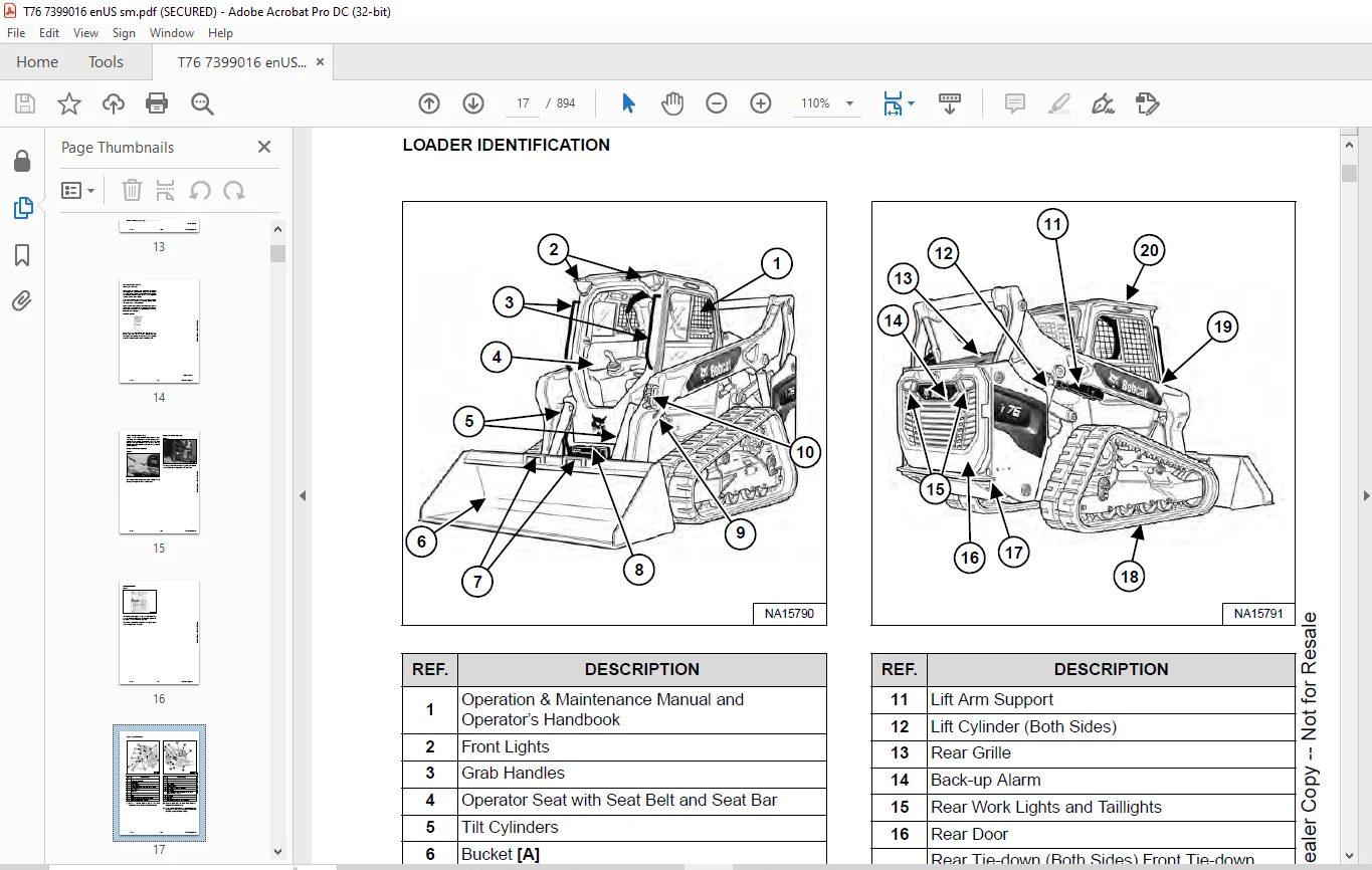
LOADER IDENTIFICATION 17
SAFETY & MAINTENANCE 19
LIFTING AND BLOCKING THE LOADER 23
Procedure 23
LIFT ARM SUPPORT 25
Lift Arm Support Description 25
Installing Lift Arm Support 25
Removing Lift Arm Support 27
OPERATOR CAB 29
Inspecting Operator Cab 29
Cab Door Sensor Description 29
Raising Operator Cab 30
Lowering Operator Cab 31
Clear Side Enclosed Cab Option 33
Inspecting And Maintaining Clear Side Enclosed Cab Option 33
Special Applications Kit 34
Inspecting And Maintaining Special Applications Kit 34
Forestry Door And Window Kit 35
Inspecting And Maintaining Forestry Door And Window Kit 35
TRANSPORTING THE MACHINE 37
Loading And Unloading Machine 37
Fastening Machine To Transport Vehicle 38
TOWING THE MACHINE 39
Procedure 39
REMOTE START TOOL (SERVICE TOOL) KIT – 7217666 41
Description 41
Remote Start Tool (Service Tool) – 7022042 42
Service Tool Harness – 6689747 43
Computer Service Tool Harness – 6689746 44
Remote Start Procedure 45
SERVICE SCHEDULE 49
Maintenance Intervals 49
Service Schedule Symbols 52
ENGINE AIR CLEANER 53
Replacing Engine Air Filter Element (Outer) 53
Replacing Engine Air Filter Element (Inner) 54
ENGINE COOLING SYSTEM 55
Cleaning Engine Cooling System 55
Checking And Adding Coolant 57
Replacing Coolant 58
FUEL SYSTEM 61
Fuel Specifications 61
Biodiesel Blend Fuel 61
Filling The Fuel Tank 62
Removing Water From Main Fuel Filter 63
Replacing Fuel Pre-Filter 64
Replacing Main Fuel Filter 65
Replacing Fuel Tank Vent Filter 67
DIESEL PARTICULATE FILTER (DPF) SYSTEM 69
Description 69
DPF Service Regeneration 69
DPF Cleaning 70
ENGINE LUBRICATION SYSTEM 71
Checking And Adding Engine Oil 71
Engine Oil Chart 71
Replacing Engine Oil And Filter 72
HYDRAULIC SYSTEM 75
Checking And Adding Hydraulic Fluid 75
Hydraulic Fluid Chart 76
Replacing Hydraulic Fluid 77
Replacing Main Hydraulic Filter 81
Replacing Hydraulic Case Drain Filter 83
Replacing Hydraulic Charge Filter 84
Replacing Hydraulic Reservoir Vent Filter 86
BOB-TACH (HAND LEVER) 87
Inspecting And Maintaining Hand Lever Bob-Tach 87
BOB-TACH (POWER) 89
Inspecting And Maintaining Power Bob-Tach 89
MACHINE LUBRICATION 91
Lubricating Grease Fittings 91
PIVOT PINS 93
Checking Pivot Pin Torque 93
MACHINE STORAGE AND RETURN TO SERVICE 95
Machine Extended Storage Procedure 95
Machine Return To Service Procedure 95
STOPPING THE ENGINE AND LEAVING THE MACHINE 97
Procedure 97
EMERGENCY EXITS 99
Removing Rear Window With Latches 99
Removing Rear Window With Rubber Cord 99
Removing Rear Window With Latches From Outside Machine 100
Removing Rear Window With Rubber Cord From Outside Machine 101
Removing Front Door 101
Front Door Reassembly 102
SEAT BELT 103
Inspection And Maintenance 103
HYDRAULIC SYSTEM 105
HYDRAULIC / HYDROSTATIC SCHEMATICS 109
HYDRAULIC SYSTEM INFORMATION 113
Glossary Of Hydraulic Symbols 113
Troubleshooting 117
CYLINDER (LIFT) 119
Testing 119
Removal And Installation 120
Parts Identification 124
Disassembly 125
Assembly 128
CYLINDER (TILT) 133
Testing 133
Removal And Installation 134
Base End Pivot Pin Removal And Installation 136
Parts Identification 137
Disassembly 138
Assembly 141
CYLINDER (BOB-TACH) 145
Testing 145
Removal And Installation 146
Parts Identification 147
Disassembly 148
Assembly 149
MAIN RELIEF VALVE 153
Description 153
Testing 154
Main Relief Valve Removal And Installation 156
HYDRAULIC CONTROL VALVE 157
Description 157
Removal And Installation 157
Actuator Removal And Installation 162
Identification Chart 165
Lift Load Check Valve Removal And Installation 166
Anti-Cavitation Valve Removal And Installation (Lift, Rod End) 168
Port Relief / Anti-Cavitation Valve Removal And Installation (Lift, Base End) 168
Port Relief / Anti-Cavitation Valve Removal And Installation (Tilt, Base End) 169
Port Relief / Anti-Cavitation Valve Removal And Installation (Tilt, Rod End) 169
Port Relief Valve Removal And Installation 170
Plug Removal And Installation 171
End Cap Block Removal And Installation 172
Lift Spool Removal And Installation 172
Lift Spool Disassembly And Assembly 174
Tilt Spool Removal And Installation 175
Tilt Spool Disassembly And Assembly 176
Auxiliary Spool Removal And Installation 177
Solenoid Removal And Installation 178
BICS™ Lock Valve Removal And Installation 179
Lift Arm Bypass Orifice Removal And Installation 181
Main Relief Valve Removal And Installation 181
Screen Fitting Removal And Installation 182
LIFT ARM BYPASS CONTROL VALVE 183
Description 183
Testing 183
Removal And Installation 184
Bracket Removal And Installation 185
Disassembly And Assembly 185
HYDRAULIC PUMP 187
Description 187
Pump Test At Quick Couplers 187
Direct Pump Test (Standard Section) 188
Direct Pump Test (Charge Section) 190
Removal And Installation 192
Hydraulic Pump Startup 195
Parts Identification 196
Disassembly And Assembly 197
HYDRAULIC PUMP (HIGH FLOW) 199
Description 199
Direct Pump Test (Standard Section) 201
Direct Pump Test (Charge Section) 202
Direct Pump Test (High Flow Section) 204
High Flow Relief Valve Adjustment 206
High Flow Relief Valve Removal And Installation 207
Solenoid Removal And Installation 208
Removal And Installation 209
Hydraulic Pump Startup 211
Parts Identification 212
Disassembly And Assembly 213
HYDRAULIC FILTERS 215
Description 215
Main Filter Housing Removal And Installation 215
HYDRAULIC FLUID RESERVOIR 217
Description 217
Removal And Installation 218
OIL COOLER 221
Description 221
Removal And Installation 221
BUCKET POSITION SENSORS 223
Description 223
Removal And Installation 223
REAR AUXILIARY DIVERTER VALVE 225
Description 225
Removal And Installation 225
Disassembly And Assembly 227
BOB-TACH (POWER) BLOCK 233
Description 233
Testing Relief Valve 234
Removal And Installation 236
Disassembly And Assembly 238
FRONT AUXILIARY HYDRAULIC COUPLER BLOCK 243
Description 243
Removal And Installation 244
Disassembly And Assembly 244
AUTOMATIC RIDE CONTROL 247
Description 247
Removal And Installation 248
Checking The Pressure In The Accumulator 250
Adding Nitrogen To The Accumulator 252
HYDROSTATIC SYSTEM 255
HYDROSTATIC SYSTEM INFORMATION 257
Description 257
Troubleshooting 257
HYDROSTATIC DRIVE MOTOR 259
Description 259
Removing And Replacing Fluid 260
Removal And Installation 261
Parts Identification 264
Disassembly And Assembly 265
CHARGE PRESSURE 275
Description 275
Testing 275
Sender Removal And Installation 276
Adjusting And Inspecting (SJC) 277
HYDROSTATIC PUMP 279
Description 279
Port Locations And Gauge Installation 280
Removal And Installation 281
Hydrostatic Pump Startup 284
High Pressure Relief And Bypass Valve 285
Charge Pressure Relief Valve 286
Disassembly And Assembly 287
Mechanical Neutral Adjustment 299
Hydraulic Controller Neutral Adjustment 301
TWO-SPEED / BRAKE VALVE 303
Description 303
Valve Block Removal And Installation 304
Valve Block Disassembly And Assembly 306
DRAIN MANIFOLD 309
Description 309
Drain Manifold Housing Removal And Installation 309
DRIVE SYSTEM 311
BRAKE 313
Description 313
Block Removal And Installation 313
Block Disassembly And Assembly 315
BRAKE (TWO-SPEED) 317
Description 317
TRACK UNDERCARRIAGE COMPONENTS (SOLID-MOUNTED) 319
Description 319
Checking Tension 320
Adjusting Tension 321
Track Removal And Installation 322
Idler (Front) Removal And Installation 325
Track Tensioner Removal And Installation 326
Track Tensioner Disassembly And Assembly 327
Idler (Rear) Removal And Installation 329
Roller Removal And Installation 329
Sprocket Removal And Installation 330
Track Frame Removal And Installation 331
TRACK UNDERCARRIAGE COMPONENTS (TORSION SUSPENSION) 333
Description 333
Checking Tension 335
Adjusting Tension 336
Track Removal And Installation 337
Idler (Front) Removal And Installation 340
Track Tensioner Removal And Installation 341
Track Tensioner Disassembly And Assembly 342
Idler (Rear) Removal And Installation 344
Roller Removal And Installation 344
Sprocket Removal And Installation 345
Track Frame Removal And Installation 346
TRACK MAINTENANCE 351
Track Damage Identification 351
MAINFRAME 363
SEAT BAR 367
Description 367
Removal And Installation 368
Disassembly And Assembly 369
Compression Spring Disassembly And Assembly 370
OPERATOR CAB 371
Gas Spring Removal And Installation 371
Gas Spring Bracket Disassembly And Assembly 372
Removal And Installation 373
OPERATOR SEAT 375
Removal And Installation 375
Seat Belt Removal And Installation (Two Point) 375
Seat Belt Removal And Installation (Three Point) 376
OPERATOR SEAT (SUSPENSION) 379
Removal And Installation 379
Slide Rail Removal And Installation 379
Seat Belt Removal And Installation 380
Lower Cushion Removal 380
Lower Cushion Installation 381
Back Cushion Removal And Installation 381
Shock Removal And Installation 382
3-Point Seat Belt Removal And Installation 382
BOB-TACH (HAND LEVER) 385
Description 385
Removal And Installation 385
Lever And Wedge Disassembly And Assembly 387
Pivot Pin Bushing And Seal Removal And Installation 389
BOB-TACH (POWER) 391
Description 391
Removal And Installation 391
Lever And Wedge Disassembly And Assembly 394
Pivot Pin Bushing And Seal Removal And Installation 395
LIFT ARMS 397
Driver Link Removal And Installation 397
Follower Link Removal And Installation 400
Lift Arm Removal And Installation 402
REAR GRILLE 405
Raising Rear Grille 405
Lowering Rear Grille 406
Shield Removal And Installation 406
REAR DOOR (TAILGATE) 407
Removal And Installation 407
Striker Removal And Installation 408
Striker Disassembly And Assembly 408
Striker (Adjusting) 409
Latch Removal And Installation 409
FUEL TANK 411
Removal And Installation 411
Fuel Level Sender Removal And Installation 413
Fuel Tank Vent Removal And Installation 414
FOOTREST 415
Footrest Removal And Installation (Right Side) 415
Footrest Removal And Installation (Left Side) 415
CONTROL HANDLE (SJC) 417
Description 417
Joystick Testing 417
Joystick Removal And Installation 418
ACCESS PANELS (LOWER) 421
Removal And Installation (Left Side) 421
Removal And Installation (Right Side) 423
ACCESS PANELS (UPPER) 425
Removal And Installation (Center Panel) 425
Removal And Installation (Left Side) 426
Removal And Installation (Right Side) 427
WINDOW (REAR) 429
Removing Rear Window With Latches 429
Removing Rear Window With Rubber Cord 429
Removing Rear Window With Latches From Outside Loader 430
Disassembly And Assembly (Latches) 431
Removal (Rubber Cord) 432
Installation (Rubber Cord) 433
WINDOW (TOP) 435
Removal And Installation 435
WINDOW (SIDE) 437
Removal And Installation 437
CAB DOOR 439
Description 439
Removal And Installation 439
Disassembly And Assembly 440
Aligning 442
Adjusting 442
Checking Operation 443
ARMREST 445
Description 445
Removal And Installation 445
Disassembly And Assembly 447
HEADLINER 449
Removal And Installation 449
ELECTRICAL SYSTEM 453
ELECTRICAL SCHEMATICS 459
ELECTRICAL SYSTEM 483
Glossary Of Electrical Symbols 483
Standard Cab Harness Connectors 486
Deluxe Cab Harness Connectors 487
Mainframe Harness Connectors 488
Electrical System Description 489
Fuse And Relay Identification 490
Solenoid Testing 494
BATTERY 495
Removing And Installing Battery 495
Battery Maintenance 496
Maintaining Battery Charge Level 496
Battery Service During Machine Storage 496
Testing Battery 497
Charging Battery 497
Using A Booster Battery (Jump Starting) 498
ALTERNATOR 499
Adjusting Belt (Machines Without Air Conditioning) 499
Replacing Belt (Machines Without Air Conditioning) 499
Adjusting Belt (Machines With Air Conditioning) 500
Replacing Belt (Machines With Air Conditioning) 500
Charging System Inspection 501
Alternator Voltage Testing 502
Low Voltage Testing 503
High Voltage Testing 503
Removal And Installation (Machines Without Air Conditioning) 504
Removal And Installation (Machines With Air Conditioning) 505
Parts Identification 506
STARTER 507
Testing 507
Removal And Installation 507
Parts Identification 508
INSTRUMENT PANEL IDENTIFICATION 509
Instrument Panel Overview 509
Standard Display 510
Touch Display 512
Left Control Panel 514
Right Control Panel 514
Jog Shuttle (Standard Display) 515
Jog Shuttle (Touch Display) 515
Heating, Ventilation, And Air Conditioning (HVAC) Controls 516
Touch Display Radio Input Ports 516
Keyed Ignition Kit 517
Radio Identification 518
Left Switch Panel Removal And Installation 520
Right Switch Panel Removal And Installation 521
LIGHTS 523
Front Removal And Installation 523
Rear Removal And Installation 523
Cab Light Removal And Installation 524
Side Light Removal And Installation 524
BOBCAT HUB CONTROLLER 525
Description 525
Connector Identification 526
Removal And Installation 529
BOBCAT MID CONTROLLER 533
Description 533
Removal And Installation 534
BOBCAT CONTROLLER (SJC) (DRIVE) 535
Description 535
Removal And Installation 536
ENGINE CONTROL UNIT (ECU) 537
Description 537
Cleaning 538
Removal And Installation 539
DIAGNOSTIC SERVICE CODES 541
Service Codes List 541
BOBCAT INTERLOCK CONTROL SYSTEM (BICS™) 547
Inspecting The Bobcat Interlock Control System (BICS™) 547
Inspecting The Lift Arm Bypass Control 549
SEAT BAR SENSOR 551
Description 551
Troubleshooting 551
Testing 552
Removal And Installation 553
Bobcat Interlock Control System (BICS™) Circuit Test 556
TRACTION LOCK 559
Description 559
Troubleshooting 560
Operating Parking Brake 561
Operating Hydraulic Controls With Parking Brake Engaged 561
ELECTRICAL / HYDRAULIC CONTROLS (SJC) 563
Identification Chart 563
Description 564
Identification Chart ACD Group 0 565
Identification Chart ACD Group 1 566
Identification Chart ACD Group 2 567
Identification Chart ACD Group 3 568
SERVICE PC (LAPTOP COMPUTER) 569
Connecting Remote Start Tool (Service Tool) 569
CALIBRATION 571
Description 571
Actuator Testing 571
Lift And Tilt Calibration (SJC) 574
Adjusting Lift And Tilt Compensation 574
Hydrostatic Pump Calibration (SJC) 577
STEERING DRIFT COMPENSATION 583
Steering Drift Compensation Description 583
Adjusting Steering Drift Compensation 584
NAVIGATION (STANDARD DISPLAY) 587
Navigation Bar 587
Viewing Active Shortcuts 587
VITALS (STANDARD DISPLAY) 589
Vital Detail And Machine Performance 589
SERVICE (STANDARD DISPLAY) 591
Record A Service 591
SETTINGS (STANDARD DISPLAY) 593
Display Settings 593
Machine Settings 594
Language Settings 595
Units 596
Software 597
GAUGES (TOUCH DISPLAY) 599
Vital Detail And Machine Performance 599
Notification Drawer 600
CAMERA (TOUCH DISPLAY) 601
Camera Settings 601
PHONE (TOUCH DISPLAY) 603
AUDIO (TOUCH DISPLAY) 605
SERVICE (TOUCH DISPLAY) 607
Record A Service 607
View Service Schedule 608
View Service Record 609
View Service Codes 610
ATTACHMENTS (TOUCH DISPLAY) 611
Attachment Information 611
SETTINGS (TOUCH DISPLAY) 613
Favorites 613
Display Settings 615
Machine Settings 616
Security Settings 617
Security Settings (Manage Operators) 618
Operator Statistics 622
Job Clocks 623
Language Settings 625
Units 626
Camera Settings 626
Bluetooth® Settings 626
Audio Settings 626
Dealer 627
Software 628
PASSWORD SETUP 629
Security Settings 629
Security Settings (Manage Operators) 630
MAINTENANCE CLOCK 631
Record A Service 631
View Service Codes 632
BACK-UP ALARM SYSTEM 633
Inspecting Back-up Alarm System 633
Troubleshooting (Joystick) 634
Alarm Removal And Installation 635
FRONT HORN 637
Removal And Installation 637
Troubleshooting 638
ENGINE SPEED CONTROL (HAND) 639
Description 639
Removal And Installation 640
ENGINE SPEED CONTROL (FOOT) 641
Description 641
Removal And Installation 641
Disassembly And Assembly 642
CAMSHAFT AND CRANKSHAFT POSITION SENSOR 645
Removal And Installation 645
MACHINE IQ 647
Description 647
Removal And Installation 647
Procedure 648
ENGINE SERVICE 649
ENGINE INFORMATION 653
Description 653
Specifications 654
Sensor Location 656
Torque Values 663
Troubleshooting 665
Engine Removal And Installation 667
Engine Mount Replacement 673
Compression – Testing 675
Injector Signal Testing (In-Line) 677
Oil Pressure Testing (At Turbocharger Oil Inlet) 679
DIESEL PARTICULATE FILTER (DPF) SYSTEM 681
Description 681
DPF Regeneration Status Icons 681
DPF Regeneration Tables 682
Removal And Installation 684
Automatic Regeneration Operation 686
Forced Regeneration Operation 687
Forced Parked Regeneration Operation 688
Inhibit Mode Operation 690
AIR CLEANER 693
Housing Removal And Installation 693
ENGINE COOLING SYSTEM 695
Radiator Cooling Package Removal And Installation 695
Hydraulic Fan Description 699
Reversible Hydraulic Fan Description 699
Hydraulic Fan Motor Assembly Removal And Installation 700
Hydraulic Fan Motor Removal And Installation 703
Hydraulic Fan Motor Disassembly And Assembly 705
Water Pump Removal And Installation 713
Thermostat Housing Removal And Installation 714
Testing The Thermostat 715
LUBRICATION SYSTEM 717
Description 717
Oil Pan Removal And Installation 718
Oil Pump Removal And Installation 719
Oil Pump Relief Valve Description 720
Oil Pump Relief Valve Removal And Installation 720
Oil Cooler Removal And Installation 720
Oil Filter Head Removal And Installation 721
Oil Cooler Bypass Description 723
Oil Cooler Bypass Removal And Installation 723
FUEL SYSTEM 725
Description 725
Fuel Filter Housing Removal And Installation 726
Fuel Lift Pump Removal And Installation 728
Fuel Lift Pump Filter Removal And Installation 729
Transfer Pump / High Pressure Pump Removal And Installation 729
Fuel Temperature Sensor Removal And Installation 731
Fuel Recirculation Valve (FRV) Removal And Installation 732
Fuel Pressure Relief Valve Removal And Installation 732
Fuel Rail Assembly Removal And Installation 733
Fuel Injector Removal And Installation 734
Injector Coding 738
CYLINDER HEAD 739
Glow Plugs Testing 739
Glow Plug Removal And Installation 740
Cylinder Head Removal And Installation 741
Cylinder Head Disassembly And Assembly 744
Cylinder Head Inspection 745
Cylinder Head Top Clearance 746
Valve Step Height 747
Valve Stem Height 747
Valve Guide 748
Valve 748
Valve Spring 749
Rocker Arm Shaft Disassembly And Assembly 750
Rocker Arm Shaft Inspection 751
Push Rod Inspection 751
CRANKSHAFT AND PISTONS 753
Piston And Connecting Rod Removal And Installation 753
Piston And Connecting Rod Inspection 754
Crankshaft Removal And Installation 756
Cylinder Block Inspection 759
Crankshaft Inspection 761
Connecting Rod Inspection 761
Engine Component Class 762
CAMSHAFT 765
Removal And Installation 765
Inspecting 766
GEARCASE 769
Gearcase Cover Removal And Installation 769
Gear Backlash 770
Gear Timing 771
Idle Gear Removal And Installation 772
Idle Gear Inspection 772
TURBOCHARGER 773
Description 773
Removal And Installation 773
Inspection 775
FLYWHEEL AND HOUSING 777
Flywheel Removal And Installation 777
Ring Gear Removal And Installation 778
Housing Removal And Installation 779
EXHAUST GAS RECIRCULATION (EGR) SYSTEM 781
Description 781
Removal And Installation 782
EXHAUST MANIFOLD 785
Removal And Installation 785
HEATING, VENTILATION AND AIR CONDITIONING (HVAC) 787
AIR CONDITIONING SYSTEM FLOW 789
Description 789
Chart 790
Components 791
Safety Equipment 794
REGULAR MAINTENANCE 795
Cleaning HVAC Filters 795
Cleaning Air Conditioning Evaporator And Heater Coil 796
Cleaning Air Conditioning Condenser 797
Lubricating Air Conditioning System 797
Troubleshooting HVAC System 797
Adjusting Belt 798
Replacing Belt 798
Air Conditioning Service Chart 799
TROUBLESHOOTING 801
Blower Motor Does Not Operate 801
Blower Motor Operates Normally, But Air Flow Is Insufficient 801
Insufficient Cooling Although Air Flow And Compressor Operation Are Normal 801
The Compressor Does Not Operate At All, Or Operates Improperly 801
Gauge Pressure Related Troubleshooting 802
Troubleshooting Tree 804
Temperature / Pressure Chart 808
Poor A/C Performance 810
HVAC Repair And Leaks 811
Electrical System 812
Engine Coolant Bypassing The Heater Valve 818
Heater Valve Not Opening Or Closing 819
SYSTEM CHARGING AND RECLAMATION 821
Refrigerant Identification 821
Reclamation And Charging With Recovery / Charging Unit 822
COMPRESSOR 825
Removal And Installation 825
Oil 826
Oil Check 827
CONDENSER 829
Removal And Installation 829
RECEIVER / DRIER 831
Receiver / Drier Removal And Installation 831
EVAPORATOR / HEATER UNIT 833
Removal And Installation 833
THERMOSTAT 835
Description 835
Removal And Installation 836
EXPANSION VALVE 839
Removal And Installation 839
EVAPORATOR COIL 843
Removal And Installation 843
HEATER COIL 847
Removal And Installation 847
BLOWER FAN 849
Removal And Installation 849
Disassembly And Assembly 850
HEATER VALVE 853
Removal And Installation 853
EVAPORATOR / HEATER COVER 855
Removing 855
Installing 856
SPECIFICATIONS 857
LOADER SPECIFICATIONS 859
Machine Dimensions 859
Performance Specifications 861
Engine Specifications 861
Drive System Specifications 862
Control Specifications 862
Hydraulic System Specifications 863
Hydraulic Cylinder Specifications 863
Electrical System Specifications 864
Fluid Capacities 864
Tracks 864
Ground Pressure 864
Engine CO2 Emission Values 864
TECHINCAL SERVICE GUIDE SPECIFICATIONS 865
Engine 865
Engine Torques 865
Cooling System 865
Loader Torques 866
Hydraulic / Hydrostatic System 866
Fuel Consumption 866
TORQUE SPECIFICATIONS FOR BOLTS 867
Torque For General SAE Bolts 867
Torque For General Metric Bolts 868
HYDRAULIC CONNECTION SPECIFICATIONS 869
Straight Thread O-ring Fitting 869
Flare Fitting 870
Tubelines And Hoses 870
HYDRAULIC FLUID SPECIFICATIONS 871
Specifications 871
CONVERSIONS 873
Decimal And Millimeter Equivalent Chart 873
U S To Metric Conversion Chart 873
SERVICE TOOLS REQUIRED 875
Remote Start Tools 875
Hydraulic Tools 876
Mainframe And Drive Tools 879
Electrical Tools 882
Engine Tools 883
HVAC Tools 888
ALPHABETICAL INDEX 889
Questions? Email us: [email protected]
PLEASE NOTE:
- This is the SAME manual used by the dealers to troubleshoot any faults in your vehicle. This can be yours in 2 minutes after the payment is made.
- Contact us at [email protected] should you have any queries before your purchase or that you need any other service / repair / parts operators manual.
S.V