Bobcat T870 Compact Track Loader Service Manual 7318701 – PDF DOWNLOAD
$35.95
Bobcat T870 Compact Track Loader Service Manual 7318701 – PDF DOWNLOAD
S/N B47C11001 & Above
S/N B47L11001 & Above
Description
Bobcat T870 Compact Track Loader Service Manual 7318701 – PDF DOWNLOAD
FILE DETAILS:
Bobcat T870 Compact Track Loader Service Manual 7318701 – PDF DOWNLOAD
Language : English
Pages : 1002
Downloadable : Yes
File Type : PDF
DESCRIPTION:
Bobcat T870 Compact Track Loader Service Manual 7318701 – PDF DOWNLOAD
S/N B47C11001 & Above
S/N B47L11001 & Above
FOREWORD:
This manual is for the Bobcat loader mechanic. It provides necessary servicing and adjustment procedures for the Bobcat loader and its component parts and systems. Refer to the Operation & Maintenance Manual for operating instructions, starting procedure, daily checks, etc.
A general inspection of the following items must be made after the loader has had service or repair:
IMAGES PREVIEW OF THE MANUAL:
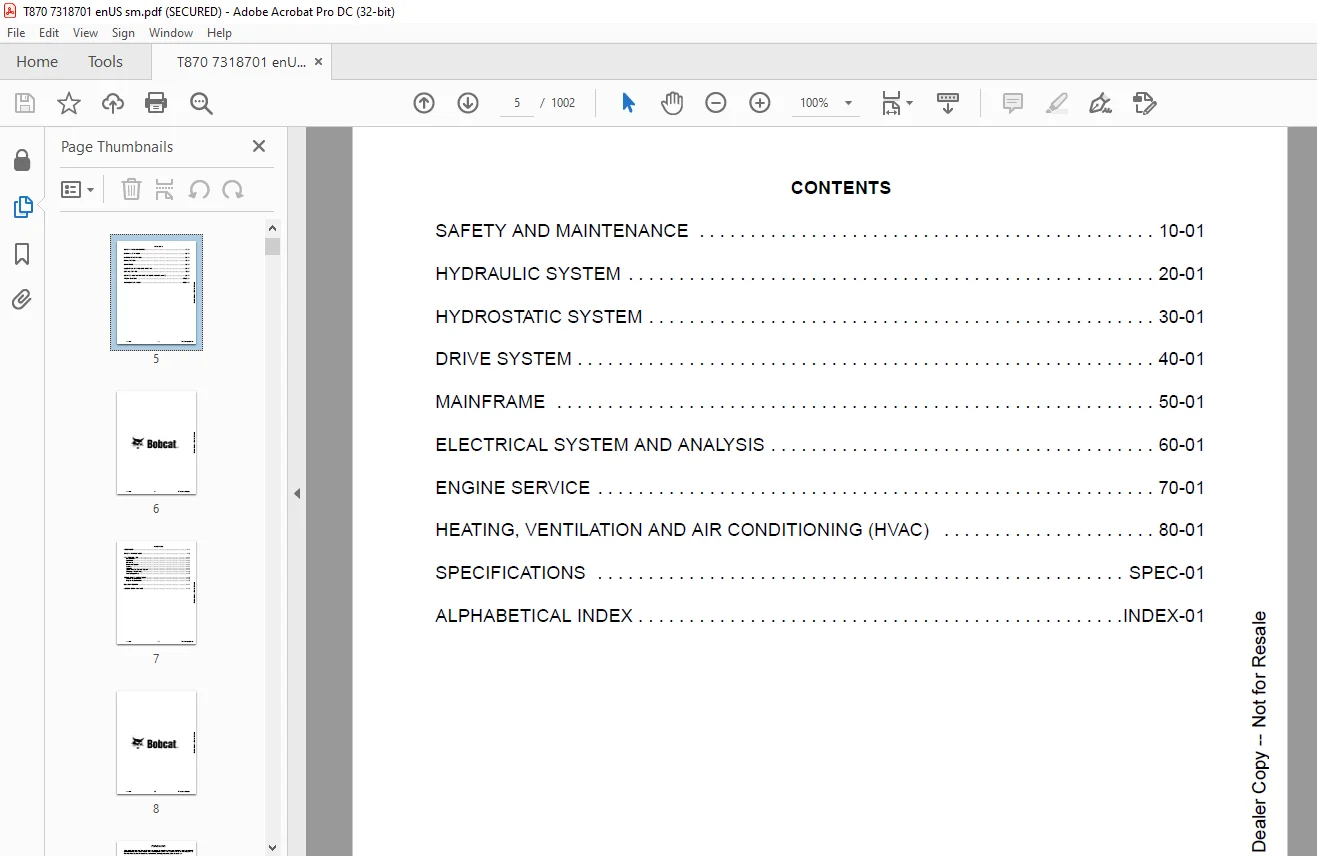
TABLE OF CONTENTS:
Bobcat T870 Compact Track Loader Service Manual 7318701 – PDF DOWNLOAD
MAINTENANCE SAFETY 3
CONTENTS 5
FOREWORD 7
FOREWORD 9
SAFETY INSTRUCTIONS 11
FIRE PREVENTION 13
Maintenance 13
Operation 13
Electrical 13
Hydraulic System 13
Fueling 13
Starting 13
Spark Arrester Exhaust System 13
Welding And Grinding 14
Fire Extinguishers 14
SERIAL NUMBER LOCATIONS 15
Loader Serial Number 15
Engine Serial Number 15
DELIVERY REPORT 16
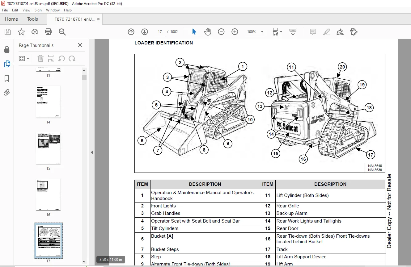
LOADER IDENTIFICATION 17
SAFETY AND MAINTENANCE 19
LIFTING AND BLOCKING THE LOADER 21
Procedure 21
LIFT ARM SUPPORT DEVICE 23
Description 23
Installing 24
Removing 25
OPERATOR CAB 27
Description 27
Raising 27
Lowering 28
Cab Door Sensor 29
Special Applications Kit 30
Special Applications Kit Inspection And Maintenance 30
Forestry Door And Window Kit 31
Forestry Door And Window Kit Inspection And Maintenance 31
TRANSPORTING THE LOADER ON A TRAILER 33
Loading And Unloading 33
Fastening 33
TOWING THE LOADER 35
Procedure 35
REMOTE START TOOL KIT – MEL1563 37
Remote Start Tool – MEL1563 37
Service Tool Harness Communicator – MEL1566 39
Remote Start Procedure 39
REMOTE START TOOL (SERVICE TOOL) KIT – 7217666 43
Description 43
Remote Start Tool (Service Tool) – 7022042 44
Loader Service Tool Harness – 6689747 45
Computer Service Tool Harness – 6689746 46
Remote Start Procedure 47
SERVICE SCHEDULE 51
Maintenance Intervals 51
ENGINE AIR CLEANER 53
Replacing Filter Elements 53
ENGINE COOLING SYSTEM 55
Maintenance Platform 55
Cleaning 55
Checking And Adding Coolant 58
Removing And Replacing Coolant 59
FUEL SYSTEM 61
Fuel Specifications 61
Biodiesel Blend Fuel 61
Filling The Fuel Tank 62
Fuel Filter 63
Removing Air From The Fuel System 64
ENGINE LUBRICATION SYSTEM 65
Checking And Adding Engine Oil 65
Engine Oil Chart 65
Removing And Replacing Oil And Filter 66
HYDRAULIC / HYDROSTATIC SYSTEM 69
Checking And Adding Fluid 69
Hydraulic / Hydrostatic Fluid Chart 69
Removing And Replacing Hydraulic Fluid 70
Removing And Replacing Hydraulic / Hydrostatic Filter 72
Removing And Replacing Hydraulic Charge Filter 73
Replacing Reservoir Breather Cap 74
BOB-TACH (HAND LEVER) 75
Inspection And Maintenance 75
BOB-TACH (POWER) 77
Inspection And Maintenance 77
LUBRICATING THE LOADER 79
Lubrication Locations 79
PIVOT PINS 83
Inspection And Maintenance 83
LOADER STORAGE AND RETURN TO SERVICE 85
Storage 85
Return To Service 85
STOPPING THE ENGINE AND LEAVING THE LOADER 87
Procedure 87
EMERGENCY EXIT 89
Rear Window Identification 89
Rear Window Removal (Latches) 89
Rear Window Removal (Rubber Cord) 90
External Access (Rear Window With Latches) 90
External Access (Rear Window With Rubber Cord) 91
Front Door 91
SEAT BELT 93
Inspection And Maintenance 93
HYDRAULIC SYSTEM 95
HYDRAULIC / HYDROSTATIC SCHEMATICS 101
HYDRAULIC SYSTEM INFORMATION 105
Glossary Of Hydraulic / Hydrostatic Symbols 105
Troubleshooting 109
CYLINDER (LIFT) 111
Testing 111
Removal And Installation 112
Parts Identification 116
Disassembly 117
Assembly 119
CYLINDER (TILT) 123
Testing 123
Removal And Installation 124
Base End Pivot Pin Removal And Installation 126
Parts Identification 127
Disassembly 128
Assembly 130
CYLINDER (BOB-TACH) 133
Testing 133
Removal And Installation 134
Parts Identification 135
Disassembly 136
Assembly 138
MAIN RELIEF VALVE 141
Description 141
Testing 141
Main Relief Valve Adjustment 144
Main Relief Valve Removal And Installation 144
Auxiliary Relief Valve Adjustment 145
Auxiliary Relief Valve Removal And Installation 146
HYDRAULIC CONTROL VALVE (SJC) 147
Description 147
Removal And Installation 148
Actuator Removal And Installation (In Loader) 152
Actuator Removal And Installation (Out Of Loader) 153
Identification Chart 156
Mount Bracket Removal And Installation 157
Lift Load Check Valve Removal And Installation 157
Load Check Valve Removal And Installation (Tilt And Auxiliary) 158
Anti-Cavitation Valve Removal And Installation (Lift, Rod End) 159
Port Relief / Anti-Cavitation Valve Removal And Installation (Lift, Base End) 159
Port Relief / Anti-Cavitation Valve Removal And Installation (Tilt, Base End) 160
Port Relief / Anti-Cavitation Valve Removal And Installation (Tilt, Rod End) 160
Port Relief Valve Removal And Installation 161
Plug Removal And Installation 163
End Cap Block Removal And Installation 164
Lift Spool Removal And Installation 164
Lift Spool Disassembly And Assembly 166
Tilt Spool Removal And Installation 167
Auxiliary Spool Removal And Installation 169
Auxiliary Solenoid Removal And Installation 170
Solenoid Removal And Installation 171
Lock Valve Removal And Installation 172
Lift Arm Bypass Orifice Removal And Installation 174
Main Relief Valve Removal And Installation 174
Auxiliary Relief Valve Removal And Installation 175
Check Valve Removal And Installation 175
HYDRAULIC CONTROL VALVE (SCPA) 177
Description 177
Removal And Installation 178
Mount Bracket Removal And Installation 182
Identification Chart 183
Lift Load Check Valve Removal And Installation 184
Load Check Valve Removal And Installation (Tilt And Auxiliary) 185
Anti-Cavitation Valve Removal And Installation (Lift, Rod End) 186
Port Relief / Anti-Cavitation Valve Removal And Installation (Lift, Base End) 186
Port Relief / Anti-Cavitation Valve Removal And Installation (Tilt, Base End) 187
Port Relief / Anti-Cavitation Valve Removal And Installation (Tilt, Rod End) 187
Port Relief Valve Removal And Installation 188
Plug Removal And Installation 190
Rubber Boot Removal And Installation 191
End Cap Block Removal And Installation 191
Lift Spool And Detent Removal And Installation 192
Tilt Spool Removal And Installation 200
Auxiliary Spool Removal And Installation 202
Auxiliary Solenoid Removal And Installation 203
Solenoid Removal And Installation 203
Lock Valve Removal And Installation 205
Lift Arm Bypass Orifice Removal And Installation 207
Main Relief Valve Removal And Installation 207
Auxiliary Relief Valve Removal And Installation 208
Check Valve Removal And Installation 208
LIFT ARM BYPASS CONTROL VALVE 211
Description 211
Testing 211
Removal And Installation 212
Bracket Removal And Installation 213
Disassembly And Assembly 213
HYDRAULIC PUMP 215
Description 215
Pump Test At Quick Couplers 215
Direct Pump Test (Standard Section) 216
Direct Pump Test (Charge Section) 218
Removal And Installation 220
Hydraulic Pump Startup 222
Parts Identification 223
Disassembly And Assembly 224
HYDRAULIC PUMP (HIGH FLOW) 225
Description 225
Pump Test At Quick Couplers 225
Direct Pump Test (Standard Section) 226
Direct Pump Test (Charge Section) 227
Direct Pump Test (High Flow Section) 229
High Flow Relief Valve Adjustment 231
High Flow Relief Valve Removal And Installation 233
Solenoid Removal And Installation 235
Removal And Installation 236
Hydraulic Pump Startup 238
Parts Identification 239
Disassembly And Assembly 240
HYDRAULIC / HYDROSTATIC FILTERS 241
Description 241
Housing Removal And Installation 241
HYDRAULIC FLUID RESERVOIR 243
Description 243
Removal And Installation 243
Hydraulic Fluid Screen 244
OIL COOLER 245
Removal And Installation 245
BUCKET POSITION VALVE 247
Description 247
Solenoid Removal And Installation 247
Solenoid Testing 249
Removal And Installation 249
Disassembly And Assembly 251
REAR AUXILIARY DIVERTER VALVE 253
Description 253
Solenoid Testing 253
Removal And Installation 254
Disassembly And Assembly 255
BOB-TACH (POWER) BLOCK 261
Description 261
Testing Relief Valve 262
Removal And Installation 264
Disassembly And Assembly 266
FRONT AUXILIARY HYDRAULIC COUPLER BLOCK 271
Description 271
Removal And Installation 271
Disassembly And Assembly 272
AUTOMATIC RIDE CONTROL 275
Description 275
Removal And Installation 276
Checking The Pressure In The Accumulator 279
Adding Nitrogen To The Accumulator 281
HYDRAULIC PRESSURE REDUCING VALVE 283
Description 283
Removal And Installation 283
Disassembly And Assembly 284
HYDROSTATIC SYSTEM 285
HYDROSTATIC SYSTEM INFORMATION 287
Description 287
Troubleshooting 288
HYDROSTATIC DRIVE MOTOR 289
Description 289
Removing And Replacing Fluid 289
Removal And Installation 290
Parts Identification 293
Disassembly And Assembly 295
CHARGE PRESSURE 309
Description 309
Testing 309
Sender Removal And Installation 311
Adjusting 312
HYDROSTATIC PUMP (SJC AND SCPA) 313
Description 313
Hydraulic Controller Removal And Installation 314
Removal And Installation 316
Hydrostatic Pump Startup 317
Parts Identification 318
High Pressure Relief And Bypass Valve 319
Charge Relief Valve 320
Disassembly 321
Inspection 330
Assembly 333
Mechanical Neutral Adjustment 343
Hydraulic Controller Neutral Adjustment 346
DRIVE BELT 349
Belt Adjustment 349
Stop Adjustment 349
Belt Replacement 350
Tensioner Pulley Removal And Installation 352
TWO-SPEED / BRAKE VALVE 355
Description 355
Valve Block Removal And Installation 356
Valve Block Disassembly And Assembly 358
DRAIN MANIFOLD 361
Description 361
Drain Manifold Removal And Installation 361
DRIVE SYSTEM 363
TRACK UNDERCARRIAGE COMPONENTS 365
Description 365
Track Tension Description 366
Adjusting The Hydraulic Pressure Reducing Valve 366
Hydraulic Tensioner Valve Service Position 367
Track Removal And Installation 368
Idler (Front) Removal And Installation 370
Track Tensioner Removal And Installation 371
Track Tensioner Parts Identification 373
Track Tensioner Disassembly And Assembly 374
Idler (Rear) Removal And Installation 377
Roller Removal And Installation 377
Sprocket Removal And Installation 378
Track Housing Removal And Installation 379
Torsion Axle Removal And Installation 382
TRACK MAINTENANCE 383
Track Damage Identification 383
MAINFRAME 395
SEAT BAR 399
Description 399
Removal And Installation 399
Disassembly And Assembly 400
Compression Spring Disassembly And Assembly 401
OPERATOR CAB 403
Gas Spring Removal And Installation 403
Gas Spring Bracket Disassembly And Assembly 404
Removal And Installation 404
OPERATOR SEAT (SUSPENSION) 407
Removal And Installation 407
Slide Rail Removal And Installation 407
Seat Belt Removal And Installation 408
Lower Cushion Removal 408
Lower Cushion Installation 409
Back Cushion Removal And Installation 409
Shock Removal And Installation 410
3-Point Seat Belt Removal And Installation 410
BOB-TACH (HAND LEVER) 413
Description 413
Removal And Installation 413
Lever And Wedge Disassembly And Assembly 415
Pivot Pin Bushing And Seal Removal And Installation 417
BOB-TACH (POWER) 419
Description 419
Removal And Installation 419
Lever And Wedge Disassembly And Assembly 422
Pivot Pin Bushing And Seal Removal And Installation 424
LIFT ARMS 425
Stabilizer Bar Removal And Installation 425
Link Removal And Installation 426
Removal And Installation 427
REAR GRILLE 431
Removing 431
Installing 431
Shield Removal And Installation 432
REAR DOOR (TAILGATE) 433
Removal And Installation 433
Striker Removal And Installation 434
Striker Disassembly And Assembly 434
Striker (Adjusting) 434
Latch Removal And Installation 435
Tailgate Fan Removal And Installation 436
Tailgate Fan Operation 437
Testing 437
FUEL TANK 439
Removal And Installation 439
Fuel Level Sender Removal And Installation 440
Fuel Fill Screen Removal And Installation 441
CONTROL PEDALS AND LINKAGES (SCPA) 443
Description 443
Pedal Removal And Installation 443
Linkage Removal And Installation 444
Pedal (Adjusting) 445
Floor Pan Removal And Installation 446
CONTROL PANEL (SJC) 447
Description 447
Removal And Installation 447
CONTROL PANEL (SCPA) 449
Description 449
Removal And Installation 449
CONTROL HANDLE / LEVER (SJC) 451
Description 451
Joystick Testing 451
Joystick Removal And Installation 452
CONTROL HANDLE / LEVER (SCPA) 453
Description 453
Steering Handle Testing 453
Steering Handle Removal And Installation 454
ACCESS PANEL (INSIDE) (SJC) 455
Removal And Installation (Left) 455
Removal And Installation (Right) 455
ACCESS PANEL (INSIDE) (SCPA) 457
Removal And Installation (Left) 457
Removal And Installation (Right) 457
WINDOW (REAR) 459
Rear Window Identification 459
Removal (Rubber Cord) 459
Installation (Rubber Cord) 460
Removal And Installation (Latches) 462
Disassembly And Assembly (Latches) 462
WINDOW (TOP) 463
Removal And Installation 463
WINDOW (SIDE) 465
Removal And Installation 465
CAB DOOR 467
Description 467
Removal And Installation 467
Disassembly And Assembly 468
Aligning 469
Adjusting 470
Checking Operation 470
ARMREST 471
Description 471
Removal And Installation 472
Disassembly And Assembly 473
LEFT SIDE LOWER PANEL 475
Removal And Installation 475
Disassembly And Assembly 477
RIGHT SIDE LOWER PANEL 479
Removal And Installation 479
Disassembly And Assembly 480
HEADLINER 483
Removal And Installation 483
FAN DUCT PANELS 485
Removal And Installation 485
ELECTRICAL SYSTEM AND ANALYSIS 487
ELECTRICAL SCHEMATICS 493
ELECTRICAL SYSTEM INFORMATION 567
Glossary Of Electrical Symbols 567
Deluxe Cab Harness Connectors 570
SCPA Mainframe Harness Connectors 571
SJC Mainframe Harness Connectors 572
Engine Harness Connectors 573
Description 574
Troubleshooting 575
Fuse And Relay Location / Identification 576
Solenoid Testing 581
BATTERY 583
Battery Maintenance 583
Maintaining Battery Charge Level 583
Battery Service During Machine Storage 583
Battery Testing 584
Battery Charging 584
Removal And Installation 585
Using A Booster Battery (Jump Starting) 586
ALTERNATOR 587
Belt Adjustment 587
Belt Replacement 587
Charging System Inspection 588
Alternator Voltage Testing 589
Low Voltage Testing 589
High Voltage Testing 590
Removal And Installation 591
STARTER 595
Testing 595
Removal And Installation 595
Parts Identification 596
INSTRUMENT PANELS 597
Left Panel 597
Display Screen 599
Right Panel (Standard Key Panel) 600
Right Panel (Keyless Start Panel) 601
Right Panel (Deluxe Instrumentation Panel) 602
Left Switch Panel 604
Right Switch Panel 604
Left Side Lower Panel 605
Right Side Lower Panel 605
Radio 606
Left Panel Removal And Installation 608
Right Panel Removal And Installation 608
Key Switch Disassembly And Assembly 609
Alarm Disassembly And Assembly 609
Left Switch Panel Removal And Installation 610
Right Switch Panel Removal And Installation 610
LIGHTS 611
Front Removal And Installation 611
Rear Removal And Installation 612
Cab Light Removal And Installation 612
BOBCAT CONTROLLERS (GATEWAY AND AUXILIARY) 613
Description 613
Connector Identification 614
Removal And Installation 620
BOBCAT CONTROLLER (ACS) 621
Description 621
Connector And Wire Identification 621
Removal And Installation 623
BOBCAT CONTROLLER (SJC) (DRIVE) 625
Description 625
Connector Identification 626
Removal And Installation 629
BOBCAT CONTROLLER (SCPA) (DRIVE) 631
Description 631
Connector Identification 632
Removal And Installation 635
DOSING CONTROL UNIT (DCU) 637
Description 637
Removal And installation 637
ENGINE CONTROL UNIT (ECU) 639
Description 639
Cleaning 640
Removal And Installation 641
DIAGNOSTIC SERVICE CODES 643
Viewing Service Codes 643
Service Codes List 644
BOBCAT INTERLOCK CONTROL SYSTEM (BICS™) 659
Description 659
Inspecting The BICS™ (Engine STOPPED – Key ON) 660
Inspecting Deactivation Of The Auxiliary Hydraulics System (Engine STOPPED – Key ON) 660
Inspecting The Seat Bar Sensor (Engine RUNNING) 660
Inspecting The Traction Lock (Engine RUNNING) 660
Inspecting The Lift Arm Bypass Control 660
Inspecting Deactivation Of Lift And Tilt Functions (SJC) 660
Troubleshooting 661
SEAT BAR SENSOR 663
Description 663
Troubleshooting 663
Testing 664
Removal And Installation 665
Bobcat Interlock Control System (BICS™) Circuit Test 668
TRACTION LOCK 671
Description 671
Troubleshooting 672
Inspecting 673
ELECTRICAL / HYDRAULIC CONTROLS (SJC) 675
Identification Chart 675
Description 676
Identification Chart ACD Group 0 677
Identification Chart ACD Group 1 678
Identification Chart ACD Group 2 679
Identification Chart ACD Group 3 680
ELECTRICAL / HYDRAULIC CONTROLS (SCPA) 681
Identification Chart 681
Description 682
Identification Chart ACD Group 0 683
Identification Chart ACD Group 1 684
Identification Chart ACD Group 2 685
Identification Chart ACD Group 3 686
SERVICE PC (LAPTOP COMPUTER) 687
Connecting Remote Start Tool 687
Connecting Remote Start Tool (Service Tool) 687
CALIBRATION 689
Description 689
Actuator Testing 689
Lift And Tilt Calibration (SJC) 692
Hydrostatic Pump Calibration (SJC) 694
Hydrostatic Pump Calibration (SCPA) 699
STEERING DRIFT COMPENSATION (OPERATOR MODE) 705
Description 705
Operation 705
STEERING DRIFT COMPENSATION (SERVICE MODE) 707
Description 707
Operation 707
CONTROL PANEL SETUP 709
Right Panel Setup (Deluxe Instrumentation Panel) 709
PASSWORD SETUP (DELUXE INSTRUMENTATION PANEL) 713
Password Description 713
Changing The Owner Password 713
Changing The User Passwords 714
Password Lockout Feature 714
PASSWORD SETUP (KEYLESS START PANEL) 715
Password Description 715
Changing The Owner Password 715
Password Lockout Feature 715
MAINTENANCE CLOCK 717
Description 717
Setup 718
Reset 721
BACK-UP ALARM SYSTEM 723
Description 723
Inspecting 723
Troubleshooting (Joystick) 724
Alarm Removal And Installation 725
FRONT HORN 727
Removal And Installation 727
Troubleshooting 728
Troubleshooting (Joystick) 729
ENGINE COMPARTMENT TEMPERATURE SENSOR 731
Removal And Installation 731
BOBCAT MACHINE IQ WIRELESS COMMUNICATIONS 733
Description 733
Controller Removal And Installation 733
Procedure 735
ENGINE SERVICE 737
ENGINE INFORMATION 741
Description 741
Specifications 742
Sensor Location 744
Torque Values 751
Troubleshooting 753
Engine Removal And Installation 755
Engine Mount Replacement 766
Compression – Testing 768
Injector Signal – Testing 770
Injector Signal – Testing (In-Line) 772
Oil Pressure Testing (At Oil Sensor On Block) 774
Oil Pressure Testing (At Turbocharger Oil Inlet) 776
ENGINE SPEED CONTROL (HAND) 779
Removal And Installation 779
ENGINE SPEED CONTROL (FOOT) (EARLIER MODELS) 781
Removal And Installation 781
Disassembly And Assembly 782
Foot Throttle Calibration 784
ENGINE SPEED CONTROL (FOOT) (LATER MODELS) 787
Removal And Installation 787
Disassembly And Assembly 788
SELECTIVE CATALYTIC REDUCTION (SCR) SYSTEM 789
Description 789
Diesel Exhaust Fluid (DEF) / AdBlue® Level 790
DeSOX Process 791
SCR System Codes 793
Diesel Exhaust Fluid (DEF) / AdBlue® Unsatisfactory Quality 794
SCR System Component Tampering 794
EGR Impeded 795
Diesel Exhaust Fluid (DEF) / AdBlue® Dosing Interruption 795
SCR Removal And Installation 796
Dosing Module Removal And Installation 798
Dosing Control Unit (DCU) Removal And Installation 798
Supply Module Removal And Installation 800
Supply Module Filter Removal And Installation 802
Diesel Exhaust Fluid (DEF) / AdBlue® Tank Removal And Installation 803
Diesel Exhaust Fluid (DEF) / AdBlue® Sensor Removal And Installation 806
Diesel Exhaust Fluid (DEF) / AdBlue® Coolant Valve Removal And Installation 808
DIESEL OXIDATION CATALYST (DOC) 811
Removal And Installation 811
AIR CLEANER 813
Housing Removal And Installation 813
ENGINE COOLING SYSTEM 815
Radiator / Oil Cooler Removal And Installation 815
Hydraulic Fan Description 818
Hydraulic Reversing Fan Description 818
Lower Fan Duct Removal And Installation 818
Hydraulic Fan Motor Assembly Removal And Installation 819
Hydraulic Fan Motor Removal And Installation 821
Hydraulic Fan Motor Disassembly And Assembly 822
Blower Housing Removal And Installation 830
Water Pump Removal And Installation 831
Thermostat Housing Removal And Installation 831
Thermostat – Testing 832
LUBRICATION SYSTEM 833
Description 833
Oil Pan Removal And Installation 834
Oil Pump Removal And Installation 835
Oil Pump Relief Valve Description 836
Oil Suction Pipe Removal And Installation 836
Oil Cooler Removal And Installation 837
Oil Filter Head Removal And Installation 837
Oil Cooler Bypass Description 838
FUEL SYSTEM 839
Description 839
High Pressure Pump Removal And Installation 840
High Pressure Pump Drive Gear Removal And Installation 842
Fuel Temperature Sensor Removal And Installation 842
Fuel Cooler Removal And Installation 843
Fuel Recirculation Valve Removal And Installation 843
Fuel Rail Assembly Removal And Installation 844
Fuel Injector Removal And Installation 845
Injector Coding 847
Removing Air From The Fuel System 848
CYLINDER HEAD 851
Intake Air Heater Removal And Installation 851
Intake Air Heater Tube Removal And Installation 852
Valve Clearance Adjustment 853
Cylinder Head Removal And Installation 855
Cylinder Head Disassembly And Assembly 858
Cylinder Head Inspection 859
Cylinder Head Top Clearance 860
Valve Step Height 861
Valve Stem Height 861
Valve Guide 862
Valve 862
Valve Spring 863
Rocker Arm Shaft Disassembly And Assembly 864
Rocker Arm Shaft Inspection 865
Push Rod Inspection 865
CRANKSHAFT AND PISTONS 867
Piston And Connecting Rod Removal And Installation 867
Piston And Connecting Rod Inspection 868
Timing Wheel Removal And Installation 870
Crankshaft Removal And Installation 872
Cylinder Block Inspection 874
Crankshaft Inspection 876
Connecting Rod Inspection 876
Engine Component Class 877
CAMSHAFT 879
Removal And Installation 879
Inspecting 880
GEARCASE 883
Gear Backlash 883
Gear End Play 883
Gear Timing 884
Idle Gear Removal And Installation 885
Idle Gear Inspection 885
TURBOCHARGER 887
Description 887
Removal And Installation 887
Testing 889
FLYWHEEL AND HOUSING 891
Flywheel Removal And Installation 891
Ring Gear Removal And Installation 891
Housing Removal And Installation 892
EXHAUST GAS RECIRCULATION (EGR) SYSTEM 893
Description 893
Removal And Installation 894
DIESEL EXHAUST FLUID (DEF) / ADBLUE® SYSTEM 897
Description 897
Filling The DEF / AdBlue® Tank 897
HEATING, VENTILATION AND AIR CONDITIONING (HVAC) 899
AIR CONDITIONING SYSTEM FLOW 901
Description 901
A/C System Diagram 902
Components 903
Safety Equipment 906
REGULAR MAINTENANCE 907
Filters 907
Compressor Drive Belt Adjustment 908
Compressor Drive Belt Replacement 908
Air Conditioning Condenser 909
Air Conditioning Lubrication 909
Air Conditioning Service Chart 910
Evaporator / Heater Coil 911
TROUBLESHOOTING 913
Blower Motor Does Not Operate 913
Blower Motor Operates Normally, But Air Flow Is Insufficient 913
Insufficient Cooling Although Air Flow And Compressor Operation Are Normal 913
The Compressor Does Not Operate At All, Or Operates Improperly 913
Gauge Pressure Related Troubleshooting 914
Troubleshooting Tree 916
Temperature / Pressure Chart 919
Poor A/C Performance 920
HVAC Repair And Leaks 921
Electrical System 922
Engine Coolant Bypassing The Heater Valve 928
Heater Valve Not Opening Or Closing 929
SYSTEM CHARGING AND RECLAMATION 931
Refrigerant Identification 931
Reclamation And Charging With Recovery / Charging Unit 932
COMPRESSOR 935
Removal And Installation 935
Oil 937
Oil Check 938
CONDENSER 939
Removal And Installation 939
RECEIVER / DRIER 941
Receiver / Drier Removal And Installation 941
Pressure Switch Removal And Installation 943
Schrader® Valve Removal And Installation 944
EVAPORATOR / HEATER UNIT 945
Removal And Installation 945
THERMOSTAT 947
Description 947
Removal And Installation 948
EXPANSION VALVE 949
Removal And Installation 949
EVAPORATOR COIL 951
Removal And Installation 951
HEATER COIL 953
Removal And Installation 953
BLOWER FAN 955
Removal And Installation 955
Disassembly And Assembly 955
HEATER VALVE 959
Removal And Installation 959
EVAPORATOR / HEATER COVER 961
Removal 961
Installation 961
SPECIFICATIONS 963
LOADER SPECIFICATIONS 965
Machine Dimensions 965
Performance 966
Engine 967
Drive System 968
Controls 968
Hydraulic System 969
Electrical System 970
Capacities 970
Tracks 971
Ground Pressure 971
TECHNICAL SERVICE GUIDE SPECIFICATIONS 973
Engine 973
Engine Torques 973
Cooling System 973
Loader Torques 974
Hydraulic / Hydrostatic System 974
Fuel Consumption 974
TORQUE SPECIFICATIONS FOR BOLTS 975
Torque For General SAE Bolts 975
Torque For General Metric Bolts 976
HYDRAULIC CONNECTION SPECIFICATIONS 977
Straight Thread O-ring Fitting 977
Flare Fitting 978
Tubelines And Hoses 978
HYDRAULIC / HYDROSTATIC FLUID SPECIFICATIONS 979
Specifications 979
CONVERSIONS 981
Decimal And Millimeter Equivalent Chart 981
U S To Metric Conversion Chart 981
SERVICE TOOLS REQUIRED 983
Remote Start Tools 983
Hydraulic Tools 984
Mainframe And Drive Tools 987
Electrical Tools 990
Engine Tools 991
HVAC Tools 996
ALPHABETICAL INDEX 997
Need help? Contact: [email protected]
PLEASE NOTE:
- This is the SAME manual used by the dealers to troubleshoot any faults in your vehicle. This can be yours in 2 minutes after the payment is made.
- Contact us at [email protected] should you have any queries before your purchase or that you need any other service / repair / parts operators manual.
S.V