Bobcat Toolcat™ 5600 Utility Work Machine Service Manual SN AHG811001 & Above – PDF DOWNLOAD
$26.95
Bobcat Toolcat™ 5600 Utility Work Machine Service Manual SN AHG811001 & Above – PDF DOWNLOAD
Description
Bobcat Toolcat™ 5600 Utility Work Machine Service Manual SN AHG811001 & Above – PDF DOWNLOAD
FILE DETAILS:
Bobcat Toolcat™ 5600 Utility Work Machine Service Manual SN AHG811001 & Above – PDF DOWNLOAD
Language : English
Pages :790
Downloadable : Yes
File Type : PDF
DESCRIPTION:
Bobcat Toolcat™ 5600 Utility Work Machine Service Manual SN AHG811001 & Above – PDF DOWNLOAD
FOREWORD
This manual is for the Toolcat Utility Work Machine mechanic. It provides necessary servicing and adjustment procedures for the Toolcat Utility Work Machine and its component parts and systems. Refer to the for operating instructions, starting procedure, daily checks, etc.
SAFETY INSTRUCTIONS
Instructions are necessary before operating or servicing machine. Read and understand the Operation & Maintenance Manual, Operator’s Handbook and signs (decals) on machine. Follow warnings and instructions in the manuals when making repairs, adjustments or servicing. Check for correct function after adjustments, repairs or service. Untrained operators and failure to follow instructions can cause injury or death.
IMPORTANT
This notice identifies procedures which must be followed to avoid damage to the machine
The following publications provide information on the safe use and maintenance of the Bobcat machine and attachments / implements:
- The Delivery Report is used to assure that complete instructions have been given to the new owner and that the machine is in safe operating condition.
- The Operation & Maintenance Manual delivered with the machine or attachment / implement contains operating information as well as routine maintenance and service procedures. It is a part of the machine and can be stored in a container provided on the machine. Replacement Operation & Maintenance Manuals can be ordered from your Bobcat dealer.
- Machine signs (decals) instruct on the safe operation and care of your Bobcat machine or attachment / implement. The signs and their locations are shown in the Operation & Maintenance Manual. Replacement signs are available from your Bobcat dealer.
- An Operator’s Handbook fastened to the operator cab. It’s brief instructions are convenient to the operator. The handbook is available from your dealer in an English edition or one of many other languages. See your Bobcat dealer for more information on translated versions.
- The Service Manual and Parts Manual are available from your dealer for use by mechanics to do shoptype service and repair work.
SAFETY INSTRUCTIONS (CONT’D)
Use Safety Rules
• Read and follow instructions in the machine and the attachment’s / implement’s Operation & Maintenance Manual before operating.
Check for underground lines before operating attachment / implement (if applicable).
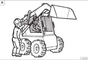
In addition to the design and configuration of equipment, hazard control and accident prevention are dependent upon the awareness, concern, prudence and proper training of personnel involved in the operation, transport, maintenance and storage of equipment.
Check that the Bob-Tach levers are in the locked position and the wedges are fully engaged into the mounting holes of the attachment (if applicable).
- Check that the implement is securely fastened to the machine.
- Operate the attachment / implement according to the Operation & Maintenance Manual.
- When learning to operate the attachment / implement, do it at a slow rate in an area clear of bystanders.
- DO NOT permit personnel to be in the work area when operating the machine and attachment / implement.
- The attachment / implement must be used ONLY on approved machines. See your Bobcat dealer for updated list of approved attachments / implements for each machine model. •
- O NOT modify equipment or add attachments / implements that exceed manufacturer’s specifications.
- DO NOT make any adjustments or repairs on the machine or attachment / implement while the engine is running.
- • Keep shields and guards in place. Replace if damaged.
- The dealer and owner / operator review the recommended uses of the product when delivered. If the owner / operator will be using the machine for a different application(s) he or she must ask the dealer for recommendations on the new use.
IMAGES PREVIEW OF THE MANUAL:
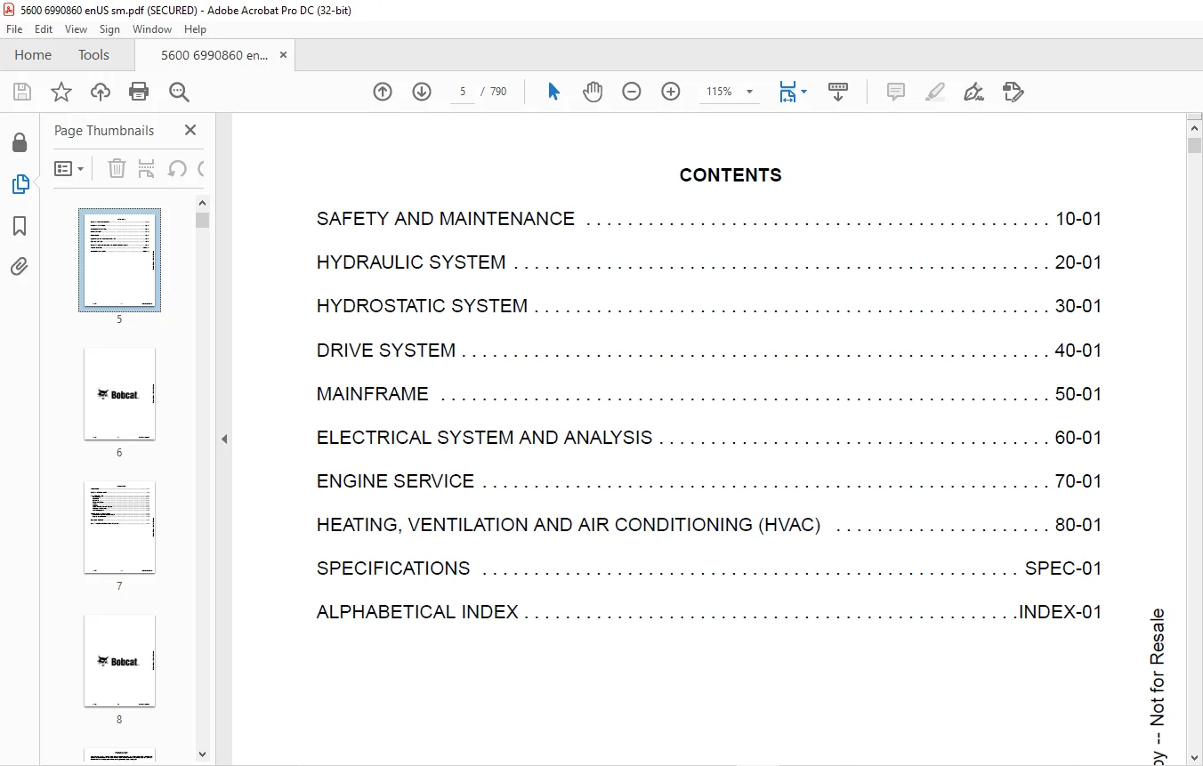
TABLE OF CONTENTS:
Bobcat Toolcat™ 5600 Utility Work Machine Service Manual SN AHG811001 & Above – PDF DOWNLOAD
MAINTENANCE SAFETY....................................................................  3
CONTENTS..............................................................................  5
FOREWORD..............................................................................  7
	FOREWORD..........................................................................  9
	SAFETY INSTRUCTIONS............................................................... 11
	FIRE PREVENTION................................................................... 13
		Maintenance................................................................... 13
		Operation..................................................................... 13
		Electrical.................................................................... 13
		Hydraulic System.............................................................. 13
		Fueling....................................................................... 13
		Starting...................................................................... 13
		Spark Arrester Exhaust System................................................. 13
		Welding And Grinding.......................................................... 14
		Fire Extinguishers............................................................ 14
	SERIAL NUMBER LOCATIONS........................................................... 15
		Utility Work Machine Serial Number............................................ 15
		Engine Serial Number.......................................................... 15
	DELIVERY REPORT................................................................... 16
	UTILITY WORK MACHINE IDENTIFICATION............................................... 17
SAFETY AND MAINTENANCE................................................................ 19
	LIFTING AND BLOCKING THE UTILITY WORK MACHINE..................................... 23
		Procedure For Jackstand Placement On The Control Arms......................... 23
		Procedure For Jackstand Placement On The Frame................................ 24
	LIFT ARM SUPPORT DEVICE........................................................... 25
		Installing.................................................................... 25
		Removing...................................................................... 26
	CARGO BOX SUPPORT DEVICE.......................................................... 27
		Installing.................................................................... 27
		Removing...................................................................... 28
		Raising The Cargo Box When Engine Is Not Running.............................. 28
	OPERATOR CAB...................................................................... 29
		Description................................................................... 29
	TRANSPORTING THE UTILITY WORK MACHINE ON A TRAILER................................ 31
		Loading And Unloading......................................................... 31
		Fastening..................................................................... 32
	TOWING THE UTILITY WORK MACHINE................................................... 33
		Procedure..................................................................... 33
	REMOTE START TOOL KIT - MEL1563................................................... 35
		Remote Start Tool - MEL1563................................................... 35
		Service Tool Harness Control - MEL1565........................................ 36
		Service Tool Harness Communicator - MEL1566................................... 37
		Remote Start Procedure........................................................ 38
	REMOTE START TOOL (SERVICE TOOL) KIT - 7217666.................................... 41
		Description................................................................... 41
		Remote Start Tool (Service Tool) - 7022042.................................... 42
		Service Tool Harness - 6689747................................................ 43
		Computer Service Tool Harness - 6689746....................................... 44
		Remote Start Procedure........................................................ 45
	SERVICE SCHEDULE.................................................................. 49
		Maintenance Intervals......................................................... 49
	AIR CLEANER SERVICE............................................................... 51
		Replacing Filter Elements..................................................... 51
	ENGINE COOLING SYSTEM............................................................. 53
		Checking Level................................................................ 53
		Cleaning...................................................................... 54
		Removing And Replacing Coolant................................................ 54
	FUEL SYSTEM....................................................................... 57
		Fuel Specifications........................................................... 57
		Biodiesel Blend Fuel.......................................................... 57
		Filling The Fuel Tank......................................................... 58
		Fuel Filter................................................................... 58
		Removing Air From The Fuel System............................................. 59
		Filling A Portable Fuel Container............................................. 60
	ENGINE LUBRICATION SYSTEM......................................................... 61
		Checking And Adding Engine Oil................................................ 61
		Engine Oil Chart.............................................................. 61
		Removing And Replacing Oil And Filter......................................... 62
	HYDRAULIC / HYDROSTATIC SYSTEM.................................................... 63
		Checking Fluid................................................................ 63
		Hydraulic / Hydrostatic Fluid Chart........................................... 63
		Adding Fluid.................................................................. 64
		Alternate Fill Procedure...................................................... 64
		Removing And Replacing Hydraulic / Hydrostatic And Case Drain Filters......... 65
		Removing And Replacing Hydraulic Fluid........................................ 67
		Breather Cap.................................................................. 68
	TRANSAXLE (FRONT AND REAR)........................................................ 69
		Checking And Adding Lubricant................................................. 69
		Removing And Replacing Lubricant.............................................. 70
	BOB-TACH (HAND LEVER)............................................................. 71
		Inspection And Maintenance.................................................... 71
	BOB-TACH (POWER).................................................................. 73
		Inspection And Maintenance.................................................... 73
	LUBRICATING THE UTILITY WORK MACHINE.............................................. 75
		Lubrication Locations......................................................... 75
	TIRE MAINTENANCE.................................................................. 77
		Wheel Nuts.................................................................... 77
		Rotating...................................................................... 77
		Mounting...................................................................... 78
	PIVOT PINS........................................................................ 79
		Inspection And Maintenance.................................................... 79
	UTILITY WORK MACHINE STORAGE AND RETURN TO SERVICE................................ 81
		Storage....................................................................... 81
		Return To Service............................................................. 81
	STOPPING THE ENGINE AND LEAVING THE UTILITY WORK MACHINE.......................... 83
		Procedure..................................................................... 83
		Emergency Exit (When Equipped With Cab)....................................... 83
	SEAT BELT......................................................................... 85
		Inspection And Maintenance.................................................... 85
HYDRAULIC SYSTEM...................................................................... 87
	HYDRAULIC / HYDROSTATIC SCHEMATICS................................................ 91
	HYDRAULIC SYSTEM INFORMATION...................................................... 95
		Glossary Of Hydraulic / Hydrostatic Symbols................................... 95
		Troubleshooting............................................................... 99
	CYLINDER (LIFT)...................................................................101
		Testing.......................................................................101
		Removal And Installation......................................................102
		Parts Identification..........................................................105
		Disassembly...................................................................106
		Assembly......................................................................108
	CYLINDER (TILT)...................................................................111
		Testing.......................................................................111
		Removal And Installation......................................................112
		Parts Identification..........................................................114
		Disassembly...................................................................115
		Assembly......................................................................117
	CYLINDER (CARGO BOX)..............................................................119
		Testing.......................................................................119
		Removal And Installation (Left Side)..........................................120
		Removal And Installation (Right Side).........................................122
		Parts Identification..........................................................123
		Disassembly...................................................................124
		Assembly......................................................................126
	CYLINDER (STEERING)...............................................................129
		Testing (Rear)................................................................129
		Testing (Front)...............................................................130
		Removal And Installation (Rear)...............................................131
		Removal And Installation (Front)..............................................134
		Parts Identification..........................................................137
		Disassembly And Assembly......................................................138
	CYLINDER (BOB-TACH)...............................................................143
		Testing.......................................................................143
		Removal And Installation......................................................144
		Parts Identification..........................................................145
		Disassembly...................................................................146
		Assembly......................................................................148
	VALVE (MAIN RELIEF)...............................................................151
		Description...................................................................151
		Auxiliary Main Relief Valve Testing...........................................151
		Auxiliary Main Relief Valve Removal And Installation..........................152
		Lift, Tilt And Cargo Box Main Relief Valve Testing............................153
		Lift, Tilt And Cargo Box Main Relief Valve Removal And Installation...........154
	VALVE (PORT RELIEF)...............................................................155
		Description...................................................................155
		Lift Port Relief Valve Testing (Base End).....................................155
		Lift Port Relief Valve Testing (Rod End)......................................156
		Tilt Port Relief Valve Testing................................................157
	HYDRAULIC CONTROL VALVE...........................................................159
		Description...................................................................159
		Removal And Installation......................................................159
		Identification Chart..........................................................162
		Disassembly...................................................................163
		End Valve Section Disassembly And Assembly....................................166
		Box Valve Section Disassembly And Assembly....................................168
		Lift Valve Section Disassembly And Assembly...................................172
		Tilt Valve Section Disassembly And Assembly...................................177
		Mid Inlet / High Flow Valve Section Disassembly And Assembly..................181
		Auxiliary Valve Section Disassembly And Assembly..............................185
		Assembly......................................................................190
	STEERING SELECTOR VALVE...........................................................195
		Description...................................................................195
		Removal And Installation......................................................195
		Disassembly And Assembly......................................................197
	PILOT MANIFOLD (WITHOUT TRACTION CONTROL).........................................199
		Description...................................................................199
		Removal And Installation......................................................199
		Parts Identification..........................................................201
		Disassembly And Assembly......................................................202
	PILOT MANIFOLD (WITH TRACTION CONTROL)............................................207
		Description...................................................................207
		Removal And Installation......................................................207
		Parts Identification..........................................................209
		Disassembly And Assembly......................................................210
	LIFT ARM (BYPASS).................................................................215
		Description...................................................................215
		Testing.......................................................................215
	HYDRAULIC PUMP....................................................................217
		Description...................................................................217
		Auxiliary Section Testing.....................................................218
		Lift, Tilt And Cargo Box Section Testing......................................220
		Steering And Cooling Fan Section Testing......................................222
		Removal And Installation......................................................224
		Parts Identification..........................................................227
		Disassembly And Assembly......................................................228
	POWER STEERING PUMP...............................................................237
		Description...................................................................237
		Removal And Installation......................................................237
		Disassembly And Assembly......................................................238
	HYDRAULIC / HYDROSTATIC FILTER....................................................243
		Description...................................................................243
		Housing Removal And Installation..............................................243
		Case Drain Housing Removal And Installation...................................244
	CONTROL JOYSTICK..................................................................245
		Description...................................................................245
		Handle Removal And Installation...............................................245
	HYDRAULIC FLUID RESERVOIR.........................................................247
		Description...................................................................247
		Removal And Installation......................................................247
		Hydraulic Fluid Screen........................................................250
	OIL COOLER / RADIATOR.............................................................251
		Description...................................................................251
		Removal And Installation......................................................251
	AUXILIARY HYDRAULIC COUPLER BLOCK.................................................253
		Description...................................................................253
		Removal And Installation......................................................254
		Disassembly And Assembly (FFI/FI).............................................255
		Disassembly And Assembly (FFH/FH).............................................257
	REMOTE HYDRAULICS DIVERTER VALVE..................................................259
		Description...................................................................259
		Removal And Installation......................................................259
		Disassembly And Assembly......................................................260
	POWER BOB-TACH BLOCK..............................................................261
		Description...................................................................261
		Removal And Installation......................................................261
		Disassembly And Assembly......................................................263
	DIVERTER VALVE (REAR AUXILIARY)...................................................269
		Description...................................................................269
		Solenoid Testing..............................................................269
		Removal And Installation......................................................270
		Disassembly And Assembly......................................................272
HYDROSTATIC SYSTEM....................................................................281
	HYDROSTATIC SYSTEM INFORMATION....................................................283
		Troubleshooting...............................................................283
		Description...................................................................284
	HYDROSTATIC MOTOR.................................................................285
		Description...................................................................285
		Removal And Installation (Front)..............................................285
		Removal And Installation (Rear)...............................................289
		Parts Identification..........................................................292
		Disassembly...................................................................293
		Assembly......................................................................303
	CHARGE PRESSURE...................................................................309
		Description...................................................................309
		Testing.......................................................................309
	HYDROSTATIC PUMP..................................................................311
		Description...................................................................311
		Removal And Installation......................................................311
		Control Module Removal And Installation.......................................314
		Replenishing / High Pressure Relief Valve Removal And Installation............316
		Charge Relief Valve Removal And Installation..................................316
		Parts Identification..........................................................317
		Disassembly And Assembly......................................................319
		Mechanical Neutral Adjustment.................................................333
		Hydraulic Controller Neutral Adjustment.......................................338
	DRIVE BELT........................................................................343
		Description...................................................................343
		Exhaust Tube Removal And Installation.........................................343
		Shield Removal And Installation...............................................344
		Belt Adjusting................................................................345
		Belt Replacement..............................................................346
		Tensioner Pulley Removal And Installation.....................................347
		Tensioner Pulley Disassembly..................................................348
DRIVE SYSTEM..........................................................................349
	BRAKE.............................................................................351
		Description...................................................................351
		Disassembly And Assembly (Front Transaxle)....................................351
		Disassembly And Assembly (Rear Transaxle).....................................352
	TRANSAXLE.........................................................................353
		Description...................................................................353
		Removal And Installation (Front)..............................................353
		Removal And Installation (Rear)...............................................357
		Brake Housing Disassembly And Assembly........................................361
		Primary Housing Disassembly And Assembly......................................364
	HUB...............................................................................371
		Description...................................................................371
		Removal And Installation......................................................371
	CV SHAFT..........................................................................373
		Description...................................................................373
		Removal And Installation (Front)..............................................373
		Removal And Installation (Rear)...............................................376
		Inner Boot Removal And Installation...........................................379
		Outer Boot Removal And Installation...........................................381
MAINFRAME.............................................................................385
	OPERATOR CAB......................................................................387
		Removal And Installation......................................................387
	OPERATOR SEAT.....................................................................397
		Removal And Installation......................................................397
		Seat Belt Removal And Installation............................................398
		Seat Pan Removal And Installation.............................................399
		Slide Rail Removal And Installation...........................................399
		Armrest Bracket Removal And Installation......................................400
		Armrest Removal And Installation..............................................400
	PASSENGER SEAT....................................................................401
		Removal And Installation......................................................401
		Seat Belt Removal And Installation............................................402
		Seat Pan Removal And Installation.............................................403
		Armrest Removal And Installation..............................................403
	BOB-TACH (HAND LEVER).............................................................405
		Description...................................................................405
		Removal And Installation......................................................405
		Lever And Wedge Disassembly And Assembly......................................406
	BOB-TACH (POWER)..................................................................409
		Description...................................................................409
		Removal And Installation......................................................409
		Lever And Wedge Disassembly And Assembly......................................411
	LIFT ARM..........................................................................413
		Removal And Installation......................................................413
	CARGO BOX.........................................................................415
		Removal And Installation......................................................415
	STEERING COLUMN...................................................................417
		Removal And Installation......................................................417
	FUEL TANK.........................................................................419
		Removal And Installation......................................................419
		Fuel Level Sender Removal And Installation....................................421
	DRIVE AND BRAKE PEDALS............................................................423
		Description...................................................................423
		Removal And Installation......................................................423
		Drive Pedal Disassembly And Assembly..........................................424
	SHOCKS............................................................................425
		Removal And Installation......................................................425
	CONTROL ARMS......................................................................427
		Removal And Installation (Lower Arm)..........................................427
		Removal And Installation (Upper Arm)..........................................428
		Inspection....................................................................429
		Ball Joint Removal And Installation...........................................430
	SPINDLE...........................................................................431
		Removal And Installation......................................................431
	TIE ROD...........................................................................433
		Description...................................................................433
		Removal And Installation......................................................433
		Toe Adjustment Procedure......................................................434
	FLOOR CONSOLE.....................................................................437
		Access Cover Removal And Installation (Side)..................................437
		Access Cover Removal And Installation (Top)...................................437
	CENTER CONSOLE....................................................................439
		Removal And Installation......................................................439
	FENDER............................................................................443
		Removal And Installation (Front)..............................................443
		Removal And Installation (Left Rear)..........................................444
		Removal And Installation (Right Rear).........................................445
	WINDOWS...........................................................................447
		Front, Rear And Lower Door Removal And Installation...........................447
		Upper Door Removal And Installation...........................................450
	HEADLINER.........................................................................453
		Removal And Installation......................................................453
ELECTRICAL SYSTEM AND ANALYSIS........................................................457
	ELECTRICAL SCHEMATICS.............................................................461
	ELECTRICAL SYSTEM INFORMATION.....................................................475
		Glossary Of Electrical Symbols................................................475
		Cab Harness Connectors........................................................478
		Mainframe Harness Connectors..................................................479
		Engine Harness Connectors.....................................................480
		Description...................................................................481
		Troubleshooting...............................................................482
		Fuse And Relay Location - Cab Panel...........................................483
		Fuse And Relay Location - Frame Panel.........................................484
		Solenoid Testing..............................................................485
	BATTERY...........................................................................487
		Removal And Installation......................................................487
		Servicing.....................................................................489
		Using A Booster Battery (Jump Starting).......................................490
	ALTERNATOR........................................................................491
		Belt Adjustment...............................................................491
		Belt Replacement..............................................................491
		Charging System Inspection....................................................492
		Alternator Voltage Testing....................................................493
		Low Voltage Testing...........................................................494
		High Voltage Testing..........................................................494
		Removal And Installation......................................................495
		Parts Identification..........................................................497
	STARTER...........................................................................499
		Testing.......................................................................499
		Removal And Installation......................................................500
		Parts Identification..........................................................501
	INSTRUMENT PANELS.................................................................503
		Display Controller Panel......................................................503
		Switch Panel..................................................................504
		Floor Console.................................................................505
		Center Console................................................................506
		Radio.........................................................................507
	LIGHTS............................................................................509
		Front Removal And Installation................................................509
	BOBCAT CONTROLLER (DISPLAY).......................................................511
		Description...................................................................511
		Connector Identification......................................................512
		Removal And Installation......................................................513
	BOBCAT CONTROLLER (DRIVE).........................................................515
		Description...................................................................515
		Connector Identification......................................................516
		Removal And Installation......................................................517
	ENGINE CONTROL UNIT (ECU).........................................................519
		Description...................................................................519
		Cleaning......................................................................520
		Removal And Installation......................................................521
	DIAGNOSTIC SERVICE CODES..........................................................523
		Description...................................................................523
		Service Codes List............................................................524
	CONTROL PANEL SETUP...............................................................529
		Enter Setup...................................................................529
		Two-Speed.....................................................................529
		High Flow.....................................................................529
		Horsepower Management.........................................................529
		Tire Size.....................................................................529
		Save Setup....................................................................529
		Exit Setup....................................................................529
	PASSWORD SETUP (KEYLESS START)....................................................531
		Password Description..........................................................531
		Changing The Owner And Operator Passwords.....................................531
		Password Lockout Feature......................................................532
	TOOLCAT INTERLOCK CONTROL SYSTEM (TICS™)..........................................533
		Description...................................................................533
		Inspecting The TICS™..........................................................533
		Maintaining The TICS™.........................................................533
		Lift Arm Bypass Procedure.....................................................534
		Inspecting....................................................................534
	ARMREST SENSOR....................................................................535
		Description...................................................................535
		Removal And Installation......................................................535
	SPEED SENSORS.....................................................................537
		Description...................................................................537
		Removal And Installation (Front Transaxle)....................................537
	WHEEL POSITION SENSORS............................................................539
		Description...................................................................539
		Removal And Installation (Front)..............................................539
		Removal And Installation (Rear)...............................................540
		Adjusting (In The Machine)....................................................541
		Adjusting (Out Of The Machine)................................................542
	SERVICE PC (LAPTOP COMPUTER)......................................................543
		Connecting Remote Start Tool..................................................543
		Connecting Remote Start Tool (Service Tool)...................................543
	CALIBRATION.......................................................................545
		Description...................................................................545
		Throttle Position Sensor Calibration..........................................545
		Drive System Calibration......................................................546
		Brake Pedal Calibration.......................................................547
		Travel Pedal Calibration......................................................548
	TRAVEL DIRECTION CONTROL LEVER....................................................549
		Description...................................................................549
		Removal And Installation......................................................549
	ELECTRIC COOLING FAN..............................................................551
		Description...................................................................551
		Removal And Installation......................................................551
	MAINTENANCE CLOCK.................................................................553
		Description...................................................................553
		Setup.........................................................................553
		Reset.........................................................................555
	BACK-UP ALARM SYSTEM..............................................................557
		Description...................................................................557
		Inspecting....................................................................557
	FRONT HORN........................................................................559
		Description...................................................................559
		Removal And Installation......................................................559
		Troubleshooting...............................................................560
	TRACTION CONTROL..................................................................561
		Description...................................................................561
		Operation.....................................................................561
		Removal And Installation......................................................562
	ELECTRICAL / HYDRAULIC CONTROLS...................................................565
		Description...................................................................565
		Identification Chart ACD Group 0..............................................566
		Identification Chart ACD Group 1..............................................566
		Identification Chart ACD Group 2..............................................567
		Identification Chart ACD Group 3..............................................567
ENGINE SERVICE........................................................................569
	ENGINE INFORMATION................................................................573
		Description...................................................................573
		Specifications................................................................574
		Sensor Location...............................................................576
		Torque Values.................................................................582
		Troubleshooting...............................................................584
		Engine Removal And Installation...............................................586
		Engine Mount Replacement......................................................592
		Compression - Testing.........................................................593
		Injector Signal - Testing.....................................................595
		Injector Signal - Testing (In-Line)...........................................597
	ENGINE SPEED CONTROL..............................................................599
		Removal And Installation......................................................599
		Disassembly And Assembly......................................................599
	DIESEL OXIDATION CATALYST (DOC)...................................................601
		Removal And Installation......................................................601
	AIR CLEANER.......................................................................603
		Housing Removal And Installation..............................................603
	ENGINE COOLING SYSTEM.............................................................605
		Radiator / Oil Cooler Removal And Installation................................605
		Hydraulic Fan Description.....................................................608
		Hydraulic Fan Removal And Installation........................................608
		Hydraulic Fan Disassembly And Assembly........................................611
		Water Pump Removal And Installation...........................................614
		Thermostat Housing Removal And Installation...................................615
		Testing The Thermostat........................................................616
	LUBRICATION SYSTEM................................................................617
		Description...................................................................617
		Oil Pan Removal And Installation..............................................618
		Oil Pump Removal And Installation.............................................619
		Oil Pump Relief Valve Description.............................................620
		Oil Pump Relief Valve Removal And Installation................................620
		Oil Cooler Removal And Installation...........................................621
		Oil Filter Head Removal And Installation......................................622
		Oil Cooler Bypass Description.................................................623
		Oil Cooler Bypass Removal And Installation....................................623
	FUEL SYSTEM.......................................................................625
		Description...................................................................625
		High Pressure Pump Removal And Installation...................................626
		Fuel Temperature Sensor Removal And Installation..............................629
		Fuel Cooler Removal And Installation..........................................630
		Fuel Cooler Bypass Valve Removal And Installation.............................630
		Fuel Recirculation Valve Removal And Installation.............................631
		Fuel Rail Assembly Removal And Installation...................................632
		Fuel Injector Removal And Installation........................................634
		Removing Air From The Fuel System.............................................636
	CYLINDER HEAD.....................................................................639
		Glow Plugs Testing............................................................639
		Glow Plugs Removal And Installation...........................................640
		Valve Clearance Adjustment....................................................641
		Cylinder Head Removal And Installation........................................643
		Cylinder Head Disassembly And Assembly........................................646
		Cylinder Head Inspection......................................................648
		Cylinder Head Top Clearance...................................................649
		Valve Step Height.............................................................650
		Valve Stem Height.............................................................650
		Valve Guide...................................................................651
		Valve.........................................................................651
		Valve Spring..................................................................652
		Rocker Arm Shaft Disassembly And Assembly.....................................653
		Rocker Arm Shaft Inspection...................................................654
		Push Rod Inspection...........................................................654
	CRANKSHAFT AND PISTONS............................................................655
		Piston And Connecting Rod Removal And Installation............................655
		Piston And Connecting Rod Inspection..........................................656
		Crankshaft Removal And Installation...........................................658
		Cylinder Block Inspection.....................................................661
		Crankshaft Inspection.........................................................663
		Engine Component Class........................................................664
	CAMSHAFT..........................................................................667
		Removal And Installation......................................................667
		Inspecting....................................................................668
	GEARCASE..........................................................................671
		Gearcase Cover Removal And Installation.......................................671
		Gear Backlash.................................................................672
		Gear Timing...................................................................673
		Idle Gear Removal And Installation............................................674
	TURBOCHARGER......................................................................675
		Description...................................................................675
		Removal And Installation......................................................675
		Inspection....................................................................678
	FLYWHEEL AND HOUSING..............................................................681
		Flywheel Removal And Installation.............................................681
		Ring Gear Removal And Installation............................................682
		Housing Removal And Installation..............................................682
	EXHAUST GAS RECIRCULATION (EGR) SYSTEM............................................687
		Description...................................................................687
		Removal And Installation......................................................688
		Disassembly And Assembly......................................................690
HEATING, VENTILATION AND AIR CONDITIONING (HVAC)......................................693
	AIR CONDITIONING SYSTEM FLOW......................................................695
		Description...................................................................695
		A/C System Diagram............................................................696
		Components....................................................................697
		Safety Equipment..............................................................700
	REGULAR MAINTENANCE...............................................................701
		Filter Elements Removal And Installation......................................701
		Compressor Drive Belt Inspection..............................................702
		Condenser.....................................................................702
		Air Conditioning Service Chart................................................703
		A/C Evaporator Coil...........................................................704
	TROUBLESHOOTING...................................................................705
		Blower Motor Does Not Operate.................................................705
		Blower Motor Operates Normally But Air Flow Is Insufficient...................705
		Insufficient Cooling Although Air Flow And Compressor Operation Are Normal....705
		The Compressor Does Not Operate At All Or Operates Improperly.................706
		Gauge Pressure Related Troubleshooting........................................707
		Temperature / Pressure Chart..................................................709
		Poor A/C Performance..........................................................710
		HVAC Repair And Leaks.........................................................710
		Electrical System.............................................................711
		Engine Coolant Bypassing The Heater Valve.....................................720
		Heater Valve Not Opening Or Closing...........................................721
	SYSTEM CHARGING AND RECLAMATION...................................................723
		Refrigerant Identification....................................................723
		Reclamation And Charging With Recovery / Charging Unit........................724
		Charging With A Manifold Gauge Set............................................726
	COMPRESSOR........................................................................729
		Belt Adjustment...............................................................729
		Belt Replacement..............................................................729
		Removal And Installation......................................................730
		Oil...........................................................................731
		Oil Check.....................................................................732
	CONDENSER.........................................................................733
		Removal And Installation......................................................733
	RECEIVER / DRIER..................................................................735
		Receiver / Drier Removal And Installation.....................................735
		Pressure Relief Valve Removal And Installation................................736
		Pressure Switch Removal And Installation......................................737
	EVAPORATOR / HEATER UNIT..........................................................739
		Removal And Installation......................................................739
	THERMOSTAT........................................................................743
		Description...................................................................743
		Removal And Installation......................................................744
	EXPANSION VALVE...................................................................747
		Removal And Installation......................................................747
	EVAPORATOR COIL...................................................................749
		Removal And Installation......................................................749
	HEATER COIL.......................................................................751
		Removal And Installation With A/C.............................................751
	BLOWER FAN........................................................................753
		Removal And Installation......................................................753
	HEATER VALVE......................................................................755
		Removal And Installation......................................................755
		Disassembly And Assembly......................................................755
SPECIFICATIONS........................................................................757
	(5600) UTILITY WORK MACHINE SPECIFICATIONS........................................759
		Dimensions (With 27 Inch Tires)...............................................759
		Dimensions (With 29 Inch Tires)...............................................760
		Performance...................................................................761
		Controls......................................................................761
		Engine........................................................................761
		Hydraulic System..............................................................762
		Electrical....................................................................762
		Drive System..................................................................763
		Capacities....................................................................763
		Tires.........................................................................763
	TECHNICAL SERVICE GUIDE SPECIFICATIONS............................................765
		Engine........................................................................765
		Engine Torques................................................................765
		Cooling System................................................................765
		Loader Torques................................................................766
		Hydraulic / Hydrostatic System................................................766
		Fuel Consumption..............................................................766
	TORQUE SPECIFICATIONS FOR BOLTS...................................................767
		Torque For General SAE Bolts..................................................767
		Torque For General Metric Bolts...............................................768
	HYDRAULIC CONNECTION SPECIFICATIONS...............................................769
		O-ring Face Seal Connection...................................................769
		Straight Thread O-ring Fitting................................................770
		Tubelines And Hoses...........................................................770
		Flare Fitting.................................................................770
		O-ring Flare Fitting..........................................................771
		Port Seal Fitting.............................................................773
		Quick-Lok™ Fitting............................................................774
	HYDRAULIC / HYDROSTATIC FLUID SPECIFICATIONS......................................775
		Specifications................................................................775
	CONVERSIONS.......................................................................777
		Decimal And Millimeter Equivalent Chart.......................................777
		U.S. To Metric Conversion Chart...............................................778
	SERVICE TOOLS REQUIRED............................................................779
		Remote Start Tools............................................................779
		Hydraulic Tools...............................................................780
		Mainframe And Drive Tools.....................................................782
		Electrical Tools..............................................................782
		Engine Tools..................................................................783
		HVAC Tools....................................................................786
ALPHABETICAL INDEX....................................................................787
Contact us: [email protected]
https://vimeo.com/846519487?share=copy
PLEASE NOTE:
- This is the same manual used by the dealers to diagnose and troubleshoot your vehicle
- You will be directed to the download page as soon as the purchase is completed. The whole payment and downloading process will take anywhere between 2-5 minutes
- Need any other service / repair / parts manual, please feel free to contact [email protected] . We still have 50,000 manuals unlisted
s.m