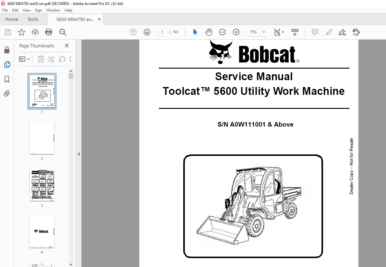
Bobcat Toolcat™ 5600 Utility Work Machine Service Manual SNA0W111001 & Above – PDF DOWNLOAD
$32.95
Bobcat Toolcat™ 5600 Utility Work Machine Service Manual SNA0W111001 & Above – PDF DOWNLOAD
Description
Bobcat Toolcat™ 5600 Utility Work Machine Service Manual SNA0W111001 & Above – PDF DOWNLOAD
FILE DETAILS:
Bobcat Toolcat™ 5600 Utility Work Machine Service Manual SNA0W111001 & Above – PDF DOWNLOAD
Language : English
Pages : 741
Downloadable : Yes
File Type : PDF
DESCRIPTION:
Bobcat Toolcat™ 5600 Utility Work Machine Service Manual SNA0W111001 & Above – PDF DOWNLOAD
FOREWORD
This manual is for the Toolcat Utility Work Machine mechanic. It provides necessary servicing and adjustment procedures for the Toolcat Utility Work Machine and its component parts and systems. Refer to the for operating instructions, starting procedure, daily checks, etc.
SAFETY INSTRUCTIONS
Instructions are necessary before operating or servicing machine. Read and understand the Operation & Maintenance Manual, Operator’s Handbook and signs (decals) on machine. Follow warnings and instructions in the manuals when making repairs, adjustments or servicing. Check for correct function after adjustments, repairs or service. Untrained operators and failure to follow instructions can cause injury or death
The following publications provide information on the safe use and maintenance of the Bobcat machine and attachments:
- The Delivery Report is used to assure that complete instructions have been given to the new owner and that the machine is in safe operating condition.
- The Operation & Maintenance Manual delivered with the machine or attachment contains operating information as well as routine maintenance and service procedures. It is a part of the machine and can be stored in a container provided on the machine. Replacement Operation & Maintenance Manuals can be ordered from your Bobcat dealer.
- Machine signs (decals) instruct on the safe operation and care of your Bobcat machine or attachment. The signs and their locations are shown in the Operation & Maintenance Manual. Replacement signs are available from your Bobcat dealer.
- An Operator’s Handbook fastened to the operator cab. It’s brief instructions are convenient to the operator. The handbook is available from your dealer in an English edition or one of many other languages. See your Bobcat dealer for more information on translated versions.
- The Service Manual and Parts Manual are available from your dealer for use by mechanics to do shoptype service and repair work.
- The Utility Work Machine Operator Training Course is available through your local dealer or at www.training.bobcat.com or www.bobcat.com. This course is intended to provide rules and practices of correct operation of the Utility Work Machine. The course is available in English and Spanish versions
IMAGES PREVIEW OF THE MANUAL:
TABLE OF CONTENTS:
Bobcat Toolcat™ 5600 Utility Work Machine Service Manual SNA0W111001 & Above – PDF DOWNLOAD
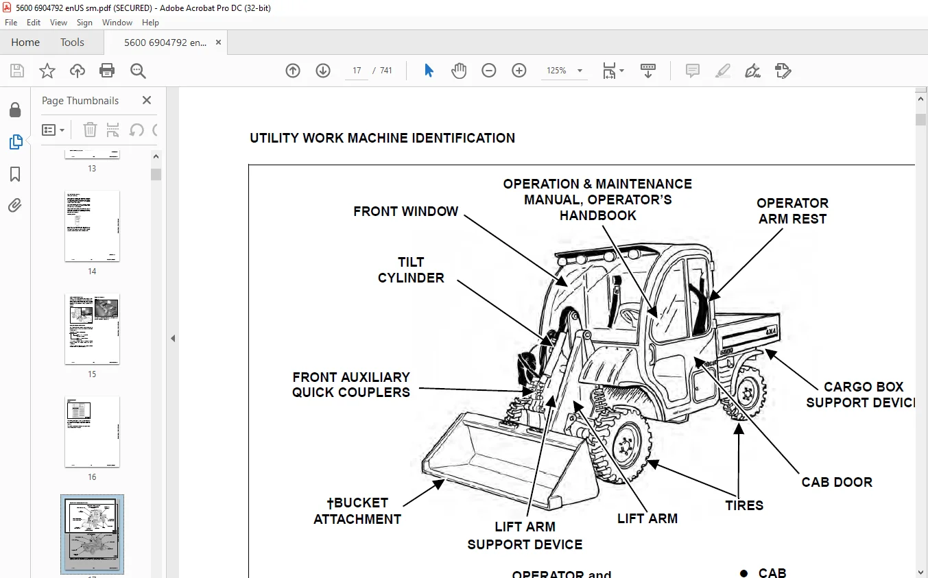
MAINTENANCE SAFETY....................................................................  3
CONTENTS..............................................................................  5
FOREWORD..............................................................................  7
	FOREWORD..........................................................................  9
	SAFETY INSTRUCTIONS............................................................... 11
	FIRE PREVENTION................................................................... 13
		Maintenance................................................................... 13
		Operation..................................................................... 13
		Electrical.................................................................... 13
		Hydraulic System.............................................................. 13
		Fueling....................................................................... 13
		Starting...................................................................... 13
		Spark Arrester Exhaust System................................................. 13
		Welding And Grinding.......................................................... 14
		Fire Extinguishers............................................................ 14
	SERIAL NUMBER LOCATIONS........................................................... 15
		Utility Work Machine Serial Number............................................ 15
		Engine Serial Number.......................................................... 15
	DELIVERY REPORT................................................................... 16
	UTILITY WORK MACHINE IDENTIFICATION............................................... 17
SAFETY & MAINTENANCE.................................................................. 19
	LIFTING AND BLOCKING THE UTILITY WORK MACHINE..................................... 23
		Procedure For Jackstand Placement On The Control Arms......................... 23
		Procedure For Jackstand Placement On The Frame................................ 24
	LIFT ARM SUPPORT DEVICE........................................................... 25
		Installing.................................................................... 25
		Removing...................................................................... 25
	CARGO BOX SUPPORT DEVICE.......................................................... 27
		Installing.................................................................... 27
		Removing...................................................................... 27
		Raising The Cargo Box When Engine Is Not Running.............................. 28
	OPERATOR CAB...................................................................... 29
		Description................................................................... 29
	TRANSPORTING THE UTILITY WORK MACHINE ON A TRAILER................................ 31
		Loading And Unloading......................................................... 31
		Fastening..................................................................... 31
	TOWING THE UTILITY WORK MACHINE................................................... 33
		Procedure..................................................................... 33
	REMOTE START TOOL KIT - MEL1563................................................... 35
		Remote Start Tool - MEL1563................................................... 35
		Service Tool Harness Control - MEL1565........................................ 36
		Service Tool Harness Communicator - MEL1566................................... 37
		Remote Start Procedure........................................................ 38
	REMOTE START TOOL (SERVICE TOOL) KIT - 6689779.................................... 41
		Description................................................................... 41
		Remote Start Tool (Service Tool) - 6689778.................................... 42
		Service Tool Harness - 6689747................................................ 43
		Computer Service Tool Harness - 6689746....................................... 44
		Remote Start Procedure........................................................ 45
	SERVICE SCHEDULE.................................................................. 49
		Chart......................................................................... 49
	AIR CLEANER SERVICE............................................................... 51
		Replacing Filter Elements..................................................... 51
	ENGINE COOLING SYSTEM............................................................. 53
		Checking Level................................................................ 53
		Cleaning...................................................................... 54
		Removing And Replacing Coolant................................................ 54
	FUEL SYSTEM....................................................................... 55
		Fuel Specifications........................................................... 55
		Biodiesel Blend Fuel.......................................................... 55
		Filling The Fuel Tank......................................................... 56
		Fuel Filter................................................................... 56
		Removing Air From The Fuel System............................................. 57
		Filling A Portable Fuel Container............................................. 57
	ENGINE LUBRICATION SYSTEM......................................................... 59
		Checking And Adding Engine Oil................................................ 59
		Engine Oil Chart.............................................................. 59
		Removing And Replacing Oil And Filter......................................... 60
	HYDRAULIC / HYDROSTATIC SYSTEM.................................................... 61
		Checking Fluid................................................................ 61
		Hydraulic / Hydrostatic Fluid Chart........................................... 61
		Adding Fluid.................................................................. 61
		Alternate Fill Procedure...................................................... 62
		Removing And Replacing Hydraulic / Hydrostatic And Case Drain Filters......... 63
		Removing And Replacing Hydraulic Fluid........................................ 64
		Breather Cap.................................................................. 66
	TRANS AXLE (FRONT AND REAR)....................................................... 67
		Checking And Adding Lubricant................................................. 67
		Removing And Replacing Lubricant.............................................. 68
	BOB-TACH (HAND LEVER)............................................................. 69
		Inspection And Maintenance.................................................... 69
	BOB-TACH (POWER).................................................................. 71
		Inspection And Maintenance.................................................... 71
	LUBRICATING THE UTILITY WORK MACHINE.............................................. 73
		Lubrication Locations......................................................... 73
	TIRE MAINTENANCE.................................................................. 75
		Wheel Nuts.................................................................... 75
		Rotating...................................................................... 75
		Mounting...................................................................... 75
	SPARK ARRESTER MUFFLER............................................................ 77
		Cleaning Procedure............................................................ 77
	PIVOT PINS........................................................................ 79
		Inspection And Maintenance.................................................... 79
	UTILITY WORK MACHINE STORAGE AND RETURN TO SERVICE................................ 81
		Storage....................................................................... 81
		Return To Service............................................................. 81
	STOPPING THE ENGINE AND LEAVING THE UTILITY WORK MACHINE.......................... 83
		Procedure..................................................................... 83
		Emergency Exit (When Equipped With Cab)....................................... 83
	SEAT BELT......................................................................... 85
		Inspection And Maintenance.................................................... 85
HYDRAULIC SYSTEM...................................................................... 87
	HYDRAULIC / HYDROSTATIC SCHEMATICS................................................ 91
	HYDRAULIC SYSTEM INFORMATION...................................................... 95
		Glossary Of Hydraulic / Hydrostatic Symbols................................... 95
		Troubleshooting............................................................... 99
	CYLINDER (LIFT)...................................................................101
		Testing.......................................................................101
		Removal And Installation......................................................102
		Parts Identification..........................................................105
		Disassembly...................................................................106
		Assembly......................................................................107
	CYLINDER (TILT)...................................................................111
		Testing.......................................................................111
		Removal And Installation......................................................112
		Parts Identification..........................................................114
		Disassembly...................................................................115
		Assembly......................................................................116
	CYLINDER (CARGO BOX)..............................................................119
		Testing.......................................................................119
		Removal And Installation (Left Side)..........................................120
		Removal And Installation (Right Side).........................................122
		Parts Identification..........................................................123
		Disassembly...................................................................124
		Assembly......................................................................125
	CYLINDER (STEERING)...............................................................129
		Testing (Rear)................................................................129
		Testing (Front)...............................................................130
		Removal And Installation (Rear)...............................................131
		Removal And Installation (Front)..............................................134
		Parts Identification..........................................................137
		Disassembly And Assembly......................................................138
	CYLINDER (BOB-TACH)...............................................................143
		Testing.......................................................................143
		Removal And Installation......................................................144
		Parts Identification..........................................................145
		Disassembly...................................................................146
		Assembly......................................................................147
	MAIN RELIEF VALVE.................................................................151
		Description...................................................................151
		Auxiliary Main Relief Valve Testing...........................................151
		Auxiliary Main Relief Valve Removal And Installation..........................152
		Lift, Tilt And Cargo Box Main Relief Valve Testing............................153
		Lift, Tilt And Cargo Box Main Relief Valve Removal And Installation...........154
	PORT RELIEF VALVES................................................................155
		Description...................................................................155
		Lift Port Relief Valve Testing (Base End).....................................155
		Lift Port Relief Valve Testing (Rod End)......................................156
		Tilt Port Relief Valve Testing................................................157
	HYDRAULIC CONTROL VALVE...........................................................159
		Description...................................................................159
		Removal And Installation......................................................159
		Identification Chart..........................................................162
		Disassembly...................................................................163
		End Valve Section Disassembly And Assembly....................................166
		Box Valve Section Disassembly And Assembly....................................168
		Lift Valve Section Disassembly And Assembly...................................172
		Tilt Valve Section Disassembly And Assembly...................................177
		Mid Inlet / High flow Valve Section Disassembly And Assembly..................181
		Auxiliary Valve Section Disassembly And Assembly..............................185
		Assembly......................................................................190
	STEERING SELECTOR VALVE...........................................................195
		Description...................................................................195
		Removal And Installation......................................................195
		Disassembly And Assembly......................................................197
	PILOT MANIFOLD....................................................................199
		Description...................................................................199
		Removal And Installation......................................................199
		Parts Identification..........................................................201
		Disassembly And Assembly......................................................202
	LIFT ARM (BYPASS).................................................................207
		Description...................................................................207
		Testing.......................................................................207
	HYDRAULIC PUMP....................................................................209
		Description...................................................................209
		Auxiliary Section Testing.....................................................210
		Lift, Tilt And Cargo Box Section Testing......................................212
		Steering And Cooling Fan Section Testing......................................214
		Removal And Installation......................................................216
		Parts Identification..........................................................218
		Disassembly And Assembly......................................................219
	POWER STEERING PUMP...............................................................229
		Description...................................................................229
		Removal And Installation......................................................229
		Disassembly And Assembly......................................................230
	HYDRAULIC / HYDROSTATIC FILTER....................................................235
		Description...................................................................235
		Housing Removal And Installation..............................................235
		Case Drain Housing Removal And Installation...................................236
	CONTROL JOYSTICK S/N A94Y11001- A94Y12003, S/ N A94Y12005 - A94Y12034.............237
		Description...................................................................237
		Handle Removal And Installation...............................................237
	CONTROL JOYSTICK S/N A94Y12004, S/N A94Y12035 & ABOVE.............................239
		Description...................................................................239
		Handle Removal And Installation...............................................239
	HYDRAULIC FLUID RESERVOIR.........................................................241
		Description...................................................................241
		Removal And Installation......................................................241
		Hydraulic Fluid Screen........................................................244
	OIL COOLER........................................................................245
		Description...................................................................245
		Removal And Installation......................................................245
	AUXILIARY HYDRAULIC COUPLER BLOCK.................................................251
		Description...................................................................251
		Removal And Installation......................................................251
		Disassembly And Assembly......................................................252
	REMOTE HYDRAULICS DIVERTER VALVE..................................................255
		Description...................................................................255
		Removal And Installation......................................................255
		Disassembly And Assembly......................................................256
	POWER BOB-TACH BLOCK..............................................................257
		Description...................................................................257
		Removal And Installation......................................................257
		Disassembly And Assembly......................................................259
	DIVERTER VALVE (REAR AUXILIARY)...................................................265
		Description...................................................................265
		Solenoid Testing..............................................................265
		Removal And Installation......................................................265
		Disassembly And Assembly......................................................268
HYDROSTATIC SYSTEM....................................................................277
	HYDROSTATIC SYSTEM INFORMATION....................................................279
		Troubleshooting...............................................................279
		Description...................................................................280
	HYDROSTATIC MOTOR.................................................................281
		Description...................................................................281
		Removal And Installation (Front)..............................................281
		Removal And Installation (Rear)...............................................284
		Parts Identification..........................................................288
		Disassembly...................................................................289
		Assembly......................................................................299
	CHARGE PRESSURE...................................................................305
		Description...................................................................305
		Testing.......................................................................305
	HYDROSTATIC PUMP..................................................................307
		Description...................................................................307
		Removal And Installation......................................................307
		Control Module Removal And Installation.......................................311
		Replenishing / High Pressure Relief Valve Removal And Installation............313
		Charge Relief Valve Removal And Installation..................................313
		Parts Identification..........................................................314
		Disassembly And Assembly......................................................316
		Mechanical Neutral Adjustment.................................................330
		Hydraulic Controller Neutral Adjustment.......................................335
	DRIVE BELT........................................................................339
		Description...................................................................339
		Shield Removal And Installation...............................................339
		Adjusting.....................................................................340
		Belt Replacement..............................................................342
		Tensioner Pulley Removal And Installation.....................................344
		Tensioner Pulley Parts Identification.........................................345
		Tensioner Pulley Disassembly..................................................346
		Tensioner Pulley Assembly.....................................................347
DRIVE SYSTEM..........................................................................349
	BRAKE.............................................................................351
		Description...................................................................351
		Disassembly And Assembly (Front Trans Axle)...................................351
		Disassembly And Assembly (Rear Trans Axle)....................................351
	TRANS AXLE........................................................................353
		Description...................................................................353
		Removal And Installation (Front)..............................................353
		Removal And Installation (Rear)...............................................357
		Brake Housing Disassembly And Assembly........................................361
		Primary Housing Disassembly And Assembly......................................364
	HUB...............................................................................371
		Description...................................................................371
		Removal And Installation......................................................371
	CV SHAFT..........................................................................373
		Description...................................................................373
		Removal And Installation (Front)..............................................373
		Removal And Installation (Rear)...............................................376
		Inner Boot Removal And Installation...........................................379
		Outer Boot Removal And Installation...........................................381
MAINFRAME.............................................................................385
	OPERATOR CAB......................................................................387
		Removal And Installation......................................................387
	OPERATOR SEAT.....................................................................397
		Removal And Installation......................................................397
		Seat Belt Removal And Installation............................................398
		Seat Pan Removal And Installation.............................................399
		Slide Rail Removal And Installation...........................................399
		Arm Rest Bracket Removal And Installation.....................................400
		Arm Rest Removal And Installation.............................................400
	PASSENGER SEAT....................................................................401
		Removal And Installation......................................................401
		Seat Belt Removal And Installation............................................402
		Seat Pan Removal And Installation.............................................403
		Arm Rest Removal And Installation.............................................403
	BOB-TACH (HAND LEVER).............................................................405
		Description...................................................................405
		Removal And Installation......................................................405
		Lever And Wedge Disassembly And Assembly......................................406
	BOB-TACH (POWER)..................................................................407
		Description...................................................................407
		Removal And Installation......................................................407
		Lever And Wedge Disassembly And Assembly......................................409
	LIFT ARM..........................................................................411
		Removal And Installation......................................................411
	CARGO BOX.........................................................................413
		Removal And Installation......................................................413
	STEERING COLUMN...................................................................415
		Removal And Installation......................................................415
	FUEL TANK.........................................................................417
		Removal And Installation......................................................417
		Fuel Level Sender Removal And Installation....................................419
	DRIVE AND BRAKE PEDALS............................................................421
		Description...................................................................421
		Removal And Installation......................................................421
		Drive Pedal Disassembly And Assembly..........................................422
	SHOCKS............................................................................423
		Removal And Installation......................................................423
	CONTROL ARMS......................................................................425
		Removal And Installation (Lower Arm)..........................................425
		Removal And Installation (Upper Arm)..........................................426
		Inspection....................................................................427
		Ball Joint Removal And Installation...........................................428
	SPINDLE...........................................................................429
		Removal And Installation......................................................429
	TIE ROD...........................................................................431
		Description...................................................................431
		Removal And Installation......................................................431
		Toe Adjustment Procedure......................................................432
	FLOOR CONSOLE.....................................................................435
		Access Cover Removal And Installation (Side)..................................435
		Access Cover Removal And Installation (Top)...................................435
	CENTER CONSOLE S/N A94Y11001 - A94Y12003, S/N A94Y12005 - A94Y12034...............437
		Removal And Installation......................................................437
	CENTER CONSOLE S/N A94Y12004, S/N A94Y12035 & ABOVE...............................439
		Removal And Installation......................................................439
	FENDER............................................................................443
		Removal And Installation (Front)..............................................443
		Removal And Installation (Left Rear)..........................................444
		Removal And Installation (Right Rear).........................................445
	WINDOWS...........................................................................447
		Front, Rear And Lower Door Removal And Installation...........................447
		Upper Door Removal And Installation...........................................448
ELECTRICAL SYSTEM & ANALYSIS..........................................................451
	ELECTRICAL SCHEMATICS.............................................................455
	ELECTRICAL SYSTEM INFORMATION.....................................................468
		Glossary Of Electrical Symbols................................................468
		Cab Harness Connectors........................................................471
		Mainframe / Engine Harness Connectors.........................................472
		Description...................................................................473
		Troubleshooting...............................................................474
		Fuse And Relay Location - Cab Panel...........................................475
		Fuse And Relay Location - Frame Panel.........................................476
		Solenoid Testing..............................................................477
	BATTERY...........................................................................478
		Removal And Installation......................................................478
		Servicing.....................................................................479
		Using A Booster Battery (Jump Starting).......................................480
	ALTERNATOR........................................................................482
		Belt Adjustment...............................................................482
		Belt Replacement..............................................................482
		Charging System Inspection....................................................483
		Alternator Voltage Testing....................................................484
		Low Voltage Testing...........................................................485
		High Voltage Testing..........................................................485
		Removal And Installation......................................................486
		Parts Identification..........................................................487
	STARTER...........................................................................488
		Testing.......................................................................488
		Removal And Installation......................................................489
		Parts Identification..........................................................490
	INSTRUMENT PANELS.................................................................492
		Display Controller Panel......................................................492
		Switch Panel..................................................................493
		Floor Console.................................................................494
		Center Console (With Early Model Joystick)....................................494
		Center Console (With Later Model Joystick)....................................495
		Display Controller Panel Removal And Installation.............................496
		Light Bulb Removal And Installation (S/N A0W111001 - A0W111722)...............497
		Light Bulb Removal And Installation (S/N A0W111723 & Above)...................497
	LIGHTS............................................................................498
		Front Removal And Installation................................................498
	BOBCAT CONTROLLER (DISPLAY).......................................................500
		Description...................................................................500
		Connector Identification......................................................501
		Removal And Installation......................................................502
	BOBCAT CONTROLLER (DRIVE).........................................................504
		Description...................................................................504
		Connector Identification......................................................505
		Removal And Installation......................................................506
	DIAGNOSTIC SERVICE CODES..........................................................508
		Description...................................................................508
		Service Codes List............................................................509
	DISPLAY CONTROLLER PANEL SETUP....................................................512
		Display Screen Selection......................................................512
		Two-Speed.....................................................................512
		High Flow.....................................................................512
		Horsepower Management.........................................................512
		Tire Size.....................................................................512
		Save Setup....................................................................512
		Exit Setup....................................................................512
		Password Description..........................................................513
		Password Entry (For Starting And Operating The Machine).......................513
		Changing The Owner And Operator Passwords.....................................513
		Password Lockout Feature......................................................514
	TOOLCAT INTERLOCK CONTROL SYSTEM (TICS)...........................................516
		Description...................................................................516
		Inspecting The TICS...........................................................516
		Maintaining The TICS..........................................................516
		Lift Arm Bypass Procedure.....................................................517
		Testing The Lift Arm Bypass Procedure.........................................517
	ARM REST SENSOR...................................................................518
		Description...................................................................518
		Removal And Installation......................................................518
	SPEED SENSORS.....................................................................520
		Description...................................................................520
		Removal And Installation (Front Trans Axle)...................................520
	WHEEL POSITION SENSORS............................................................522
		Description...................................................................522
		Removal And Installation (Front)..............................................522
		Removal And Installation (Rear)...............................................523
		Adjusting (In The Machine)....................................................524
		Adjusting (Out Of The Machine)................................................525
	SERVICE PC (LAPTOP COMPUTER)......................................................526
		Connecting Remote Start Tool..................................................526
		Connecting Remote Start Tool (Service Tool)...................................526
	CALIBRATION.......................................................................528
		Description...................................................................528
		Throttle Position Sensor Calibration..........................................528
		Drive System Calibration......................................................529
		Brake Pedal Calibration.......................................................530
		Travel Pedal Calibration......................................................531
	TRAVEL DIRECTION CONTROL LEVER....................................................532
		Description...................................................................532
		Removal And Installation......................................................532
	FLYWHEEL RPM SENSOR...............................................................534
		Description...................................................................534
		Adjusting.....................................................................534
	ELECTRIC COOLING FAN..............................................................536
		Description...................................................................536
		Removal And Installation......................................................536
	MAINTENANCE CLOCK.................................................................538
		Description...................................................................538
		Setup.........................................................................538
		Reset.........................................................................540
	BACK-UP ALARM SYSTEM..............................................................542
		Description...................................................................542
		Inspecting....................................................................542
ENGINE SERVICE........................................................................544
	ENGINE INFORMATION................................................................546
		Description...................................................................546
		Specifications................................................................547
		Torque Values.................................................................552
		Troubleshooting...............................................................553
		Engine Removal And Installation...............................................555
		Engine Mount Replacement......................................................561
		Compression - Checking........................................................562
	ENGINE SPEED CONTROL..............................................................564
		Removal And Installation (Position Sensing)...................................564
		Removal And Installation (Non Position Sensing)...............................564
		Speed Control Cable Removal And Installation..................................565
	MUFFLER...........................................................................568
		Removal And Installation......................................................568
	AIR CLEANER.......................................................................570
		Housing Removal And Installation..............................................570
	ENGINE COOLING SYSTEM.............................................................572
		Radiator Removal And Installation.............................................572
		Hydraulic Fan Removal And Installation........................................575
		Hydraulic Fan Disassembly And Assembly........................................577
		Water Pump Removal And Installation...........................................580
		Water Pump Disassembly And Assembly...........................................580
		Thermostat Housing Removal And Installation...................................581
	LUBRICATION SYSTEM................................................................582
		Oil Pan Removal And Installation..............................................582
		Oil Pump Removal And Installation.............................................584
		Oil Pump Inspection...........................................................585
		Engine Oil Pressure - Testing.................................................586
	FUEL SYSTEM.......................................................................588
		Fuel Camshaft Removal And Installation........................................588
		Fuel Camshaft Governor Disassembly And Assembly...............................589
		Fuel ShutOff Solenoid - Checking..............................................590
		Fuel ShutOff Solenoid Removal And Installation................................590
		Fuel Injection Pump Removal And Installation..................................591
		Injection Pump - Timing.......................................................594
		Fuel Injector Removal And Installation........................................596
		Fuel Injector Nozzle Pressure - Checking......................................598
		Nozzle Spray Condition........................................................598
		Valve Seat Tightness..........................................................599
	CYLINDER HEAD.....................................................................600
		Glow Plugs - Testing..........................................................600
		Glow Plugs Removal And Installation...........................................600
		Valve Clearance Adjustment....................................................602
		Valve Timing - Checking.......................................................603
		Cylinder Head Removal And Installation........................................603
		Cylinder Head Disassembly And Assembly........................................606
		Cylinder Head - Servicing.....................................................607
		Cylinder Head Top Clearance...................................................607
		Valve Guide - Checking........................................................608
		Reconditioning The Valve And Valve Seat.......................................610
		Valve Spring..................................................................611
		Valve Tappets.................................................................612
		Rocker Arm And Shaft - Checking...............................................612
	CRANKSHAFT AND PISTONS............................................................614
		Piston And Connecting Rod Removal And Installation............................614
		Piston And Connecting Rod - Servicing.........................................615
		Cylinder Bore - Checking......................................................618
		Connecting Rod Alignment......................................................618
		Crankshaft Gear Removal And Installation......................................619
		Crankshaft And Bearings Removal And Installation..............................619
		Crankshaft And Bearings - Servicing...........................................621
	CAMSHAFT AND TIMING GEARS.........................................................626
		Timing Gearcase Cover Removal And Installation................................626
		Timing Gears Backlash - Checking..............................................628
		Idler Gear And Camshaft Removal And Installation..............................629
		Camshaft - Servicing..........................................................630
		Idler Gear And Shaft - Servicing..............................................631
	TURBOCHARGER......................................................................632
		Description...................................................................632
		Testing.......................................................................632
		Removal And Installation......................................................633
	FLYWHEEL AND HOUSING..............................................................636
		Flywheel Removal And Installation.............................................636
		Ring Gear Removal And Installation............................................636
		Housing Removal And Installation..............................................637
HEATING, VENTILATION AND AIR CONDITIONING (HVAC)......................................642
	AIR CONDITIONING SYSTEM FLOW......................................................644
		Description...................................................................644
		Chart.........................................................................645
		Components....................................................................646
		Safety Equipment..............................................................649
	REGULAR MAINTENANCE...............................................................652
		Filter Elements Removal And Installation......................................652
		Compressor Drive Belt Inspection..............................................653
		Condenser.....................................................................653
		Air Conditioning Service Chart................................................654
		A/C Evaporator Coil...........................................................655
	TROUBLESHOOTING...................................................................656
		Blower Motor Does Not Operate.................................................656
		Blower Motor Operates Normally But Air Flow Is Insufficient...................656
		Insufficient Cooling Although Air Flow And Compressor Operation Are Normal....656
		The Compressor Does Not Operate At All Or Operates Improperly.................657
		Gauge Pressure Related Troubleshooting........................................658
		Temperature / Pressure Chart..................................................660
		Poor A/C Performance..........................................................661
		HVAC Repair And Leaks.........................................................661
		Electrical System.............................................................662
		Engine Coolant Bypassing The Heater Valve.....................................671
		Heater Valve Not Opening Or Closing...........................................672
	SYSTEM CHARGING AND RECLAMATION...................................................674
		Refrigerant Identification....................................................674
		Reclamation And Charging With Recovery / Charging Unit........................675
		Charging With A Manifold Gauge Set............................................677
	COMPRESSOR........................................................................680
		Belt Adjusting................................................................680
		Removal And Installation......................................................680
		Oil...........................................................................681
		Oil Check.....................................................................682
		Clutch Disassembly And Assembly...............................................684
	CONDENSER.........................................................................688
		Removal And Installation......................................................688
	RECEIVER / DRIER..................................................................690
		Receiver / Drier Removal And Installation.....................................690
		Pressure Relief Valve Removal And Installation................................691
		Pressure Switch Removal And Installation......................................692
	EVAPORATOR / HEATER UNIT..........................................................694
		Removal And Installation......................................................694
	THERMOSTAT........................................................................696
		Removal And Installation......................................................696
	EXPANSION VALVE...................................................................698
		Removal And Installation......................................................698
	EVAPORATOR COIL...................................................................700
		Removal And Installation......................................................700
	HEATER COIL.......................................................................702
		Removal And Installation With A/C.............................................702
	BLOWER FAN........................................................................704
		Removal And Installation......................................................704
	HEATER VALVE (S/N A0W111001 - A0W111373)..........................................706
		Removal And Installation......................................................706
		Disassembly And Assembly......................................................706
	HEATER VALVE (S/N A0W111374 & ABOVE)..............................................708
		Removal And Installation......................................................708
		Disassembly And Assembly......................................................708
SPECIFICATIONS........................................................................710
	(5600) UTILITY WORK MACHINE SPECIFICATIONS........................................712
		Dimensions (With 27 Inch Tires)...............................................712
		Dimensions (With 29 Inch Tires)...............................................713
		Performance...................................................................714
		Controls......................................................................714
		Engine........................................................................714
		Hydraulic System..............................................................715
		Electrical....................................................................715
		Drive System..................................................................716
		Capacities....................................................................716
		Tires.........................................................................716
	TORQUE SPECIFICATIONS FOR BOLTS...................................................718
		Torque For General SAE Bolts..................................................718
		Torque For General Metric Bolts...............................................719
	HYDRAULIC CONNECTION SPECIFICATIONS...............................................720
		O-ring Face Seal Connection...................................................720
		Straight Thread O-ring Fitting................................................721
		Tubelines And Hoses...........................................................721
		Flare Fitting.................................................................721
		O-ring Flare Fitting..........................................................722
		Port Seal Fitting.............................................................724
		Quick-Lok™ Fitting............................................................725
	HYDRAULIC / HYDROSTATIC FLUID SPECIFICATIONS......................................726
		Specifications................................................................726
	CONVERSIONS.......................................................................728
		Decimal And Millimeter Equivalent Chart.......................................728
		U.S. To Metric Conversion Chart...............................................729
	SERVICE TOOLS REQUIRED............................................................730
		Remote Start Tools............................................................730
		Hydraulic Tools...............................................................731
		Mainframe And Drive Tools.....................................................733
		Electrical Tools..............................................................733
		Engine Tools..................................................................734
		HVAC Tools....................................................................736
ALPHABETICAL INDEX....................................................................738
Contact us: [email protected]
https://vimeo.com/846145922?share=copy
PLEASE NOTE:
- This is the same manual used by the DEALERSHIPS to SERVICE your vehicle.
- The manual can be all yours – Once payment is complete, you will be taken to the download page from where you can download the manual. All in 2-5 minutes time!!
- Need any other service / repair / parts manual, please feel free to contact us at heydownloadss @gmail.com . We may surprise you with a nice offer
S.M