BOBCAT Trencher LT112 MX112 LT113 LT113 Operation & Maintenance Manual 6902550 PDF DOWNLOAD
$26.95
BOBCAT Trencher LT112 MX112 LT113 LT113 Operation & Maintenance Manual 6902550 PDF DOWNLOAD
(LT112 Trencher) S/N 045200101 & Above
(MX112 Trencher) S/N 045100101 & Above
(LT113 Trencher) S/N 233800101 & Above
(LT113 Trencher) S/N B3WV00101 & Above
Description
BOBCAT Trencher LT112 MX112 LT113 LT113 Operation & Maintenance Manual 6902550 PDF DOWNLOAD
FILE DETAILS:
BOBCAT Trencher LT112 MX112 LT113 LT113 Operation & Maintenance Manual 6902550 PDF DOWNLOAD
Language : English
Pages : 174
Downloadable : Yes
File Type : PDF
IMAGES PREVIEW OF THE MANUAL:
TABLE OF CONTENTS:
BOBCAT Trencher LT112 MX112 LT113 LT113 Operation & Maintenance Manual 6902550 PDF DOWNLOAD
(LT112 Trencher) S/N 045200101 & Above
(MX112 Trencher) S/N 045100101 & Above
(LT113 Trencher) S/N 233800101 & Above
(LT113 Trencher) S/N B3WV00101 & Above
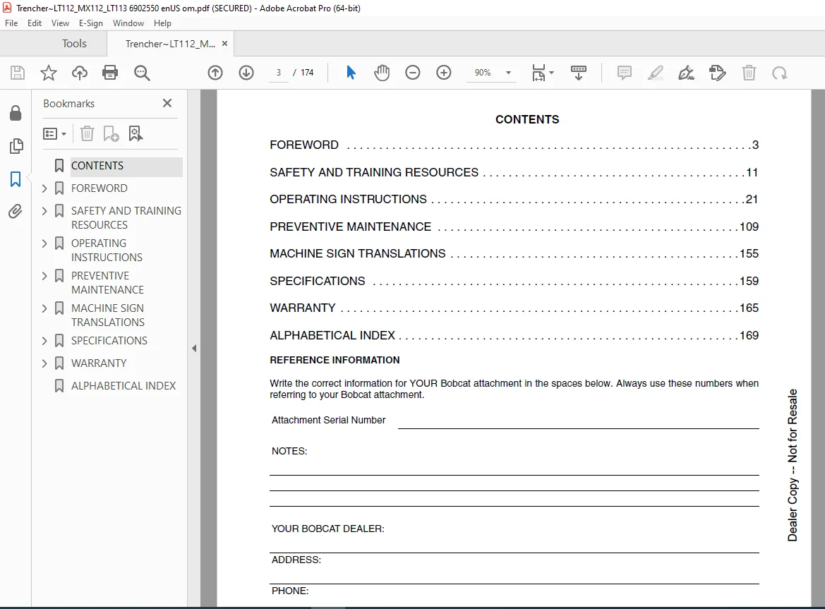
CONTENTS 3
FOREWORD 5
BOBCAT COMPANY IS IS0 9001 CERTIFIED 7
SERIAL NUMBER LOCATION 9
Attachment Serial Number 9
DELIVERY REPORT 9
ATTACHMENT IDENTIFICATION 10
LT112 And LT113 Trencher 10
MX112 Trencher 11
FEATURES AND ACCESSORIES 12
Standard Items 12
Optional Items 12
SAFETY AND TRAINING RESOURCES 13
SAFETY INSTRUCTIONS 15
Safe Operation Is The Operator’s Responsibility 15
Safe Operation Needs A Qualified Operator 15
Use Safety Rules 16
Call Before You Dig 16
Avoid Silica Dust 16
FIRE PREVENTION 17
Maintenance 17
Operation 17
Electrical 17
Hydraulic System 17
Fueling 17
Starting 17
Spark Arrester Exhaust System 17
Welding And Grinding 18
Fire Extinguishers 18
PUBLICATIONS AND TRAINING RESOURCES 19
ATTACHMENT SIGNS (DECALS) 20
LT112 And LT113 Trencher 20
MX112 Trencher 21
OPERATING INSTRUCTIONS 23
DAILY INSPECTION 25
Attachment Mounting Frame 25
Bob-Tach 26
Common Industry Interface 27
X-Change™ 28
Chain Guide 28
OPERATING PROCEDURE WITH LOADERS 29
Approved Loader Models And Requirements 29
Entering And Exiting The Loader 30
Installation 32
Hydraulic Quick Couplers 35
Control Functions 36
Operation With The Loader 37
Removal 39
OPERATING PROCEDURE WITH EXCAVATORS 40
Approved Excavator Models And Requirements 40
Entering And Exiting the Excavator 41
Installation 43
Hydraulic Quick Couplers 58
Control Functions 59
Operation With The Excavator 61
Removal 62
OPERATING PROCEDURE WITH MINI TRACK LOADERS 71
Approved Mini Track Loader Models And Requirements 71
Entering And Leaving The Operator’s Position 72
Installation 73
Installation 75
Hydraulic Quick Couplers 78
Control Functions 79
Operation With The Mini Track Loader 81
Removal 87
Removal 88
OPERATING PROCEDURE WITH SMALL ARTICULATED LOADERS 89
Approved Small Articulated Loaders Models And Requirements 89
Entering And Exiting The Small Articulated Loader 90
Installation 92
Hydraulic Quick Couplers 98
Control Functions 99
Operation With The Small Articulated Loader100
Removal102
LIFTING THE ATTACHMENT106
Procedure106
TRANSPORTING THE ATTACHMENT ON A TRAILER107
Fastening107
TRANSPORTING THE ATTACHMENT AND MACHINE ON A TRAILER109
Loading And Fastening109
PREVENTIVE MAINTENANCE111
MAINTENANCE SAFETY113
TROUBLESHOOTING115
Chart115
LUBRICATING THE ATTACHMENT116
Lubrication Locations116
REMOVAL AND INSTALLATION OF AUGER117
Procedure(s)117
Adjustment117
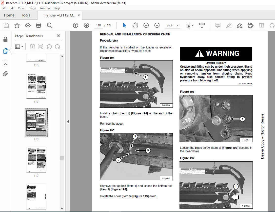
REMOVAL AND INSTALLATION OF DIGGING CHAIN118
Procedure(s)118
Adjustment119
REMOVAL AND INSTALLATION OF DIGGING CHAIN TEETH120
Procedure(s)120
LT112 AND MX112 SINGLE STANDARD PATTERNS121
Component Description121
0,61 m x 102 mm (2 ft x 4 in) Cup Tooth Pattern Installation122
0,61 m x 152 mm (2 ft x 6 in) Cup Tooth Pattern Installation123
0,61 m x 203 mm (2 ft x 8 in) Cup Tooth Pattern Installation124
LT113 SINGLE STANDARD PATTERNS125
Component Description125
0,61 m x 102 mm (2 ft x 4 in) Cup Tooth Pattern Installation126
0,61 m x 152 mm (2 ft x 6 in) Cup Tooth Pattern Installation127
0,61 m x 203 mm (2 ft x 8 in) Cup Tooth Pattern Installation128
0,91 m x 102 mm (3 ft x 4 in) Cup Tooth Pattern Installation129
0,91 m x 152 mm (3 ft x 6 in) Cup Tooth Pattern Installation130
0,91 m x 203 mm (3 ft x 8 in) Cup Tooth Pattern Installation131
LT112 AND MX112 DOUBLE STANDARD PATTERNS132
Component Description132
0,61 m x 102 mm (2 ft x 4 in) Cup Tooth Pattern Installation133
0,61 m x 102 mm (2 ft x 4 in) Carbide Tooth Pattern Installation134
0,61 m x 102 mm (2 ft x 4 in) Cup Tooth / Carbide Tooth Pattern Installation135
0,61 m x 152 mm (2 ft x 6 in) Cup Tooth Pattern Installation136
0,61 m x 203 mm (2 ft x 8 in) Cup Tooth Pattern Installation137
LT113 DOUBLE STANDARD PATTERNS138
Component Description138
0,61 m x 102 mm (2 ft x 4 in) Cup Tooth Pattern Installation139
0,61 m x 102 mm (2 ft x 4 in) Carbide Tooth Pattern Installation140
0,61 m x 102 mm (2 ft x 4 in) Cup Tooth / Carbide Tooth Pattern Installation141
0,61 m x 152 mm (2 ft x 6 in) Cup Tooth Pattern Installation142
0,61 m x 203 mm (2 ft x 8 in) Cup Tooth Pattern Installation143
0,91 m x 102 mm (3 ft x 4 in) Cup Tooth Pattern Installation144
0,91 m x 102 mm (3 ft x 4 in) Carbide Tooth Pattern Installation145
0,91 m x 102 mm (3 ft x 4 in) Cup Tooth / Carbide Tooth Pattern Installation146
0,91 m x 152 mm (3 ft x 6 in) Cup Tooth Pattern Installation147
0,91 m x 203 mm (3 ft x 8 in) Cup Tooth Pattern Installation148
LT112 SHARK PATTERNS149
Component Description149
0,61 m x 102 mm (2 ft x 4 in) Shark Tooth Pattern Installation150
0,61 m x 152 mm (2 ft x 6 in) Shark Tooth Pattern Installation151
LT113 SHARK PATTERNS152
Component Description152
0,91 m x 102 mm (3 ft x 4 in) Shark Tooth Pattern Installation153
0,91 m x 152 mm (3 ft x 6 in) Shark Tooth Pattern Installation154
ATTACHMENT STORAGE AND RETURN TO SERVICE155
Storage155
Return To Service155
MACHINE SIGN TRANSLATIONS157
MACHINE SIGN TRANSLATIONS159
Warning (6575965)159
Danger (6579914)160
SPECIFICATIONS161
(LT112 AND LT113) TRENCHER SPECIFICATIONS163
Dimensions163
Performance163
Hydraulic System164
(MX112) TRENCHER SPECIFICATIONS165
Dimensions165
Performance165
Hydraulic System166
WARRANTY167
WARRANTY169
ALPHABETICAL INDEX171
Questions? Email us: [email protected]
DESCRIPTION:
BOBCAT Trencher LT112 MX112 LT113 LT113 Operation & Maintenance Manual 6902550 PDF DOWNLOAD
FOREWORD
Maintenance
- The machine and some attachments have components that are at high temperatures under normal operating conditions. The primary source of high temperatures is the engine and exhaust system. The electrical system, if damaged or incorrectly maintained, can be a source of arcs or sparks.
- Flammable debris (leaves, straw, etc.) must be removed regularly. If flammable debris is allowed to accumulate, it can cause a fire hazard. Clean often to avoid this accumulation. Flammable debris in the engine compartment is a potential fire hazard.
- The operator’s area, engine compartment, and engine cooling system must be inspected every day and cleaned if necessary to prevent fire hazards and overheating.
- All fuels, most lubricants, and some coolant mixtures are flammable. Flammable fluids that are leaking or spilled onto hot surfaces or onto electrical components can cause a fire.
- Do not use the machine where exhaust, arcs, sparks, or hot components can contact flammable material, explosive dust, or gases.
- Check all electrical wiring and connections for damage. Keep the battery terminals clean and tight. Repair or replace any damaged part or wires that are loose or frayed.
- Battery gas can explode and cause serious injury. Use the procedure in the Operation & Maintenance Manual for connecting the battery and for jump-starting. Do not jump-start or charge a frozen or damaged battery. Keep any open flames or sparks away from batteries. Do not smoke in the battery charging area.
- Check hydraulic tubes, hoses, and fittings for damage and leakage. Never use an open flame or bare skin to check for leaks. Hydraulic tubes and hoses must be properly routed and have adequate support and secure clamps. Tighten or replace any parts that show leakage.
- Always clean fluid spills. Do not use gasoline or diesel fuel for cleaning parts. Use commercial nonflammable solvents.
- Stop the engine and let it cool before adding fuel. No smoking! Do not refuel a machine near open flames or sparks. Fill the fuel tank outdoors.
- Ultra Low Sulfur Diesel (ULSD) poses a greater static ignition hazard than earlier diesel formulations with higher Sulfur content. Avoid death or serious injury from fire or explosion. Consult with your fuel or fuel system supplier to ensure the delivery system is in compliance with fueling standards for proper grounding and bonding practices.
- Do not use ether or starting fluids on any engine that has glow plugs. These starting aids can cause an explosion and injure you or bystanders.
- Use the procedure in the Operation & Maintenance Manual for connecting the battery and for jump-starting.
- The spark arrester exhaust system is designed to control the emission of hot particles from the engine and exhaust system, but the muffler and the exhaust gases are still hot.
- Check the spark arrester exhaust system regularly to make sure it is maintained and working properly. Use the procedure in the Operation & Maintenance Manual for cleaning the spark arrester muffler (if equipped).
PLEASE NOTE:
- This is the same manual used by the dealers to diagnose and troubleshoot your vehicle
- You will be directed to the download page as soon as the purchase is completed. The whole payment and downloading process will take anywhere between 2-5 minutes
- Need any other service / repair / parts manual, please feel free to contact [email protected] . We still have 50,000 manuals unlisted
G.P