Bobcat Turbo 873 Turbo 883 Includes High Flow G Series Loader Service Manual 6900847 (10-12) – PDF DOWNLOAD
$34.95
Bobcat Turbo 873 Turbo 883 Includes High Flow G Series Loader Service Manual 6900847 (10-12) – PDF DOWNLOAD
S/N 514140001 & Above
S/N 514240001 & Above
S/N 517911001 & Above
S/N 520111001 & Above
S/N 520211001 & Above
Description
Bobcat Turbo 873 Turbo 883 Includes High Flow G Series Loader Service Manual 6900847 (10-12) – PDF DOWNLOAD
FILE DETAILS:
Bobcat Turbo 873 Turbo 883 Includes High Flow G Series Loader Service Manual 6900847 (10-12) – PDF DOWNLOAD
Language : English
Pages : 924
Downloadable : Yes
File Type : PDF
TABLE OF CONTENTS:
Bobcat Turbo 873 Turbo 883 Includes High Flow G Series Loader Service Manual 6900847 (10-12) – PDF DOWNLOAD
MAINTENANCE SAFETY 3
ALPHABETICAL INDEX 5
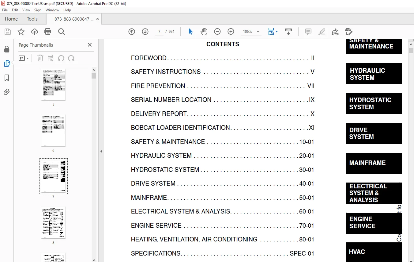
CONTENTS 7
FOREWORD 8
SAFETY INSTRUCTIONS 11
FIRE PREVENTION 13
Maintenance 13
Operation 13
Electrical 13
Hydraulic System 13
Fueling 13
Starting 13
Spark Arrestor Exhaust System 13
Welding And Grinding 14
Fire Extinguishers 14
SERIAL NUMBER LOCATION 15
Loader Serial Number 15
Engine Serial Number 15
DELIVERY REPORT 16
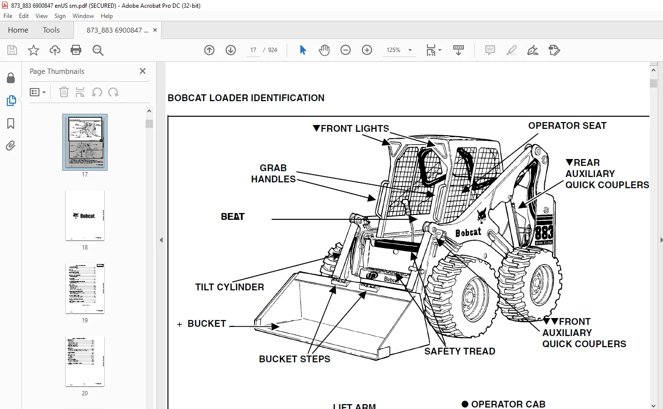
BOBCAT LOADER IDENTIFICATION 17
SAFETY & MAINTENANCE 19
LIFTING AND BLOCKING THE LOADER 21
Procedure 21
LIFT ARM SUPPORT DEVICE 23
Installing The Lift Arm Support Device 23
Removing Lift Arm Support Device 24
OPERATOR CAB 25
Description 25
Raising The Operator Cab 25
Lowering The Operator Cab 26
Emergency Exit 27
TRANSPORTING THE BOBCAT LOADER 29
Procedure 29
TOWING THE LOADER 31
Procedure For Non-Two-Speeds 31
Procedure For Two-Speeds 32
REMOTE START 33
Procedure for Loader Without Attachments Control Harness 33
Procedure for Loader With Attachments Control Harness 34
Procedure 36
SERVICE SCHEDULE 37
Chart 37
AIR CLEANER SERVICE 39
Replacing Filter Element 39
ENGINE COOLING SYSTEM 41
Cleaning The Cooling System 41
FUEL SYSTEM 43
Fuel Specifications 43
Filling The Fuel Tank 43
Fuel Filter 44
Removing Air From The Fuel System 44
Fuel Lift Pump Strainer 44
ENGINE LUBRICATION SYSTEM 45
Checking Engine Oil 45
Replacing Oil And Filter 45
HYDRAULIC / HYDROSTATIC SYSTEM 47
Checking And Adding Fluid 47
Hydraulic / Hydrostatic Filter Replacement 47
Replacing Hydraulic Fluid 48
FINAL DRIVE TRANSMISSION (CHAINCASE) 51
Checking And Adding Oil 51
Replacing The Oil 51
FAN GEARBOX 53
Checking And Adding Oil 53
BOB-TACH 55
Inspection And Maintenance 55
POWER BOB-TACH (OPTION) 57
Inspection And Maintenance 57
LUBRICATION OF THE BOBCAT LOADER 59
Procedure 59
TIRE MAINTENANCE 63
Wheel Nuts 63
Tire Rotation 63
Tire Mounting 63
HYDRAULIC SYSTEM 65
HYDRAULIC / HYDROSTATIC SCHEMATICS 71
HYDRAULIC SYSTEM INFORMATION 91
Troubleshooting 95
Tighten Procedures 96
CYLINDER (LIFT) 97
Checking 97
Removal And Installation 97
Parts Identification 99
Disassembly 100
Assembly 102
CYLINDER (TILT) 105
Checking 105
Removal And Installation 105
Parts Identification 107
Disassembly 108
CYLINDER (POWER BOB-TACH) 109
Checking 109
Removal And Installation 110
Parts Identification 111
Disassembly 112
Assembly 113
MAIN RELIEF VALVE (FOOT CONTROL) 117
Checking The Main Relief Valve At Front Auxiliary Hydraulics 117
Checking The Main Relief Valve Without Front Auxiliaries 118
Removal and Installation 120
Adjustment 121
MAIN RELIEF VALVE (AHC) 123
Checking The Main Relief Valve At Front Auxiliary Hydraulics 123
Checking The Main Relief Valve Without Front Auxiliaries 124
Removal and Installation 125
Adjustment 126
HYDRAULIC CONTROL VALVE (FOOT CONTROL) 127
Removal And Installation 127
BICS™ Valve, Removal And Installation 131
BICS™ Valve, Lift Arm Bypass Orifice Removal And Installation 132
BICS™ Valve, Check Valve Removal And Installation 133
BICS™ Valve, Lock Valve Removal And Installation 134
BICS™ Valve, Solenoid Removal And Installation 135
BICS™ Valve, Solenoid Testing 136
Identification Chart 137
Load Check Valve 137
Main Relief Valve 139
Port Relief Valve, Tilt Spool (Linkage End) 139
Port Relief Valve, Lift Spool (Bonnet End) 140
Anti-Cavitation Valve / Port Relief Valve, Tilt Spool (Bonnet End) 140
Anti-Cavitation Valve, Lift Spool (Linkage End) 141
Rubber Boot 141
Lift And Tilt Lock Block 142
Lift Spool and Detent Removal 143
Lift Spool And Detent Disassembly 145
Lift Spool and Detent Assembly 147
Lift Spool And Detent Installation 151
Tilt Spool Removal And Installation 152
Tilt Spool Disassembly And Assembly 153
Auxiliary Spool Removal And Installation (Bonnet End) 154
Auxiliary Spool Removal And Installation (Linkage End) 155
Auxiliary Plug Removal And Installation 156
Auxiliary Electric Solenoid Disassembly 157
Port-Auxiliary Section Removal And Installation 158
Cleaning And Inspection 158
HYDRAULIC CONTROL VALVE (ADVANCED CONTROL SYSTEM) (ACS) (AHC) 159
Description 159
Actuator Removal And Installation (In Loader) 159
Removal And Installation 161
BICS™ Valve Removal And Installation 165
BICS™ Valve, Lift Arm Bypass Orifice Removal And Installation 167
BICS™ Valve Check Valve Removal And Installation 168
BICS™ Valve Lock Valve Removal And Installation 169
BICS™ Valve Solenoid Removal And Installation 170
BICS™ Valve Solenoid Testing 171
Actuator Removal And Installation 172
Identification Chart 173
Lift Base End Restrictor 173
Load Check Valve 174
Main Relief Valve 175
Port Relief Valve 176
Anti-Cavitation Valve / Port Relief Valve 177
Anti-Cavitation Valve 178
Lift Spool Removal 179
Tilt Spool Removal And Installation 180
Lift and Tilt Spool Disassembly And Assembly 181
Auxiliary Spool Removal And Installation 182
Auxiliary Electric Solenoid Disassembly 183
Port-Auxiliary Section Disassembly 184
Cleaning And Inspection 184
LIFT ARM BYPASS CONTROL VALVE 185
Inspecting 185
Additional Inspection For Loaders With Advanced Hand Controls 185
Removal And Installation 185
Disassembly And Assembly 186
HYDRAULIC PUMP (ALUMINUM) 187
Check The Output Of The Pump 187
Removal And Installation 188
Identification 189
Disassembly 190
Inspection 192
Assembly 193
HYDRAULIC PUMP (ALUMINUM HIGH FLOW) 195
Check The Output Of The Pump 195
Removal And Installation 196
Identification 198
Disassembly 199
Inspection 203
Assembly 204
HYDRAULIC PUMP (CAST IRON) 209
Check The Output Of The Hydraulic Pump Without Power Bob-Tach 209
Check The Output Of The Hydraulic Pump With Power Bob-Tach 211
Removal And Installation 212
Identification 214
Disassembly And Assembly 215
HYDRAULIC PUMP (CAST IRON HIGH FLOW) 219
Check The Output Of The Hydraulic Pump Without Power Bob-Tach 219
Check The Output Of The Hydraulic Pump With Power Bob-Tach 220
Removal And Installation 222
Identification 224
Disassembly And Assembly 225
HYDRAULIC / HYDROSTATIC FILTER 233
Housing Removal And Installation 233
Mount Removal And Installation 234
HYDRAULIC FLUID RESERVOIR 235
Draining The Fluid Reservoir 235
Removal And Installation 236
Hydraulic Fluid Screen 239
BUCKET POSITION VALVE (873 – S/N 514147758 & BELOW) 241
Solenoid Removal And Installation 241
Solenoid Testing 241
Removal And Installation 242
BUCKET POSITION VALVE (873 – S/N 514147759 & Above & 883) 245
Solenoid Removal And Installation 245
Solenoid Testing 245
Removal And Installation 246
Disassembly And Assembly 247
SELECT VALVE 249
Checking The High Flow Pump Relief Valve 249
Removal And Installation 251
Disassembly And Assembly 253
Solenoid Testing 258
REAR AUXILIARY DIVERTER VALVE (SINGLE SHUTTLE) 259
Removal And Installation 259
Disassembly 260
Inspection 261
Solenoid Testing 261
Assembly 261
POWER BOB-TACH BLOCK (6674305 ALUMINUM) 263
Removal And Installation 263
Disassembly And Assembly 265
POWER BOB-TACH BLOCK (6676547 ALUMINUM) 271
Removal And Installation 271
Disassembly And Assembly 273
POWER BOB-TACH BLOCK (6677646-CAST IRON) 279
Removal And Installation 279
Disassembly And Assembly 280
POWER BOB-TACH BLOCK (6678206-CAST IRON) 287
Removal And Installation 287
Disassembly And Assembly 288
POWER BOB-TACH BLOCK (6678554-CAST IRON) 297
Removal And Installation 297
Disassembly And Assembly 298
AUXILIARY PRESSURE RELEASE (ACCUMULATOR) 307
Removal and Installation 307
Disassembly And Assembly 309
HYDROSTATIC SYSTEM 311
HYDROSTATIC SYSTEM INFORMATION 313
Troubleshooting Chart 313
Replenishing Valve Function 314
HYDROSTATIC MOTOR 315
Removal And Installation 315
Parts Identification 317
Disassembly 318
Inspection 321
Assembly 322
HYDROSTATIC MOTOR (TWO-SPEED) 325
Removal And Installation 325
Parts Identification 328
Disassembly 330
Inspection 337
Assembly 339
HYDROSTATIC MOTOR CARRIER 345
Removal and Installation 345
Parts Identification 347
Disassembly 348
Assembly 350
CHARGE PRESSURE 353
Sender Removal And Installation 353
HYDROSTATIC PUMP 355
Replenishing / High Pressure Relief Valve 355
Charge Pressure Relief Valve 356
Removal And Installation 357
Parts Identification (Right Half) 360
Parts Identification (Left Half) 362
Hydraulic Pump Removal 364
Disassembly 365
Assembly 373
DRIVE BELT 381
Shield Removal And Installation 381
Adjustment 382
Replacement 382
Tensioner Pulley Removal And Installation 383
Tensioner Pulley Tension Spring 385
OIL COOLER 387
Hydraulic Oil Cooler Removal and Installation 387
OIL COOLER (SEAL TO CONNECT) (STC) 391
Hydraulic Oil Cooler Removal and Installation 391
DRIVE SYSTEM 393
BRAKE 395
Pedal Removal And Installation 395
Pedal Disassembly And Assembly 396
Switch Operated Parking Brake 396
Disc Removal And Installation 397
BRAKE (TWO-SPEED) 401
Block Removal And Installation 401
Block Disassembly And Assembly 403
DRIVE COMPONENTS 409
Axle Seal Removal And Installation 409
Axle, Sprocket And Bearings Removal And Installation 411
Drive Chain Removal And Installation 416
CHAINCASE 417
Front Chaincase Cover Removal And Installation 417
Rear Chaincase Cover Removal And Installation 417
MAINFRAME 419
SEAT BAR 423
Removal And Installation 423
Assembling Components 425
Compression Spring Disassembly And Assembly 427
OPERATOR CAB 429
Gas Cylinder Removal And Installation 429
Gas Cylinder Bracket Disassembly And Assembly 431
Removal And Installation 432
OPERATOR SEAT 435
Removal And Installation 435
Seat Belt Removal And Installation 435
OPERATOR SEAT (SUSPENSION) 437
Removal And Installation 437
Slide Rail Removal And Installation 438
Cushion Removal And Installation 438
Back Removal And Installation 439
Shock Removal And Installation 440
BOB-TACH 441
Removal And Installation 441
Bob-Tach Lever And Wedge 442
Pivot Pin Bushing And Seal Replacement 443
POWER BOB-TACH (883) 445
Removal And Installation 445
Power Bob-Tach Lever And Wedge 446
Pivot Pin Bushing And Seal Replacement 447
LIFT ARMS 449
Stabilizer Bar Removal And Installation 449
Link Removal And Installation 450
Removal And Installation 452
REAR GRILL 455
Removal And Installation 455
REAR DOOR 457
Removal And Installation 457
Adjusting The Rear Door Latch 458
FUEL TANK 459
Removal And Installation 459
Fuel Level Sender 460
CONTROL PEDALS 461
Removal And Installation 461
Pedal Adjustment 461
CONTROL PEDALS (ACS) 463
Foot Sensor Removal And Installation 463
Foot Pedal Removal And Installation 464
Foot Pedal Linkage Disassembly And Assembly 465
CONTROL PANEL 467
Removal and Installation 467
Steering Lever Boot 469
CONTROL HANDLE 471
Shock Removal And Installation 471
Shaft Removal And Installation 471
Shaft Disassembly And Assembly 471
Lever Removal And Installation 473
Steering Lever Boot 473
Linkage Removal And Installation 474
Linkage Neutral Adjustment 478
CONTROL HANDLE (ADVANCED HAND CONTROL) (AHC) 485
Components Identification 485
Handle Control Unit Removal And Installation 486
Control Handle Removal and Installation 489
Control Handle Disassembly and Assembly 489
Control Lever Removal and Installation 490
Control Lever Boot 490
CONTROL HANDLE (ADVANCED HAND CONTROL) (AHC) (W/ PUSH BUTTON FLOAT) 491
Components Identification 491
Handle Sensor Removal And Installation 492
Control Handle Removal and Installation 494
Control Handle Disassembly and Assembly 495
Control Lever Removal and Installation 495
Control Lever Boot 496
CONTROL HANDLE (ADVANCED CONTROL SYSTEM) (ACS) ADVANCED HAND CONTROL 497
Components Identification 497
Handle Sensor Removal And Installation 498
Control Handle Removal and Installation 501
Control Handle Disassembly and Assembly 502
Control Lever Removal and Installation 502
Control Lever Boot 503
CONTROL HANDLE (ADVANCED CONTROL SYSTEM) (ACS) SELECTABLE HAND / FOOT CONTROL 505
Components Identification 505
Handle Sensor Removal And Installation 506
Control Handle Removal and Installation 509
Control Handle Disassembly and Assembly 510
Control Lever Removal and Installation 510
Control Lever Boot 511
ELECTRICAL SYSTEM & ANALYSIS 513
ELECTRICAL SCHEMATICS 517
ELECTRICAL SYSTEM INFORMATION 527
Troubleshooting Chart 529
Description 530
Fuse Location 532
Relay Switch Location 532
Solenoid Test 533
BATTERY 535
Removal And Installation 535
Servicing The Electrical System 537
Using A Booster Battery (Jump Starting) 538
ALTERNATOR (55 AMP) 539
Adjusting The Alternator Belt 539
Alternator Output Test 539
Rectifier (Diode) Test 540
Alternator Regulator Test 541
Removal And Installation 542
Disassembly 543
Stator Continuity Test 543
Stator Ground Test 543
Rotor Continuity Test 544
Rotor Ground Test 544
Rectifier Continuity (Diode) Test 544
Assembly 545
ALTERNATOR (90 AMP) 547
Adjusting The Alternator Belt 547
Alternator Identification 547
Charging System Check 548
Alternator Voltage Test 549
Low Voltage Test 549
High Voltage Test 550
Removal And Installation 551
Rectifier Continuity (Diode) Test 552
Alternator Regulator Test 553
Disassembly 553
Stator Continuity Test 554
Stator Ground Test 554
Rotor Continuity Test 554
Rotor Ground Test 554
Assembly 555
STARTER 557
Removal And Installation 557
Parts Identification 558
Disassembly And Assembly 559
External Pinion 563
Inspection And Repair 564
Magnetic Switch Test 567
No Load Test 568
INSTRUMENT PANEL 569
Left Panel 569
Right Panel – Standard Instrument Panel (With Key Switch) [Figure 60-50-2] 570
Right Panel – (Deluxe) (With Keyless Start) [Figure 60- 50-3] 571
Right Panel Setup Display Options (Deluxe) 573
Passwords 574
Option and Field Accessory Panels 575
Standard Panel Removal And Installation (Right Side) 576
Deluxe Panel Removal And Installation (Right Side) 577
Standard & Deluxe Panel Removal And Installation (Left Side) 578
Front Accessory Panel Removal And Installation 579
LIGHTS 581
Front Removal And Installation 581
Rear Removal And Installation 582
BOBCAT CONTROLLER 583
Identification Chart 583
Removal And Installation 584
DIAGNOSTICS 585
Service Codes 585
BICS™ SYSTEM 587
Inspecting The BICS™ Controller (Engine STOPPED – Key ON) 587
Inspecting Deactivation Of The Auxiliary Hydraulics System (Engine STOPPED – Key ON) 587
Inspecting The Seat Bar Sensor (Engine RUNNING) 587
Inspecting The Traction Lock (Engine RUNNING) 587
Inspecting The Lift Arm Bypass Control 588
Additional Inspection For Loaders With Advanced Hand Controls (AHC) 588
Troubleshooting Chart 589
Troubleshooting Guide 590
SEAT BAR SENSOR 591
Troubleshooting Chart 591
Test 592
Removal And Installation 593
BICS™ Circuit Test 594
TRACTION LOCK 597
Troubleshooting Chart 597
Removal And Installation (Single Speed) 598
Description Of The Control System (Single Speed) 600
Inspecting The Control System (Single Speed) 600
ADVANCED HAND CONTROL (AHC) SYSTEM 601
Components Identification 601
Troubleshooting Guide 602
Parts Identification 603
AHC Controller Removal And Installation 604
Handle Control Unit Connector 605
Switch Handle Removal And Installation 606
Actuators Disassembly and Assembly 609
ADVANCED HAND CONTROL (AHC) SYSTEM (W/ PUSH BUTTON FLOAT) 611
Components Identification 611
Troubleshooting Guide 612
Controller, Connector And Wire Identification 613
AHC Controller Removal And Installation 614
Handle Control Unit Removal And Installation 616
Handle Control Unit Connector 618
Switch Handle Removal And Installation 619
Actuators Disassembly and Assembly 622
ADVANCED CONTROL SYSTEM (ACS) 625
Components Identification 625
Troubleshooting Guide 627
Controller, Connector And Wire Identification 628
ACS Controller Removal And Installation 629
Handle Sensor Connector 630
Switch Handle Removal 631
Switch Handle Installation 633
Actuators Disassembly and Assembly 636
Handle Lock Solenoid Removal And Installation 638
Handle Lock Solenoid Disassembly And Assembly 638
Handle Lock Solenoid Connector 639
Calibration Of The ACS System 640
Switchable Hand / Foot Controls Calibration Procedure 640
Hand Controls Only Calibration Procedure 641
Foot Sensor Disassembly And Assembly 643
Foot Sensor Connector 643
Foot Lock Solenoid Removal And Installation 644
Foot Lock Solenoid Connector 645
ELECTRICAL / HYDRAULIC CONTROLS REFERENCE 647
Controls Identification Chart 647
ENGINE SERVICE 649
TROUBLESHOOTING 651
Chart 651
ENGINE SPEED CONTROL 653
Removal And Installation 653
Speed Control Cable 655
Speed Control Linkage 655
MUFFLER 657
Removal And Installation 657
AIR CLEANER 659
Housing Removal And Installation 659
RADIATOR 661
Removal And Installation 661
COOLING FAN 663
Drive Tension Pulley Removal And Installation 663
Gearbox/Blower Housing Removal And Installation 664
Blower Removal And Installation 667
Gearbox Parts Identification 668
Gearbox Disassembly 669
Gearbox Assembly 674
Gearbox, Checking Backlash 679
ENGINE COMPONENTS AND TESTS 683
Engine Compression, Checking 683
Glow Plug, Checking 684
Fuel Shut-Off Solenoid, Checking 685
Fuel Shut-Off Solenoid Removal And Installation 686
Fuel Injection Pump Removal 687
Fuel Injection Pump Timing 689
Fuel Injection Pump Installation 690
Fuel Injector Removal And Installation 692
Fuel Injector, Checking 693
Fuel Injector Disassembly 694
Fuel Injector Assembly 695
Timing Belt Inspection 697
Timing Belt Removal 698
Timing Belt Installation 699
Timing Belt, Replacement In the Loader 703
Valve Clearance Adjustment 708
Valve Timing, Checking 709
Valve Timing, Checking (Cont’d) 710
Thermostat, Oil Pressure Control Valves & Heater Connections 711
ENGINE 715
Removal And Installation 715
Mount Replacement 721
FLYWHEEL AND HOUSING 723
Flywheel Removal And Installation 723
Ring Gear Removal And Installation 723
Flywheel Housing Removal And Installation 723
RPM SENSOR 725
Adjustment 725
RECONDITIONING THE ENGINE 727
Deutz Engine Tools Identification Chart 727
Disassembly 728
Assembly 733
Cylinder, Checking 748
Camshaft Bearing, Checking 749
Camshaft Bearing, Removal And Installation 750
Control Rod Guide Bushing Removal 751
Control Rod Guide Bushing Installation 753
Rear Cover Seal Removal And Installation 757
Crankshaft, Checking 758
Connecting Rod, Checking 759
Piston, Checking 762
Piston Pin, Checking 763
Piston Rings Installation 763
Piston Installation On The Connecting Rod 764
Cylinder Head Disassembly 765
Valves, Checking 766
Valve Seats, Checking 767
Valve Spring, Checking 767
Cylinder Head Assembly 767
Rocker Arm And Bracket, Checking 769
Front Cover Disassembly 770
Front Cover Assembly 775
Turbo Charger Removal And Installation 785
Crankshaft Gear Mounting Bolt Torque Procedure 787
HEATING, VENTILATION, AIR CONDITIONING 789
AIR CONDITIONING SYSTEM FLOW 792
Principals 792
Chart 793
COMPONENTS 795
Identification 795
SAFETY 799
Safety Equipment 799
REGULAR MAINTENANCE 801
Filter Elements Removal And Installation 801
Compressor Drive Belt Inspection 802
Cleaning The Condenser 803
BASIC TROUBLESHOOTING 805
Poor A/C Performance 805
Cleaning The A/C Evaporator Coil & Heater Coil 806
Receiver/Drier Sight Glass Inspection 808
Compressor Drive Belt Inspection 809
Checking The Electrical System 810
Engine Coolant Bypassing The Heater Valve 818
Heater Valve Not Opening Or Closing 819
GENERAL AIR CONDITIONING SERVICE GUIDELINES 821
Compressor Oil 821
Compressor Oil Check 822
Component Replacement And Refrigeration Leaks 823
SYSTEM TROUBLESHOOTING CHART 825
TEMPERATURE/PRESSURE 829
Chart 829
AIR CONDITIONING SERVICE 831
Chart 831
SYSTEM CHARGING AND RECLAMATION 833
Reclamation Procedure 833
Charging Procedure With A Manifold Gauge Set 835
Charging Procedure 836
COMPRESSOR 839
Removal And Installation 839
Compressor Clutch Disassembly 840
CONDENSER 845
Removal And Installation 845
RECEIVER/DRIER 847
Removal And Installation 847
PRESSURE RELIEF VALVE 849
Removal And Installation 849
PRESSURE SWITCH 851
Removal And Installation 851
EVAPORATOR/HEATER UNIT 853
Removal And Installation 853
Disassembly And Assembly 854
THERMOSTAT 855
Removal And Installation 855
EXPANSION VALVE 857
Removal And Installation 857
EVAPORATOR 859
Removal And Installation 859
HEATER COIL 861
Removal And Installation With A/C 861
Removal And Installation Without A/C 862
BLOWER FAN 865
Removal And Installation 865
Disassembly And Assembly 866
Wire Connector Removal and Installation 868
HEATER VALVE 871
Removal and Installation 871
Disassembly And Assembly 872
SPECIFICATIONS 875
LOADER SPECIFICATIONS (873) 877
Machine Dimensions 877
Performance 878
Controls 878
Engine 878
Hydraulic System 879
Electrical 879
Drive System 880
Capacities 880
Tires 880
LOADER SPECIFICATIONS (883) 881
Machine Dimensions 881
Performance 882
Controls 882
Engine 882
Hydraulic System 883
Electrical 883
Drive System 884
Capacities 884
Tires 884
ENGINE SPECIFICATIONS 885
General 885
Fuel System 885
Valve and Valve Guide and Seat Insert 886
Pistons and Rings 887
Connecting Rod 887
Cylinder Head and Block 888
Crankshaft and Main Bearings 888
Camshaft and Bearings 888
Oil Pump 888
LOADER TORQUE 889
Specifications 889
TORQUE SPECIFICATIONS FOR BOLTS 893
Torque For General SAE Bolts 893
Torque For General Metric Bolts 894
HYDRAULIC CONNECTION SPECIFICATIONS 895
O-ring Face Seal Connection 895
Straight Thread O-ring Fitting 895
Tubelines And Hoses 895
Flare Fitting 896
O-ring Flare Fitting 897
Port Seal Fitting 899
HYDRAULIC / HYDROSTATIC FLUID SPECIFICATIONS 901
Specifications 901
CONVERSIONS 903
Decimal And Millimeter Equivalents 903
U S To Metric Conversion Chart 903
SERVICE MANUAL REVISION 905
873/873H-1 905
873/873H-2 907
873/873H-3 909
873/883-4 913
873/883-5 915
873/883-6 917
873/883-7 919
873/883-8 921
873/883-9 923
DESCRIPTION:
Bobcat Turbo 873 Turbo 883 Includes High Flow G Series Loader Service Manual 6900847 (10-12) – PDF DOWNLOAD
S/N 514140001 & Above
S/N 514240001 & Above
S/N 517911001 & Above
S/N 520111001 & Above
S/N 520211001 & Above
FOREWORD:
This manual is for the Bobcat loader mechanic. It provides necessary servicing and adjustment procedures for the Bobcat loader and its component parts and systems. Refer to the Operation & Maintenance Manual for operating instructions, starting procedure, daily checks, etc.
The following publications provide information on the safe use and maintenance of the Bobcat machine and attachments:
Contact us: [email protected]
IMAGES PREVIEW OF THE MANUAL:
PLEASE NOTE:
- This is not a physical manual but a digital manual – meaning no physical copy will be couriered to you. The manual can be yours in the next 2 mins as once you make the payment, you will be directed to the download page IMMEDIATELY.
- This is the same manual used by the dealers inorder to diagnose your vehicle of its faults.
- Require some other service manual or have any queries: please WRITE to us at [email protected]
S.V