Boeing 757-200 Flight Crew Operations Manual – PDF
$49.95
Boeing 757-200 Flight Crew Operations Manual – PDF DOWNLOAD
Description
Boeing 757-200 Flight Crew Operations Manual – PDF DOWNLOAD
FILE DETAILS:
Boeing 757-200 Flight Crew Operations Manual – PDF DOWNLOAD
Language : English
Pages : 1266
Downloadable : Yes
File Type : PDF
IMAGES PREVIEW OF THE MANUAL:
TABLE OF CONTENTS:
Boeing 757-200 Flight Crew Operations Manual – PDF DOWNLOAD
Title Page 1
Preface 3
Chapter Table of Contents 3
V1V2 Model Identification 5
Introduction 7
General 7
Organization 9
Page Numbering 9
Example Page Number 9
Page Identification 9
Example Page Identification 10
Warnings, Cautions, and Notes 10
Flight Crew Operations Manual Configuration 10
Airplane Effectivities 11
Abbreviations 13
V1V2 Revision Record 21
V1V2 List of Effective Pages 31
Bulletin Record 41
Limitations 213
Table of Contents 213
Operating Limitations 215
General 215
Airplane General 215
Operational Limitations 215
Non-AFM Operational Information 215
Airplane Weight Restrictions 216
Flight Deck Security Door 216
Door Mounted Escape Slides 217
Air Conditioning 217
Auto Flight 217
Aircraft Communications Addressing and Reporting System (ACARS) 217
Engine 218
Engine Fuel System 218
Reverse Thrust 218
Flight Controls 218
Navigation 218
Warning systems 219
Ground Proximity Warning System (GPWS) Look-Ahead Alerting 219
Normal Procedures 221
Table of Contents 221
11 Introduction 223
General 223
Scan Flow and Areas of Responsibility 223
Normal Procedures Philosophy and Assumptions 224
Configuration Check 225
Crew Duties 226
Control Display Unit (CDU) Procedures 227
Autopilot Flight Director System (AFDS) Procedures 227
Preflight and Postflight Scan Flow 228
Areas of Responsibility – Captain as Pilot Flying or Taxiing 229
Areas of Responsibility – First Officer as Pilot Flying or Taxiing 230
21 Amplified Procedures 231
Preliminary Preflight Procedure – Captain or First Officer 231
CDU Preflight Procedure – Captain and First Officer 233
Exterior Inspection 235
Preflight Procedure – First Officer 241
Preflight Procedure – Captain 250
Before Start Procedure 255
Pushback or Towing Procedure 258
Engine Start Procedure 259
Engine Start Procedure 261
Before Taxi Procedure 262
Before Takeoff Procedure 264
Takeoff Procedure 265
Takeoff Flap Retraction Speed Schedule 267
Climb and Cruise Procedure 268
Descent Procedure 269
Approach Procedure 270
Flap Extension Schedule 270
Landing Procedure – ILS 271
Landing Procedure – Instrument Approach Using VNAV 272
Go-Around and Missed Approach Procedure 274
Landing Roll Procedure 275
After Landing Procedure 276
Shutdown Procedure 277
Secure Procedure 279
Supplementary Procedures 281
Table of Contents 281
05 Introduction 287
General 287
1 Airplane General, Emer Equip, Doors, Windows 289
Doors 289
Entry Door Closing 289
Entry Door Opening 289
Flight Deck Door Access System Test 290
Windows 290
Flight Deck Window Closing 290
Flight Deck Window Opening 290
Lights 291
Indicator lights test 291
Emergency Equipment 291
Oxygen Mask Microphone Test 291
2 Air Systems 293
Air Conditioning Packs 293
Ground Conditioned Air Use 293
Packs Off Takeoff 293
APU To Pack Takeoff 294
3 Anti-Ice, Rain 295
Ice Protection 295
Anti-Ice Use 295
Windshield Wiper Use 295
4 Automatic Flight 297
AFDS 297
AFDS Operation 297
Heading Hold 297
Heading Select 298
Altitude Hold 298
Flight Level Change, Climb or Descent 298
Vertical Speed, Climb or Descent 299
Intermediate Level Off 300
Speed Intervention 300
Autothrottle Operation 301
Instrument Approach Using (V/S) 302
Circling Approach 303
Autoland Status Annunciator Test 304
Autoland Status Annunciator Reset 304
5 Communications 305
Cockpit Voice Recorder Test 305
Aircraft Communications Addressing and Reporting System (ACARS) 306
6 Electrical 307
Electrical Power Up 307
Electrical Power Down 308
Operation With Less Than 90 KVA External Power Source 308
Before Start Procedure 308
Before Taxi Procedure 309
Shutdown Procedure 309
Standby Power Test 310
Transfer From External Power To APU Power 310
Hydraulic Generator Test 311
7 Engines, APU 313
Engines 313
Engine Crossbleed Start 313
Engine Ground Pneumatic Start 313
Reduced Thrust Selection Prior To Takeoff 313
Reduced Thrust Selection Prior To Takeoff 314
Reduced Takeoff Thrust Change or Cancellation 314
Reduced Takeoff Thrust Change or Cancellation 315
Reduced Climb Thrust Change or Cancellation 315
Reduced Climb Thrust Change or Cancellation 316
Reduced Climb Thrust Selection In-flight 316
8 Fire Protection 317
Engine, APU and Cargo Fire/Overheat Test 317
Wheel Well Fire Detection Test 317
10 Flight Instruments, Displays 319
Flight Recorder Test 319
Heading Reference Switch Operation 319
QFE Operation 320
11 Flight Management, Navigation 321
Transponder Test (TCAS equipped airplanes) 321
Weather Radar Test 321
IRS 322
Align Lights Flashing 322
Fast Realignment 323
High Latitude Alignment 323
Position Entry Using IRS Mode Selector Panel 323
Lateral Navigation 324
Alternate Route Entry/Activation 324
Direct To A Waypoint Using Overwrite 324
Estimate For Alternate 324
Holding Pattern Entry 325
Holding Pattern Exit 325
Intercept A Leg Or Course To A Waypoint Using Overwrite 326
Lateral Offset 326
Leg Modification 327
Route Removal 327
SID Change Or Runway Change 328
STAR, Profile Descent Or Approach Change 328
Vertical Navigation 329
Climb, Cruise Or Descent Speed Schedule Change 329
Climb Or Descent Direct To MCP Altitude 329
Cruise Altitude Change 329
Speed/Altitude Constraint At Waypoint 330
Speed/Altitude Transition And Restriction 330
Temporary Altitude Restriction 330
Temporary Speed Restriction 331
Performance Data Entries 331
Descent Forecast 331
Step Climb Evaluation 331
Waypoint Winds 331
Additional CDU Functions 332
Fix Page Entries 332
HSI Plan Mode Control 332
Navaid Inhibit 332
Update Active Navigation Database 333
12 Fuel 335
Fuel Balancing 335
Fuel Quantity Test 335
15 Warning Systems 337
EICAS Test 337
Takeoff Configuration Warning Test 337
Landing Configuration Warning Test 337
Stall Warning Test 338
Event Record 338
16 Adverse Weather 339
Introduction 339
Takeoff – Wet or Contaminated Runway Conditions 339
Cold Weather Operations 340
Exterior Inspection 340
Engine Start Procedure 341
Engine Anti-ice Operation – On the Ground 341
Before Taxi Procedure 342
Taxi-Out 342
De-icing / Anti-icing 343
Before Takeoff Procedure 343
Takeoff Procedure 344
Engine Anti-ice Operation – In-flight 344
Wing Anti-ice Operation – In-flight 345
Cold Temperature Altitude Corrections 346
After Landing Procedure 348
Secure Procedure 349
Hot Weather Operation 350
Moderate to Heavy Rain, Hail or Sleet 350
Turbulence 351
Severe Turbulence 351
Windshear 352
Avoidance 352
Precautions 353
Performance Inflight 355
Section 757-200 535E4 LB FAA T 357
General 361
Takeoff Speeds 361
V1(MCG) 362
Maximum Allowable Clearway 362
Clearway and Stopway V1 Adjustments 362
Stab Trim Setting 362
VREF (KIAS) 363
Flap Maneuver Speeds 364
Slush/Standing Water Takeoff 365
Slippery Runway Takeoff 367
Takeoff EPR 371
Assumed Temperature Reduced Thrust 371
Max Climb EPR 372
Go-around EPR 373
Flight With Unreliable Airspeed / Turbulent Air Penetration 374
All Engine – 535E4 377
Long Range Cruise Maximum Operating Altitude 377
Long Range Cruise Control 378
Long Range Cruise Enroute Fuel and Time – Low Altitudes 379
Long Range Cruise Enroute Fuel and Time – High Altitudes 380
Long Range Cruise Wind-Altitude Trade 381
Descent at 78/290/250 381
Holding 381
Advisory Information 383
Normal Configuration Landing Distance 383
Non-Normal Configuration Landing Distance 385
Recommended Brake Cooling Schedule 393
Engine Inoperative – 535E4 395
Initial Max Continuous EPR 395
Max Continuous EPR 396
Driftdown Speed/Level Off Altitude 398
Driftdown/LRC Cruise Range Capability 398
Long Range Cruise Altitude Capability 399
Long Range Cruise Control 400
Long Range Cruise Diversion Fuel and Time 401
Holding 402
Alternate Thrust Setting 403
Takeoff Performance 403
Takeoff Speeds 403
Enroute Performance 403
Landing Performance 403
Takeoff %N1 404
Go-around %N1 405
Max Climb %N1 406
Max Cruise %N1 406
Alternate Thrust Setting – Engine Inoperative 407
Initial Max Continuous %N1 407
Max Continuous %N1 408
Gear Down – 535E4 411
210 KIAS Max Climb EPR 411
Long Range Cruise Altitude Capability 411
Long Range Cruise Control 412
Long Range Cruise Enroute Fuel and Time 413
Descent at VREF30 + 80 413
Holding 414
Gear Down, Engine Inop – 535E4 415
Driftdown Speed/Level Off Altitude 415
Long Range Cruise Altitude Capability 415
Long Range Cruise Control 416
Long Range Cruise Diversion Fuel and Time 417
Holding 418
Text 419
Introduction 419
General 419
Takeoff Speeds 419
V1(MCG) 419
Clearway and Stopway V1 Adjustments 420
Stab Trim 420
VREF 420
Flap Maneuver Speeds 420
Slush/Standing Water Takeoff 420
Slippery Runway Takeoff 421
Anti-Skid Inoperative 421
Brakes Deactivated 422
Takeoff EPR 422
Max Climb EPR 423
Go-around EPR 423
Flight with Unreliable Airspeed / Turbulent Air Penetration 423
All Engines 423
Long Range Cruise Maximum Operating Altitude 423
Long Range Cruise Control 423
APU Operation During Flight 424
Long Range Cruise Enroute Fuel and Time 424
Long Range Cruise Wind-Altitude Trade 424
Descent 424
Holding 424
Advisory Information 425
Normal Configuration Landing Distance 425
Non-normal Configuration Landing Distance 425
Recommeded Brake Cooling Schedule 426
Engine Inoperative 427
Initial Max Continuous EPR 427
Max Continuous EPR 427
Driftdown Speed/Level Off Altitude 427
Driftdown/LRC Range Capability 427
Long Range Cruise Altitude Capability 428
Long Range Cruise Control 428
APU Operation During Flight 428
Long Range Cruise Diversion Fuel and Time 428
Holding 428
Alternate Thrust Setting 429
Introduction 429
Takeoff Performance 429
Takeoff Speeds 429
Enroute Performance 429
Landing Performance 429
Takeoff %N1/Go-around %N1 430
Max Climb %N1 430
Max Cruise %N1 430
Alternate Thrust Setting, Engine Inoperative 430
Initial Max Continuous %N1 430
Max Continuous %N1 430
Gear Down 430
Section 757-200 PW2037 LB FAA T 433
General 437
Takeoff Speeds 437
V1(MCG) 438
Maximum Allowable Clearway 438
Clearway and Stopway V1 Adjustments 438
Stab Trim Setting 438
VREF (KIAS) 439
Flap Maneuver Speeds 440
Slush/Standing Water Takeoff 441
Slippery Runway Takeoff 443
Takeoff EPR 447
Assumed Temperature Reduced Thrust 447
TO1 Takeoff Speeds 448
TO1 V1(MCG) 448
TO1 Slush/Standing Water Takeoff 449
TO1 Slippery Runway Takeoff 451
TO1 Takeoff EPR 453
TO2 Takeoff Speeds 454
TO2 V1(MCG) 454
TO2 Slush/Standing Water Takeoff 455
TO2 Slippery Runway Takeoff 457
TO2 Takeoff EPR 459
Max Climb EPR 460
Go-around EPR 461
Flight With Unreliable Airspeed / Turbulent Air Penetration 462
All Engine – PW2037 465
Long Range Cruise Maximum Operating Altitude 465
Long Range Cruise Control 466
Long Range Cruise Enroute Fuel and Time – Low Altitudes 467
Long Range Cruise Enroute Fuel and Time – High Altitudes 468
Long Range Cruise Wind-Altitude Trade 468
Descent at 78/290/250 469
Holding 469
Advisory Information 471
Normal Configuration Landing Distance 471
Non-Normal Configuration Landing Distance 473
Recommended Brake Cooling Schedule 481
Engine Inoperative – PW2037 483
Initial Max Continuous EPR 483
Max Continuous EPR 484
Driftdown Speed/Level Off Altitude 486
Driftdown/LRC Cruise Range Capability 486
Long Range Cruise Altitude Capability 487
Long Range Cruise Control 488
Long Range Cruise Diversion Fuel and Time 489
Holding 490
Alternate Thrust Setting 491
Takeoff Performance 491
Takeoff Speeds 491
Enroute Performance 491
Landing Performance 491
Takeoff %N1 492
Go-around %N1 493
Max Climb %N1 494
Max Cruise %N1 495
Initial Max Continuous %N1 496
Max Continuous %N1 497
Gear Down – PW2037 501
210 KIAS Max Climb EPR 501
Long Range Cruise Altitude Capability 501
Long Range Cruise Control 502
Long Range Cruise Enroute Fuel and Time 503
Descent at VREF30+80 503
Holding 504
Gear Down, Engine Inop – PW2037 505
Driftdown Speed/Level Off Altitude 505
Long Range Cruise Altitude Capability 505
Long Range Cruise Control 506
Long Range Cruise Diversion Fuel and Time 507
Holding 508
Text 509
Introduction 509
General 509
Takeoff Speeds 509
V1(MCG) 509
Clearway and Stopway V1 Adjustments 510
Stab Trim 510
VREF 510
Flap Maneuver Speeds 510
Slush/Standing Water Takeoff 510
Slippery Runway Takeoff 511
Anti-Skid Inoperative 511
Brakes Deactivated 512
Takeoff EPR 512
Max Climb EPR 513
Go-around EPR 513
Flight with Unreliable Airspeed / Turbulent Air Penetration 513
All Engines 513
Long Range Cruise Maximum Operating Altitude 513
Long Range Cruise Control 513
APU Operation During Flight 514
Long Range Cruise Enroute Fuel and Time 514
Long Range Cruise Wind-Altitude Trade 514
Descent 514
Holding 514
Advisory Information 515
Normal Configuration Landing Distance 515
Non-normal Configuration Landing Distance 515
Recommeded Brake Cooling Schedule 516
Engine Inoperative 517
Initial Max Continuous EPR 517
Max Continuous EPR 517
Driftdown Speed/Level Off Altitude 517
Driftdown/LRC Range Capability 517
Long Range Cruise Altitude Capability 518
Long Range Cruise Control 518
APU Operation During Flight 518
Long Range Cruise Diversion Fuel and Time 518
Holding 518
Alternate Thrust Setting 519
Introduction 519
Takeoff Performance 519
Takeoff Speeds 519
Enroute Performance 519
Landing Performance 519
Takeoff %N1/Go-around %N1 520
Max Climb %N1 520
Max Cruise %N1 520
Alternate Thrust Setting, Engine Inoperative 520
Initial Max Continuous %N1 520
Max Continuous %N1 520
Gear Down 520
Systems Description 523
1-Airplane General, Emergency Equipment, Doors, Windows 523
Table Of Contents 523
10 Dimensions 527
Principal Dimensions 527
Turning Radius 529
20 Instrument Panels 531
Flight Deck Panels 531
Left Overhead Panel 532
Right Overhead Panel 533
21 Instrument Panels 535
Left Forward Panel 535
Right Forward Panel 536
Glareshield Panel 537
Forward Aisle Stand 537
Center Forward Panel 538
22 Instrument Panels 539
Control Stand 539
Aft Aisle Stand 540
Right Sidewall, Accessory Panel 541
Left, Right Sidewall, and Observer Panels 542
30 Controls and Indicators 543
Push-Button Switches 543
Alternate Action Switches 543
Momentary Action Switches 544
Passenger Cabin Signs 544
Passenger Sign Selectors 544
Lighting 545
Flight Deck Lighting 545
Exterior Lighting 549
Emergency Lighting Controls 551
Doors and Windows 552
Exterior Door Annunciator Lights 552
Exterior Door Locations 552
Passenger Entry Doors 553
Door Mode Select Panel 554
Emergency Doors 555
Overwing Emergency Exit Doors 556
Flight Deck Door 557
Flight Deck Door Switch 560
Flight Deck Number Two Window 561
Oxygen Systems 562
Oxygen Indications 562
Passenger Oxygen Switch 562
Oxygen Mask Panel 563
Oxygen Mask and Regulator 565
40 Systems Description 567
Introduction 567
Lighting Systems 567
Exterior Lighting 567
Exterior Lighting Locations 568
Flight Deck Lighting 569
Indicator Lights 569
Passenger Cabin Signs 569
Emergency Lighting 570
Oxygen Systems 570
Flight Crew Oxygen System 571
Passenger Oxygen System 571
Portable Oxygen Bottles 571
Doors and Windows 571
Flight Deck Door 572
Flight Deck Number Two Windows 573
Passenger Entry Doors 574
Passenger Entry Door and Slide Operation 575
Escape Slide Deployed 576
Emergency Doors 576
Overwing Emergency Exit Doors 577
Overwing Door 578
Evacuation Slides 579
Cargo Doors 580
Flight Deck Seats 581
Pilot Seat Adjustment 582
45 Emergency Equipment 583
Introduction 583
Emergency Equipment 583
Fire Extinguishers 583
Miscellaneous Emergency Equipment 584
Emergency Equipment Symbols 585
Emergency Equipment Locations 586
50 EICAS Messages 589
Airplane General, Emergency Equipment, Doors, Windows EICAS Messages 589
Access Doors 589
Cargo Doors 589
Entry Doors 590
Emergency Exit Doors 590
Overwing Emergency Exit 591
Emergency Lights 591
Oxygen System 591
2-Air Systems 593
Table Of Contents 593
10 Controls and Indicators 595
Air Conditioning System 595
Air Conditioning Control Panel 595
Shoulder and Foot Heaters 597
Equipment Cooling Panel 598
Pressurization System 599
Cabin Altitude Controls 599
Cabin Altitude Indicators 600
Bleed Air System 602
Bleed Air Control Panel 602
20 Air Conditioning System Description 605
Introduction 605
Air Conditioning Packs 605
Air Conditioning Automatic Mode 605
Air Conditioning Standby Mode 605
Ground Conditioned Air Operation 606
Pack Non-Normal Operation 606
Air Distribution 606
Temperature Control 607
Temperature Control With Loss of Trim Air System 607
Shoulder and Foot Heaters 607
Forward Equipment Cooling System 607
Equipment Smoke 608
Cargo Heat System 608
Air Conditioning System Schematic 609
30 Pressurization System Description 611
Introduction 611
Pressurization System Automatic Operation 611
Non-Normal Indications 612
40 Bleed Air System Description 613
Introduction 613
Engine Bleed Air Supply 613
APU Bleed Air Supply 613
Ground Pneumatic Air Supply 614
Bleed Air Duct System 614
Bleed Air System Schematic 615
50 EICAS Messages 617
Air Systems EICAS Messages 617
3-Anti-Ice, Rain 619
Table Of Contents 619
10 Controls and Indicators 621
Anti-Ice Panel 621
Window Heat and Wiper Panels 622
Window Heat Panel 622
Wiper Panel 622
Probe Heat Lights 623
20 System Description 625
Introduction 625
Engine Anti-Ice System 625
Engine Anti-Ice System Operation 625
Wing Anti-Ice System 625
Wing Anti-Ice System Operation 625
Anti-Ice System Schematic 626
Flight Deck Window Heat 627
Windshield Wipers 628
Probe Heat 628
30 EICAS Messages 629
Anti-Ice EICAS Messages 629
4-Automatic Flight 631
Table Of Contents 631
10 Controls and Indicators 633
Mode Control Panel (MCP) 633
Autopilot Flight Director System (AFDS) Controls 633
Autothrottle (A/T) System Controls 635
Autopilot Flight Director IAS/MACH Controls 636
Autopilot Flight Director Roll and Pitch Controls 637
Autopilot Flight Director Heading and Bank Angle Controls 639
Autopilot Flight Director Vertical Speed (V/S) Controls 640
Autopilot Flight Director Altitude Controls 641
Autopilot Flight Director Approach Mode Controls 642
Autoland Status 644
ADI Flight Mode Annunciations (FMAs) 646
Autopilot Disengage Switch 651
Autothrottle Disconnect and Go-Around Switches 652
Autoflight Lights 653
20 System Description 655
Introduction 655
Autopilot Flight Director System 655
MCP Switches 655
Autopilot Engagement 656
Autopilot Disengagement 656
AFDS Failures 656
Flight Director Display 657
Autopilot Flight Director System Schematic 658
Autoland Status Annunciators (ASA) 658
AFDS Flight Mode Annunciations 659
Autothrottle System 663
Thrust Management Computer 663
Thrust Mode Select Panel 664
Autothrottle Thrust Lever Operation 664
Autothrottle Disconnect 664
Automatic Flight Operations 665
Automatic Flight – Takeoff and Climb Profile 665
Automatic Flight – Cruise 668
Automatic Flight – Approach and Landing 668
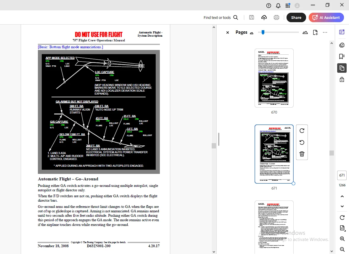
Automatic Flight – Approach Profile 670
Automatic Flight – Go-Around 671
Automatic Flight – Windshear Recovery 673
Automatic Flight Limit Modes 673
30 EICAS Messages 675
Automatic Flight EICAS Messages 675
5-Communications 677
Table Of Contents 677
10 Controls and Indicators 679
Audio Control Panel 679
Pilot Call Panel 680
Radio System 681
VHF Communication Panel 681
HF Communication Panel 682
Miscellaneous Communication Controls 683
Control Wheel Microphone/Interphone Switch 683
Service Interphone Switch 683
Flight Deck Speaker 684
Captain/First Officer/First Observer Jack Panels 684
ACARS or SATCOM Control 685
ACARS Access Through Control Display Units (CDU) 685
Cockpit Voice Recorder Panel 686
Emergency Locator Transmitter 687
20 System Description 689
Introduction 689
Audio Control Panels 689
Radio Communication Systems 690
HF Communication System 690
VHF Communication System 690
Selective Calling (SELCAL) System 691
Aircraft Communication Addressing and Reporting System (ACARS) 691
Voice Recorder System 691
Fuselage Mounted Emergency Locator Transmitter (ELT) 692
Communication Crew Alerting System 692
Crew Communications Messages 692
Communication Alert Categories 692
Selective Calling (SELCAL) Messages 693
30 Interphone Systems 695
Interphone Communication System 695
Flight Interphone System 695
Cabin Interphone System 696
Service Interphone System 696
Passenger Address System 696
40 Data Link System 699
Aircraft Communication Addressing and Reporting System (ACARS) 699
ACARS Control 699
ACARS Control Through Control Display Units (CDU) 699
ACARS Data Mode 700
ACARS Message Display 700
ACARS Voice Mode 700
Online ACARS Voice Mode 701
ACARS Air-to-Ground Voice Calls (Typical) 701
ACARS Ground-to-Air Voice Calls (Typical) 701
Manual ACARS Override 701
Data Link Related EICAS Messages 701
50 EICAS Messages 703
EICAS Communications Alert Messages 703
Crew Communication 703
Selective Calling (SELCAL) 703
6-Electrical 705
Table Of Contents 705
10 Controls and Indicators 707
Electrical Panel 707
Battery/Standby Control Panel 709
Hydraulic Generator Test Switch 710
20 System Description 713
Introduction 713
AC Electrical System 713
AC Electrical System Power Sources 713
AC Electrical Power Distribution 714
AC Electrical System Schematic (Hydraulic Driven Generator) 717
DC Electrical System 718
DC Electrical System Schematic 719
Battery/Standby Power System 720
Hot Battery Bus 720
Battery Bus 720
Standby DC Bus 720
Standby AC Bus 721
Battery/Standby System Schematic 722
Hydraulic Driven Generator 723
Battery/Standby System Schematic (Hydraulic Driven Generator Operating) 724
30 EICAS Messages 725
Electrical EICAS Messages 725
7-Engines, APU 727
Table Of Contents 727
10 Controls and Indicators (RR) 731
EICAS Displays 731
Primary Engine Indications 731
Secondary Engine Indications 738
Compact Engine Indications 746
Engine Controls 747
Thrust Levers 747
Fuel Control Switches 748
Electronic Engine Control (EEC) 749
Engine Limiter Control (ELC) 749
Engine Control Panel 750
Thrust Mode Select Panel (TMSP) 751
EICAS Control Panel 752
11 Controls and Indicators (PW) 755
EICAS Displays 755
Primary Engine Indications 755
Secondary Engine Indications 762
Compact Engine Indications 769
Engine Controls 770
Thrust Levers 770
Fuel Control Switches 771
Engine Control Panel 772
Thrust Mode Select Panel (TMSP) 773
EICAS Control Panel 774
15 Controls and Indicators 777
Auxiliary Power Unit (APU) 777
APU Controls 777
APU Indications 778
20 Engine System Description (RR) 779
Introduction 779
Engine Indications 779
Primary Engine Indications 779
Secondary Engine Indications 779
Normal Display Format 780
Compact Display Format 780
Engine Secondary Data Cue 781
Engine Pressure Ratio (EPR) 781
Thrust Management Computer (TMC) 782
Reduced Takeoff Thrust 783
Assumed Temperature Takeoff 783
Reduced Climb Thrust 784
Electronic Engine Control (EEC) 784
Engine Limiter Control (ELC) 785
Overboost/Overspeed Protection 785
Idle Selection 785
Engine Start and Ignition System 786
Engine Start 786
Starter Operation 786
In-Flight Start 787
Engine Ignition 787
Engine Start and Ignition System Schematic 788
Engine Fuel System 789
Fuel control Unit 789
Engine and Spar Valves 789
Fuel Filters 789
Fuel Flow Measurement 790
Engine Fuel System Schematic 791
Engine Oil System 792
Engine Oil System Schematic 793
Thrust Reverser System 794
Thrust Reverser Schematic 795
Airborne Vibration Monitoring System 796
21 Engine System Description (PW) 797
Introduction 797
Engine Indications 797
Primary Engine Indications 797
Secondary Engine Indications 797
Normal Display Format 798
Compact Display Format 798
Engine Secondary Data Cue 799
Engine Pressure Ratio (EPR) 799
Thrust Management Computer (TMC) 800
Reduced Takeoff Thrust 801
Assumed Temperature Takeoff 801
Reduced Climb Thrust 802
Electronic Engine Control (EEC) 802
EPR and N1 Control Modes 802
N2 Control Mode 803
Engine Stator Vanes 803
Overspeed Protection 803
Idle Selection 804
Engine Start and Ignition System 804
Engine Start 805
Starter Operation 805
In-Flight Start 806
Engine Ignition 806
Engine Start and Ignition System Schematic 807
Engine Fuel System 808
Fuel control Unit 808
Engine and Spar Valves 808
Fuel Filter 808
Fuel Flow Measurement 809
Engine Fuel System Schematic 809
Engine Oil System 810
Engine Oil System Schematic 811
Thrust Reverser System 812
Thrust Reverser Schematic 813
Airborne Vibration Monitoring System 814
30 APU System Description 815
Introduction 815
APU Operation 815
APU Start 815
APU Run 816
APU Shutdown 816
Protection System 816
40 EICAS Messages (RR) 817
Engines, APU EICAS Messages 817
41 EICAS Messages (PW) 819
Engines, APU EICAS Messages 819
8-Fire Protection 821
Table Of Contents 821
10 Controls and Indicators 823
Engine Fire Protection 823
Engine Fire Panel 823
Fuel Control Switches 824
Fire Warning Light 824
Cargo and APU Fire Protection 825
Cargo and APU Fire Panel 825
Wheel Well Fire Light 826
APU Ground Control Fire Protection Panel 827
Fire/Overheat Test Panel 828
20 System Description 831
Introduction 831
Engine Fire Protection 831
Engine Fire and Overheat Detection 831
Engine Fire Warning 831
Engine Overheat Caution 832
Engine Fire Extinguishing 832
Engine/APU Fire and Override Switches 832
APU Fire Protection 832
APU Fire Detection 833
APU Fire Warning 833
APU Fire Extinguishing 833
Main Gear Wheel Well Fire Protection 834
Main Gear Wheel Well Fire Detection 834
Main Gear Wheel Well Fire Warning 834
Cargo Compartment Fire Protection 834
Cargo Compartment Smoke Detection 834
Cargo Compartment Fire Warning 834
Cargo Compartment Fire Extinguishing 835
Lavatory Fire Protection 835
Lavatory Fire Detection and Annunciation 835
Lavatory Fire Extinguishing 835
Fire and Overheat Detection System Fault Test 836
30 System EICAS Messages 837
Fire Protection EICAS Messages 837
9-Flight Controls 839
Table Of Contents 839
10 Controls and Indicators 841
Pitch and Stabilizer Trim Systems 841
Control Wheel and Column 841
Stabilizer Trim System 842
Stabilizer Trim Lights 843
Aileron and Rudder Trim Controls 843
Aileron Trim Indicator 843
Aileron and Rudder Trim 844
Rudder System 844
Rudder/Brake Pedals 844
EICAS Status Display 845
Yaw Damper Switches 845
Rudder System Light 846
Flight Control Shutoff Switches 846
Speedbrakes 847
Speedbrake Lever 847
Speedbrake Lights 847
Flap System 848
Flap Controls 848
Flap Position Indicator/Alternate Flaps Selector 850
20 System Description 853
Introduction 853
Pilot Controls 853
Flight Control Surfaces 854
Flight Control Surface Locations 854
Pitch Control 854
Elevator 854
Actuator Control Hydraulic Power Distribution 856
Stabilizer Trim Control 857
Electric Trim 857
Alternate Trim 857
Automatic Trim 857
Non-normal Operation 857
Roll Control 858
Ailerons 858
Yaw Control 859
Rudder 859
Rudder Ratio 859
Yaw Damping 859
Spoilers 859
Spoiler Speedbrake Operation 860
Flaps and Slats 860
Flap and Slat Sequencing 861
Flap Load Relief 861
Autoslats 861
Flap/Slat Non-Normal Operation 862
Alternate Flap Operation 862
Leading Edge Disagreement 862
Leading Edge Asymmetry 862
Trailing Edge Disagreement 862
Trailing Edge Asymmetry 863
Load Relief Inoperative 863
Hydraulic Driven Generator 863
30 EICAS Messages 865
Flight Controls EICAS Messages 865
10-Flight Instruments, Displays 867
Table Of Contents 867
10 EFIS Controls and Indicators 871
Attitude Director Indicator (ADI) Display 871
ADIs with Flight Mode Annunciations (FMA) on Bottom 871
ADIs with Flight Mode Annunciations (FMA) on Top 875
ADI Speed Tape 880
ADI Failure Flags and Annunciations 884
Horizontal Situation Indicator (HSI) Display Modes 886
MAP Mode 886
CTR MAP Mode 890
APP Mode 894
CTR APP Mode 896
VOR Mode 898
CTR VOR Mode 900
PLAN Mode 902
HSI Symbology 905
Heading, Track, and Wind 905
Radio Navigation 907
Map 910
Radar 914
TCAS 917
Look-Ahead Terrain 919
Predictive Windshear 920
HSI Failure Flags and Annunciations 921
Instrument Switching 922
Left Instrument Source Selector Panel (Upper) 922
Left Instrument Source Selector Panel (Lower) 923
Right Instrument Source Selector Panel (Upper) 924
Right Instrument Source Selector Panel (Lower) 925
EFI/IRS Interface Diagram 927
Heading Reference Switch 928
EFIS Control Panel 929
20 EFIS System Description 933
Introduction 933
EFIS Symbol Generators 933
EFIS Control Panels 933
Attitude Director Indicator 933
Attitude Display 934
Mode Annunciations 934
Flight Director Commands 934
Glide Slope and Localizer Deviation Displays 934
Attitude Comparator 934
Height Alert 934
Radio Altitude and Decision Height 935
Pitch Limit Indicator 935
Ground Speed Display 935
Airspeed Display 935
Horizontal Situation Indicator (HSI) 936
Display Orientation 936
Track 936
MAP Mode 936
VOR Mode 936
APP Mode 936
PLAN Mode 937
Weather Radar Display 937
Traffic 937
Terrain Display 937
Predictive Windshear 937
EFIS Failures Flags and Annunciations 937
Light Sensing and Brightness Control 938
30 Conventional Instruments Controls and Indicators 939
Conventional Flight Instruments 939
Mach/Airspeed Indicator (Electric) 939
Primary Altimeter (Electric) 940
Radio Distance Magnetic Indicator 941
Vertical Speed Indicator 943
Clock 943
Standby Flight Instruments 945
Standby Attitude Director Indicator (Standby ADI) 945
Standby Airspeed Indicator (Pneumatic) 947
Standby Altimeter (Pneumatic) 947
Standby Magnetic Compass 948
Flight Recorder 948
40 Conventional Instruments System Description 949
Introduction 949
Primary Flight Instruments 949
Mach/Airspeed Indicator 949
Primary Altimeter 949
Radio Distance Magnetic Indicator (RDMI) 949
Vertical Speed Indicator 950
Clock 950
Standby Flight Instruments 950
Standby Attitude Director Indicator (Standby ADI) 950
Standby Airspeed Indicator (Pneumatic) 950
Standby Altimeter (Pneumatic) 950
Standby Magnetic Compass 950
Flight Recorder 951
Air Data System 951
Pitot-Static System Schematic (ADCs) 952
Total Air Temperature (TAT) 952
True Airspeed/Static Air Temperature (TAS/SAT) 953
50 EICAS Messages 955
Flight Instruments, Displays EICAS Messages 955
11-Flight Management, Navigation 957
Table Of Contents 957
10 Controls and Indicators 963
Flight Management System 963
Control Display Unit (CDU) 963
Function and Execute Keys 964
Alpha/Numeric and Miscellaneous Keys 966
CDU Page Components 967
FMC Annunciator Light 968
Inertial System 969
Inertial Reference System 969
Radio Navigation Systems 972
Automatic Direction Finding (ADF) Control 972
Transponder Panel 973
ILS Control Panel 974
VOR Control Panel 975
Marker Beacon Lights 976
Weather Radar 977
Weather Radar Panel 977
Weather Radar Switch 979
20 Navigation Systems Description 981
Introduction 981
Navigation Systems Flight Instrument Displays 981
Inertial Reference System 981
Inertial Reference System Operation 981
IRS Alignment 981
IRS Attitude 983
IRS Power 983
Radio Navigation Systems 983
Automatic Direction Finding (ADF) 983
Distance Measuring Equipment (DME) 983
VOR 984
Marker Beacon 985
Multi-Mode Receiver 985
Instrument Landing System (ILS) 985
Global Positioning System (GPS) 985
GPS Displays 985
GPS Data 985
GPS System Schematic 986
Transponder 987
Weather Radar 987
30 Flight Management System Description 989
Introduction 989
Flight Management Computer (FMC) 989
Control Display Units (CDUs) 990
31 Flight Management System Operation 991
Introduction 991
Preflight 991
Takeoff 992
Climb 992
Cruise 992
Descent 992
Approach 992
Flight Complete 992
Operational Notes 992
Terminology 993
Navigation Position 994
FMC Position Update 995
FMC Polar Operations 996
Navigation Performance 997
Lateral Navigation (LNAV) 998
Waypoints 998
Engine Out SID1004
HSI Map Displays1005
Vertical Navigation (VNAV)1005
Speed/Altitude Constraints1005
Takeoff and Climb1007
Cruise1009
Mode Control Panel Speed Intervention1010
Descent1010
Approach1015
Missed Approach1016
Cruise and Descent Profile (Nonprecision Approach)1017
VNAV Engine Out Operation1019
Data Entry Rules1021
Altitude Entry1021
Airspeed Entry1022
Data Pairs1022
32 Flight Management Computer1023
FMC Databases1023
Thrust Management1023
Fuel Monitoring1024
Loss of FMC Electrical Power1025
FMC Failure1025
Single FMC Failure1025
Dual FMC Failure1025
FMC Resets1026
40 FMC Preflight1027
Introduction1027
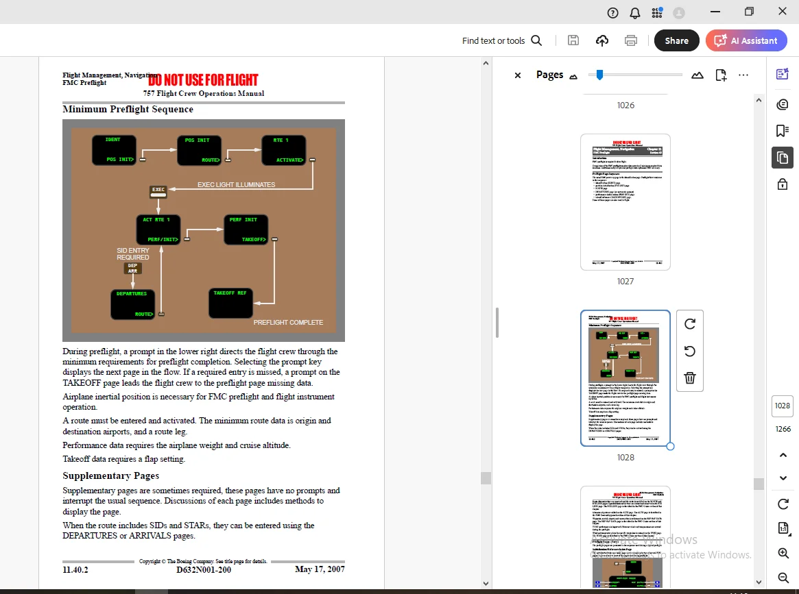
Preflight Page Sequence1027
Minimum Preflight Sequence1028
Supplementary Pages1028
Preflight Pages – Part 11029
Initialization/Reference Index Page1029
Identification Page1031
Position Initialization Page1033
Position Reference Pages1036
Route Page1042
Preflight Pages – Part 21048
Departure/Arrival Index Page1048
Departures Page1049
Navigation Radio Page1052
Performance Initialization Page1053
Takeoff Reference Page1055
Menu Page1058
41 FMC Takeoff and Climb1061
Introduction1061
Takeoff Phase1061
Climb Phase1061
Climb Page1062
Engine Out Climb1065
Route Legs Page1066
Engine Out Departure 1070
Air Turn-Back1070
Arrivals Page1070
42 FMC Cruise1073
Introduction1073
LNAV Modifications1073
RTE LEGS Page Modifications1073
Add Waypoints1074
Delete Waypoints1075
Change Waypoint Sequence1076
Remove Discontinuities1077
Direct To And Intercept Course To1079
Intercept Course From1080
SELECT DESIRED Waypoint (WPT) Page1083
Airway Intercept1085
Route Offset1087
Cruise Page1088
All Engine Cruise1088
Engine Out Cruise1091
VNAV Modifications1093
Cruise Climb1093
Planned Step Climb1094
Calculated Step Climb1094
Cruise Descent 1097
Early Descent1097
Navigation Data1098
Reference Navigation Data Page1098
Fix Information Page1101
In-Flight Position Update1103
Route and Waypoint Data1104
Route Data Page1104
Wind Data1105
Wind Page1106
Progress Pages1108
Progress Page 11108
Progress Page 21111
Position Report Page1113
43 FMC Descent and Approach1117
Introduction1117
Early Descent1117
Descent1117
Descent Page1117
Descent Forecast Page1120
Offpath Descent Page1122
Engine Out Descent1124
Approach1124
Arrivals Page – IFR Approaches1124
Vertical Angle Display on the Route Legs Page1126
Arrivals Page – VFR Approaches1127
Approach Reference Page1129
Alternate Airport Diversions1131
Alternate Page1131
XXXX Alternate Page1134
Holding1137
Hold Page (First Hold)1138
Hold Page (Existing Hold)1141
50 FMS Alternate Navigation System Description1143
Introduction1143
Alternate Navigation Waypoints1143
Alternate Lateral Navigation1143
Route Changes1144
Course Reference1144
Alternate Navigation CDU Pages1144
Alternate Navigation Legs Page1145
Alternate Navigation Progress Page1146
60 EICAS Messages1149
EICAS and CDU Messages1149
FMC Messages1150
FMC Alerting Messages 1150
FMC Advisory Messages 1152
CDU Annunciator Lights1153
12-Fuel1155
Table Of Contents1155
10 Controls and Indicators1157
Fuel System1157
Fuel Indications1158
Fuel Quantity Indicator1158
Fuel Quantity Test1159
20 System Description1161
Introduction 1161
Fuel Quantity1161
Fuel Temperature1161
Fuel Pumps1161
Fuel Crossfeed1162
Suction Feed1163
Fuel Configuration Light1163
Fuel Imbalance1163
Fuel Tank Locations and Capacities1164
Fuel Tank Locations1164
Fuel Tank Capacities1164
Fuel System Schematic1165
APU Fuel Feed1165
Fuel System FMS CDU Messages1166
30 EICAS Messages1167
Fuel System EICAS Messages1167
13-Hydraulics1169
Table Of Contents1169
10 Controls and Indicators1171
Hydraulic Panel1171
Status Display1172
Miscellaneous Hydraulic System Controls1173
Power Transfer Unit1173
Ram Air Turbine1173
20 System Description1175
Introduction 1175
Hydraulic Systems Schematic1176
Left Hydraulic System 1177
Fluid Supply1177
Engine-driven Pump1177
Electric Motor-driven Pumps1177
Power Transfer Unit (PTU)1178
System Pressure Indications1178
Right Hydraulic System1178
Fluid Supply1178
Engine-driven Pump1178
Electric Motor-driven Pump1179
System Pressure Indications1179
Reserve Brakes System1179
Center Hydraulic System1179
Fluid Supply1179
Electric Motor-driven Pump1179
System Pressure Indications1179
Ram Air Turbine (RAT) Pump1180
30 EICAS Messages1181
Hydraulics EICAS Messages 1181
14-Landing Gear1183
Table Of Contents1183
10 Controls and Indicators1185
Landing Gear Panel1185
Gear Indications1185
Gear Extension/Retraction1186
Nose Wheel Steering Tiller1187
Brake System1187
Rudder/Brake Pedals1187
Auto Brakes Selector1188
Parking Brake Handle1188
Brake Accumulator Pressure Indicator1189
Brake Source Light1189
Reserve Brakes1189
Antiskid Light1190
Brake Temperature1190
20 System Description1193
Introduction1193
Air/Ground Sensing System1193
Landing Gear Operation1193
Landing Gear Retraction1194
Landing Gear Extension1194
Landing Gear Alternate Extension1194
Nose Wheel Steering1195
Brake System1195
Normal Brake Hydraulic System1195
Alternate Brake Hydraulic System1195
Reserve Brakes1196
Brake Accumulator1196
Antiskid Protection1196
Autobrake System1196
Parking Brake1197
Brake Temperature Indication1198
30 EICAS Messages1199
Landing Gear EICAS Messages 1199
15-Warning Systems1201
Table Of Contents1201
10 Controls and Indicators1205
Engine Indication and Crew Alerting System (EICAS)1205
Primary EICAS Display1205
Secondary EICAS Display1207
EICAS Messages1209
EICAS Status Display1212
EICAS Control Panel1213
Caution Cancel/Recall Switches1213
Warning System Switches and Lights1214
Master Warning/Caution Reset Switches and Lights1214
Miscellaneous Lights1215
Ground Proximity Warning System (GPWS) 1216
GPWS Controls1216
GPWS Immediate-Alert Annunciations1217
Enhanced GPWS 1218
Windshear Warning System1222
Windshear Immediate-Alert Annunciations1222
Predictive Windshear (PWS)1223
Traffic Alert and Collision Avoidance System (TCAS)1225
TCAS Controls1225
TCAS Displays1227
TCAS Vertical Guidance1230
Miscellaneous Switches1231
Stall Warning Test Switches1231
EICAS Test Switch1231
20 System Description1233
Introduction 1233
Engine Indication and Crew Alerting System (EICAS)1233
System Alert Messages1233
System Alert Level Definitions1234
Communication Alerts1234
Status Messages1234
Alert Message Displays 1235
Master Warning/Caution Reset Switches and Lights1235
Flight Deck Panel Annunciator Lights1236
Aural Alerts1236
Alert Inhibits1237
Message Consolidation 1238
Engine Start Message Inhibits1238
Takeoff Inhibits1238
Landing Inhibits1239
Engine Shutdown Inhibits1240
Alert Message Inhibits1240
Altitude Alerting Inhibit1240
Master Caution Lights and Beeper Inhibit1241
EICAS Event Record1241
EICAS Failure Indications1241
Warning System1241
Configuration Alerts1242
Airspeed Alerts1243
Altitude Alerts1244
Ground Proximity Warning System (GPWS)1246
Introduction1246
GPWS Alert Prioritization1247
GPWS Immediate-Alert Modes1248
GPWS Callouts1249
Look-Ahead Alerts and Display1250
Windshear Warning System1253
Windshear Immediate-Alerts1253
Predictive Windshear (PWS)1253
Traffic Alert and Collision Avoidance System (TCAS)1257
Normal Operations1257
Resolution Advisories (RA) and Displays1257
Traffic Advisories (TA) and Displays1258
Automatic TA and RA Display1259
Proximate Traffic and Other Traffic Displays1259
TCAS Voice Annunciations1260
Inhibits1262
Non-Normal Operations1262
30 EICAS Messages1265
Warning Systems EICAS Messages1265
GPWS1265
TCAS1265
Configuration1265
Miscellaneous1266
DESCRIPTION:
Boeing 757-200 Flight Crew Operations Manual – PDF DOWNLOAD
General:
- The airplanes listed in the table below are covered in the Flight Crew Operations Manual (FCOM). The numbers are used to distinguish data peculiar to one or more, but not all of the airplanes. Where data applies to all airplanes listed, no reference is made to individual airplane numbers.
- Use of the table below permits flight crew correlation of configuration differences by number within an operator’s fleet for airplanes covered in this manual.
- Configuration data reflects the airplane as delivered configuration and is updated for service bulletin incorporations in conformance with the policy stated in the introduction section of this chapter.
- Registry number is supplied by the national regulatory agency. Serial and tabulation numbers are supplied by Boeing.
- This Flight Crew Operations Manual has been prepared by The Boeing Company.
- The purpose of this manual is to: provide the operating limitations, procedures, performance, and systems information the flight crew needs to safely and efficiently operate the 757 airplane during all anticipated operations serve as a comprehensive reference for use during transition training for the 757 airplane serve as a review guide for use in recurrent training and proficiency checks
- • provide necessary operational data from the FAA approved airplane flight manual (AFM) to ensure that legal requirements are satisfied
- establish standardized procedures and practices to enhance Boeing operational philosophy and policy. This manual is prepared for the owner/operator named on the title page specifically for the airplanes listed in the “Model Identification” section. It contains operational procedures and information, which apply only to these airplanes.
- The manual covers the Boeing delivered configuration of these airplanes. Changes to the delivered configuration are incorporated when covered by contractual revision agreements between the owner/operator and The Boeing Company. This manual is not suitable for use for any airplanes not listed in the “Model Identification” section. Further, it may not be suitable for airplanes that have been transferred to other owners/operators.
- Owners/operators are solely responsible for ensuring the operational documentation they are using is complete and matches the current configuration of the listed airplanes. This includes the accuracy and validity of all information furnished by the owner/operator or any other party.
- Owners/operators receiving active revision service are responsible to ensure that any modifications to the listed airplanes are properly reflected in the operational procedures and information contained in this manual. The manual is periodically revised to incorporate pertinent procedural and systems information.
- Items of a more critical nature will be incorporated in operational bulletins and distributed in a timely manner. In all cases, such revisions and changes must remain compatible with the approved AFM with which the operator must comply. In the event of conflict with the AFM, the AFM shall supersede.
G.B 04/04/25