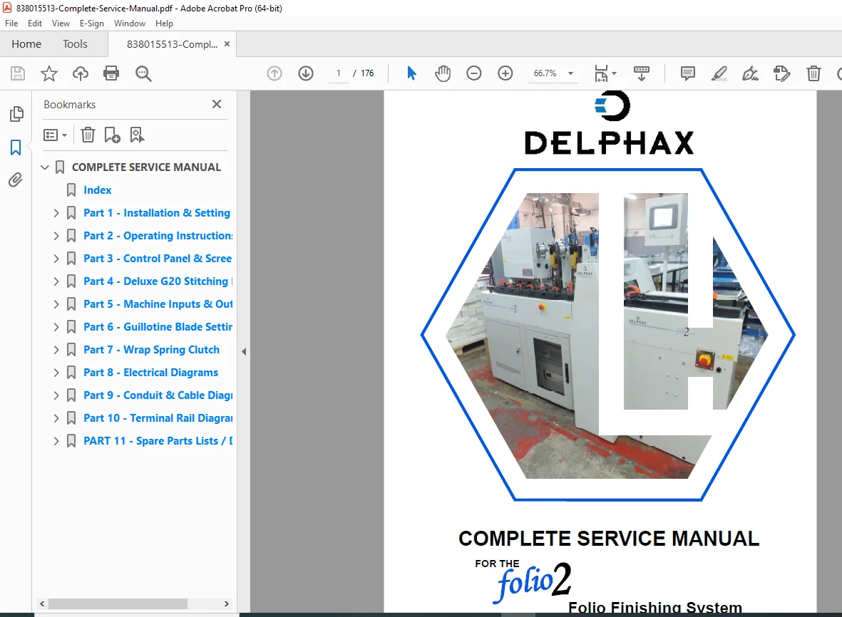
Boldt Folio2 Finishing System Service Manual PDF
Original price was: $95.00.$32.95Current price is: $32.95.
Complete factory service manual for Boldt SA Folio2 folio finishing system used in commercial bookbinding operations. Includes installation procedures, operating instructions, HMI control panel programming, Deluxe G20 stitching head service, electrical diagrams, PLC inputs/outputs, guillotine blade settings, and comprehensive spare parts lists. Essential technical documentation for print finishing technicians and bindery equipment service professionals. Instant PDF download.
Description
Boldt Folio2 Finishing System Service Manual Bookbinding Repair Guide PDF DOWNLOAD
Description
Boldt SA Folio2 Folio Finishing System Complete Service Manual – Professional Technical Documentation
This comprehensive Boldt Folio2 service manual PDF provides complete installation, operation, programming, maintenance, and troubleshooting information for the Boldt SA Folio2 folio finishing system. This professional-grade bookbinding equipment repair guide is essential for print finishing technicians, bindery service engineers, and commercial printing facility maintenance personnel working with automated book production equipment.
File Details
- Manual Name: Complete Service Manual – Folio2 Folio Finishing System
- Equipment Covered: Boldt SA Folio2 Folio Finishing System
- Manufacturer: Boldt SA (Delphax)
- Author: Charlie Lawrence
- Total Pages: 176 pages
- PDF Quality: High-quality optimized factory original
- Language: English
- Publication Date: November 2012 (Updated January 2013)
- Document Format: A4 size
Complete Manual Structure and Content
Part 1: Installation & Setting To Work
- Installation Sequence
- Site preparation requirements
- Unpacking and inspection procedures
- Component positioning guidelines
- Safety considerations during installation
- Setting to Work Procedures
- Initial power-up sequence
- System commissioning steps
- Calibration procedures
- Test run protocols
- Floor Plan and Side Elevation
- Dimensional drawings
- Space requirements
- Access clearances
- Utility connection locations
- Technical Data
- Machine specifications
- Power requirements (240V AC, 3-phase)
- Air pressure requirements
- Operating environment parameters
- Production capacity ratings
Part 2: Operating Instructions
- General Description
- System overview and architecture
- Module identification (Infeed, Main Track, Stitching, Guillotine, Binding)
- Material flow through the system
- Production process explanation
- Operator Controls
- Control panel layout and functions
- Manual Operating Buttons:
- Stitch 1 and Stitch 2 controls
- Feed Tape function
- Binding Unit cycle control
- Emergency stop procedures
- Safety interlocks
- PLC Module Rack Controls:
- Motor overload module indicators
- Emergency stop relay system
- Fuse locations and ratings
- Heater controls
- Start Up & Normal Operating
- Pre-start checklist
- System startup sequence
- Folio infeed procedures
- Book count and folio count monitoring
- Normal production operation
- Shutdown procedures
- Operating Adjustments
- Tape feed length calibration (pages to tape length conversion)
- Tape positioning adjustments
- Binding pressure and timing settings
- Stitching head adjustments
- Speed and timing parameters
- Fault Correction
- Common operational faults
- Fault diagnosis procedures
- Corrective actions
- Error message interpretation
- Appendix 1: HMI Screens (reference to Part 3)
- Appendix 2: Deluxe G20 (reference to Part 4)
Part 3: HMI Control Panel & Screens
- Human-Machine Interface Overview
- Touchscreen navigation
- Screen hierarchy and flow
- Job Setup Mode Screens
- SELECT NO. OF PAGES configuration
- Page count to tape length correlation
- Typical settings reference (25 page = 300, 50 page = 400, 100 page = 500)
- Automatic Control Screen
- Production monitoring displays
- Real-time status indicators
- Fault message display (e.g., “MOTOR(S) OVERLOAD”)
- Book count and folio count displays
- Parameter Entry Screens
- Numerical input procedures
- Setting modification protocols
- Data validation
- Diagnostic and Service Screens
- System status monitoring
- Input/output verification
- Troubleshooting displays
Part 4: Deluxe G20 Stitching Head
- G20 Stitching Unit Overview
- Head design and operation
- Wire feeding mechanism
- Stitching cycle sequence
- Component Identification
- Wire spool and feed system
- Forming mechanism
- Clincher plate assembly
- Drive motor and clutch
- Service Procedures
- Wire loading and threading
- Head removal and installation
- Adjustment procedures
- Timing and synchronization
- Troubleshooting
- Loose stitch prevention
- Wire jam clearing
- Clincher plate maintenance
- Common stitching faults
- Parts Breakdown
- Exploded view diagrams
- Component part numbers
- Replacement procedures
Part 5: Machine Inputs & Outputs
- PLC Input Devices
- Microswitches locations and functions
- Photocell sensors
- Reed switches
- Position sensors
- Safety interlock inputs
- PLC Output Devices
- Clutch controls
- Solenoid valves
- Indicator lamps
- Motor controls
- Heater outputs
- 24V DC Power Distribution
- Input power supply module (2.5A)
- Output power supply module (5A)
- Power routing and protection
- Input/Output Mapping
- I/O address assignments
- Signal descriptions
- Wiring terminal references
Part 6: Guillotine Blade Setting
- Blade Installation Procedures
- Blade removal safety protocols
- New blade installation
- Blade alignment techniques
- Blade Adjustment
- Cutting height settings
- Blade angle optimization
- Clearance adjustments
- Blade Maintenance
- Sharpening requirements
- Replacement intervals
- Blade inspection criteria
- Safety Precautions
- Lockout/tagout procedures
- Top cover interlock system
- Blade handling safety
Part 7: Wrap Spring Clutch Service Data
- Clutch Operating Principles
- Wrap spring clutch technology
- Engagement and disengagement mechanics
- Torque transmission
- Clutch Locations and Applications
- Binding unit clutch (pressure bar control)
- Stitching head clutches
- Other clutch applications
- Service Procedures
- Clutch inspection
- Adjustment procedures
- Replacement techniques
- Timing verification
- Clutch Timing Data
- Top Dead Centre (TDC) positions
- Bottom Dead Centre (BDC) positions
- Variable time delay settings (tape adhesion dwell time)
- Cycle timing specifications
Part 8: Electrical Diagrams
- Complete System Schematics
- Power distribution diagrams
- Motor control circuits
- Control logic schematics
- Safety circuit diagrams
- Single Phase Motor Circuits
- Infeed track motor
- Main track motor
- Stitcher 1 motor
- Stitcher 2 motor
- Tape binding unit motor
- Three Phase Motor Circuits
- Hydraulic motor starter circuit
- Overload protection
- Control Circuits
- Emergency stop relay system (Schneider-Electric safety relay)
- PLC power and I/O circuits
- Heater control circuits
- Lighting circuits
- Module Rack Wiring
- 19″ rack configuration (12U height)
- Seven module layout and interconnections
- Edge connector pinouts
Part 9: Conduit Wiring Diagrams
- Physical Wiring Routes
- Conduit routing throughout machine
- Wire identification and color codes
- Junction box locations
- Installation Wiring
- Field wiring connections
- Power supply routing
- Signal cable routing
- Cable Specifications
- Wire gauge requirements
- Cable types and ratings
- Connector types
Part 10: Terminal Rail Wiring Diagrams
- Terminal Block Layouts
- Rear rack terminal assignments
- Terminal numbering system
- Signal routing to modules
- Hard Wiring Connections
- Machine assembly connections
- Sensor and switch wiring
- Actuator and motor connections
- Wiring Reference Tables
- Terminal-to-device mapping
- Wire color coordination
- Troubleshooting wire traces
Part 11: Spare Parts Lists & Drawings
- Comprehensive Parts Catalogs
- Module-by-module parts breakdown
- Part numbers and descriptions
- Quantity per machine
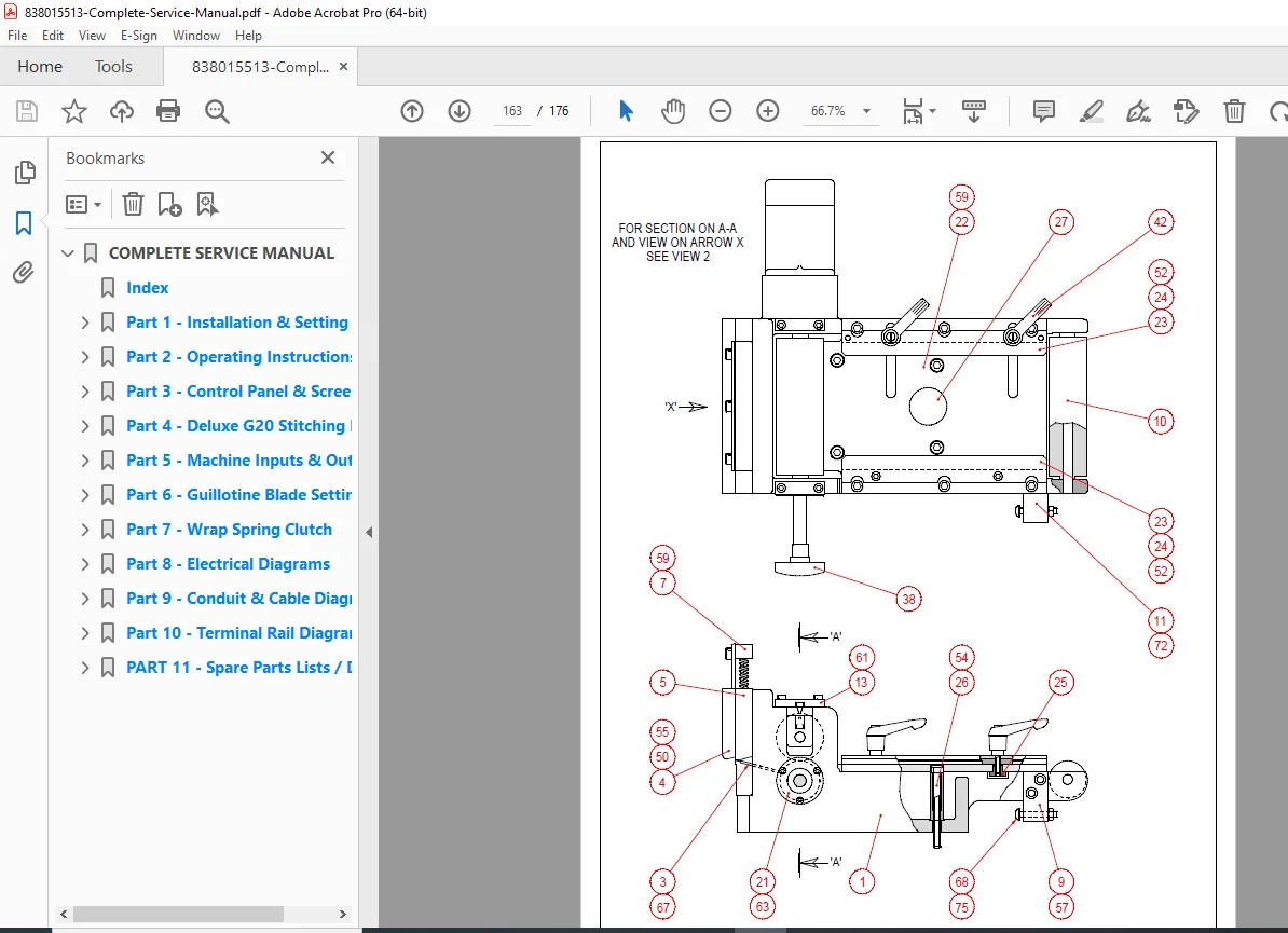
- Exploded View Drawings
- Detailed mechanical assemblies
- Component relationships
- Assembly sequence references
- Consumables and Wear Items
- Recommended stock items
- Replacement intervals
- Ordering information
- Critical Spare Parts
- Emergency stock recommendations
- Long lead-time items
- System-specific components
Key Technical Features
System Modules:
- Infeed Track Module – Initial folio acceptance and positioning
- Main Track Module – Material transport and sequencing
- Guillotine Module – Precision folio trimming
- Stitching Units – Dual Deluxe G20 stitching heads
- Binding Unit – Tape application and adhesion system
Control System:
- PLC-Based Control – Programmable logic controller for automation
- HMI Touchscreen – User-friendly operator interface
- Safety Relay System – EU-compliant Schneider-Electric safety components
- Module Rack Design – Standard 19″ rack with plug-in modules
Safety Systems:
- Emergency stop circuits (dual channel)
- Guillotine top cover interlock
- RED BAR fault protection
- Motor thermal and magnetic overload protection
- Safe shutdown protocols for all 240V AC and 24V DC devices
Who Needs This Manual?
- Print Finishing Technicians – Daily maintenance and troubleshooting reference
- Bindery Equipment Service Engineers – Complete technical documentation for repairs
- Commercial Printing Facilities – In-house maintenance capability reduces downtime
- Print Production Managers – Understanding system operation and capabilities
- Equipment Installation Teams – Installation and commissioning procedures
- Technical Training Programs – Educational resource for bindery equipment training
Equipment Specifications Covered
Production Capabilities:
- Automated folio finishing and bookbinding
- Adjustable page count configurations (25 to 100+ pages)
- Continuous production monitoring
- Preset book count capability
Electrical Requirements:
- 240V AC power supply
- Three-phase for hydraulic motor
- Single-phase motors (5 units)
- 24V DC control circuits
Major Components:
- Deluxe G20 dual stitching heads
- Guillotine cutting system
- Tape binding system with variable dwell time
- PLC module rack (7 modules)
- HMI control panel
Why Choose This Digital Download?
This Boldt Folio2 service manual PDF is the complete factory service documentation used by authorized Boldt SA service engineers. Commercial print finishing equipment downtime is extremely costly – this manual empowers you to diagnose and repair issues quickly without waiting for expensive factory technicians.
Instant download provides immediate access to 176 pages of detailed technical information, electrical schematics, parts diagrams, and troubleshooting procedures. Keep this essential reference on your tablet or laptop for quick access on the production floor. With comprehensive PLC I/O documentation and complete wiring diagrams, you’ll minimize downtime and keep your bindery operation running at peak efficiency!
Pricing Rationale:
- Specialized commercial printing/bindery equipment
- 176 pages of comprehensive technical content
- Factory service manual with complete electrical diagrams
- Target audience: professional technicians and service engineers
- Replaces expensive factory documentation (typically $200-400)
- More specialized than general vending equipment
- PLC programming and advanced electrical content adds value
- Competitive with similar industrial bindery equipment manuals