Bomag BC 673-733 RB-5, MTU OM 471 LA Stage V Function.651 Wiring Diagram Manual EN_DE PDF
$26.95
Bomag BC 673-733 RB-5, MTU OM 471 LA Stage V Function.651 Wiring Diagram Manual EN_DE – PDF DOWNLOAD
Description
Bomag BC 673-733 RB-5, MTU OM 471 LA Stage V Function.651 Wiring Diagram Manual EN_DE – PDF DOWNLOAD
FILE DETAILS:
Bomag BC 673-733 RB-5, MTU OM 471 LA Stage V Function.651 Wiring Diagram Manual EN_DE – PDF DOWNLOAD
Language : English
Pages : 140
Downloadable : Yes
File Type : PDF
IMAGES PREVIEW OF THE MANUAL:
TABLE OF CONTENTS:
Bomag BC 673-733 RB-5, MTU OM 471 LA Stage V Function.651 Wiring Diagram Manual EN_DE – PDF DOWNLOAD
Page tree 1
&AAA Title page / cover sheet 1
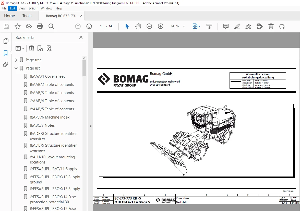
1 Cover sheet 1
&AAB Table of contents 2
2 Table of contents 2
3 Table of contents 3
4 Table of contents 4
5 Table of contents 5
&APD Machine index 6
6 Machine index 6
&ABC Notes 7
7 Notes 7
&ADB Structure identifier overview 8
8 Structure identifier overview 8
9 Structure identifier overview 9
&ALU Layout mounting locations 10
10 Layout mounting locations 10
&EFS Circuit diagram 11
=SUPL Supply 11
11 Supply 11
12 Supply ground 12
13 Supply 13
14 Fuse protection potential 30 14
15 Fuse protection potential 30 15
16 Fuse protection potential 30 16
17 Fuse protection potential 15 17
18 Fuse protection potential 15 18
19 Fuse protection potential 15 19
20 Ignition switch, Pre-excitation, Starting unit 20
21 Power supply driving controller 21
22 Power supply control lever 22
23 Power supply display 23
24 Power supply sensors 24
25 Emergency stop 25
26 Disconnecting battery 26
=COM Communication 27
27 Communication CAN, Diagnosis 27
28 Communication CAN 28
29 Communication CAN 29
30 Communication Ethernet 30
31 Communication USB 31
=ENGI Engine 32
32 Engine – Reversible fan, Pre-heating, Compressor 32
=ENGI1 Engine MTU Stage 5 33
33 Engine – MTU Common Powertrain Controler CPC4 33
34 Engine – MTU Motor Control Module MCM2 34
=EAT1 Exhaust aftertreatment MTU Stage 5 / Tier 4f 35
35 Engine – MTU Aftertreatment Control Module ACM 35
36 Engine – MTU Aftertreatment Control Module ACM 36
37 Engine – MTU Aftertreatment Control Module ACM 37
=MON Monitoring, Failure indicators 38
38 Monitoring, Failure indicators 38
39 Monitoring, Failure indicators 39
40 Monitoring, Failure indicators 40
=DRIV Drive functions 41
41 Accelerator pedal, Slope sensor, Backup alarm 41
42 Speed sensors 42
43 Brake 43
44 Speed ranges 44
45 Driving pump front left 45
46 Driving pump front right 46
47 Driving pump rear left 47
48 Driving pump rear right 48
=STER Steering functions 49
49 Steering functions 49
=WORK Working functions 50
50 Blade and Shovel functions 50
51 Sensors hydraulic cylinders 51
=COMF Comfort functions 52
52 Engine hood 52
53 Central lubrication system 53
54 Sockets 54
55 Warning horns 55
56 Drivers seat 56
57 Cabin – Supply 57
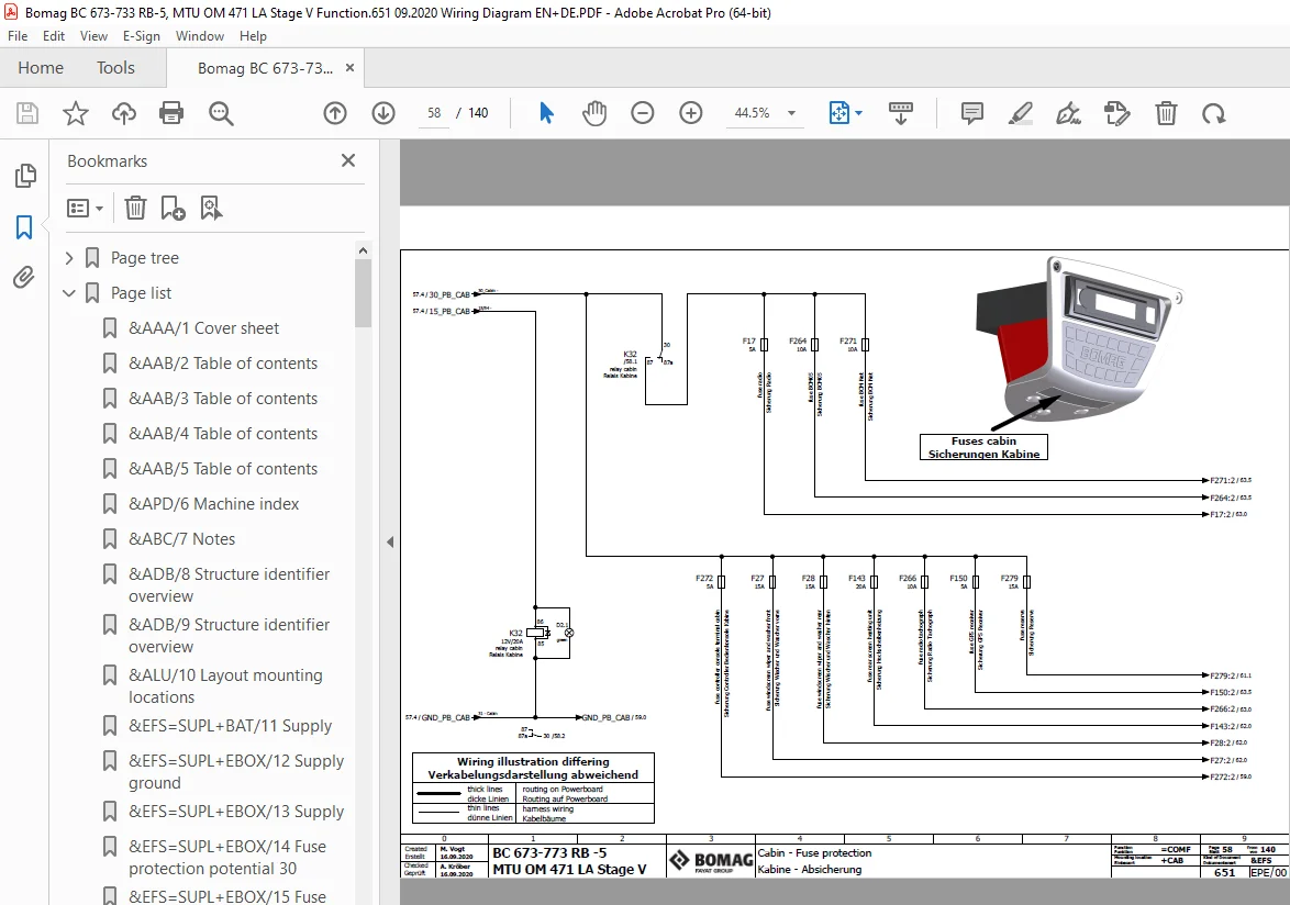
58 Cabin – Fuse protection 58
59 Cabin – Lighting 59
60 Cabin – Lighting 60
61 Cabin – Cabin equipment 61
62 Cabin – Cabin equipment 62
63 Cabin – Radio 63
64 Cabin – Mirror adjustment 64
65 Cabin – Automatic heating and air conditioning 65
66 Cabin – Fresh air blower 66
67 Back up monitoring 67
68 BOMAG Telematics 68
=OPT Optional functions 69
69 Interface measurement 69
70 Cabin – Additional heater 70
&EPB Device tag list electrical engineering 71
71 Device tag list 71
72 Device tag list 72
73 Device tag list 73
74 Device tag list 74
75 Device tag list 75
76 Device tag list 76
77 Device tag list 77
&EMA1 Terminal strip overview 78
78 Terminal strip overview X1 78
79 Terminal strip overview X2 79
80 Terminal strip overview X3 80
81 Terminal strip overview X4 81
82 Terminal strip overview X5 82
83 Terminal strip overview X6 83
84 Terminal strip overview X7 84
85 Terminal strip overview X8 85
86 Terminal strip overview X9 86
87 Terminal strip overview X10 87
88 Terminal strip overview X11 88
89 Terminal strip overview X12 89
&EMA2 Terminal line-up diagram 90
90 Description connection points terminals 90
91 Terminal line-up diagram X1 91
92 Terminal line-up diagram X2 92
93 Terminal line-up diagram X3 – X12 93
94 Terminal line-up diagram X7 – X11 94
&EMA3 Plug overview 95
95 Plug overview 95
96 Plug overview 96
97 Plug overview 97
98 Plug overview 98
99 Plug overview 99
100 Plug overview 100
101 Plug overview 101
102 Plug overview 102
103 Plug overview 103
104 Plug overview 104
105 Plug overview 105
106 Plug overview 106
107 Plug overview 107
108 Plug overview 108
109 Plug overview 109
110 Plug overview 110
111 Plug overview 111
112 Plug overview 112
113 Plug overview 113
114 Plug overview 114
115 Plug overview 115
116 Plug overview 116
117 Plug overview 117
118 Plug overview 118
119 Plug overview 119
120 Plug overview 120
121 Plug overview 121
122 Plug overview 122
123 Plug overview 123
&EFA1 Pin overview ECU 124
124 Pin overview A34 124
125 Pin overview A34 125
126 Pin overview A34 126
127 Pin overview A34 127
128 Pin overview A34 128
129 Pin overview A81 129
130 Pin overview S259 130
131 Pin overview S441 131
&EFA2 Overview CAN communication 132
132 Overview communication CAN 1 132
133 Overview communication CAN 2 133
134 Overview communication CAN 3 134
135 Overview communication CAN Engine 135
136 Overview communication CAN 4 136
&ETL1 Overview central electric 137
137 Overview central electric 137
138 Overview central electric 138
&ETL2 Overview dashboard 139
139 Overview dashboard sidewise 139
140 Overview dashboard cabin rear wall 140
S.V 08/24